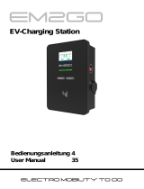
22kW 3-Phasen EM022AC1OCPP wall box charging station

EM2GO 22kW 3-Phasen EM022AC1OCPP wall box charging station User manual

  • Hello! I am an AI chatbot trained to assist you with the EM2GO 22kW 3-Phasen EM022AC1OCPP wall box charging station User manual. I’ve already reviewed the document and can help you find the information you need or explain it in simple terms. Just ask your questions, and providing more details will help me assist you more effectively!
em2go
EV-Ladestation ............1
EV-Charging Station ...9
Bedienungsanleitung
User Manual
ELECTRO MOBILITY TO GO
Cable Type (CT) Socket Type (ST)
22kW | 3-Phasen EM022AC1OCPP
22kW | 3-Phases EM022AS0OCPP
11kW | 3-Phases EM011AC1OCPP
Typ 2 Stecker 3-Phasen Typ 2 Buchse
Danke, dass Sie sich für die EM2GO Ladestation für
Elektrofahrzeuge entschieden haben.
Mit dieser smarten Wallbox haben Sie sich für ein hochpräzises und mit vielen sicherheits-
relevanten Schutzvorrichtungen, sowie Schnittstellen ausgestattetes Ladegerät entschieden,
welches für ein rundum sorgloses Laden Ihres Fahrzeugs und grenzenlose Kommunikation
garantiert.
Wichtiger Hinweis:
Dieses Handbuch enthält wichtige Anweisungen und Informationen, die bei der Installation,
Betrieb und Wartung zu beachten sind. Lesen Sie alle Sicherheitsinformationen und
Warnhinweise in diesem Handbuch, um auf mögliche Gefahren aufmerksam zu werden.
Bewahren Sie dieses Benutzerhandbuch auf.
Warnung
Bei der Verwendung von elektrischen Produkten müssen immer diese grundlegenden
Vorsichtsmaßnahmen beachtet werden.
• Installieren oder verwenden Sie das Ladegerät nicht in der Nähe von explosiven, ätzenden
oder brennbaren Materialien, Chemikalien oder Dämpfen.
• Das Ladegerät darf nur auf nicht brennbaren Untergründen wie Beton, und mindestens
120cm über dem Boden Installiert werden.
• Das Ladegerät muss sicher geerdet sein.
• Schalten Sie die Stromzufuhr des Ladegeräts ab, bevor Sie das Ladegerät montieren
oder warten.
• Das Gerät ist nur für Fahrzeuge konzipiert, die mit der IEC 62196 Norm für Lademodi
kompatibel sind.
• Verwenden Sie das Ladegerät nicht, wenn es defekt ist oder sichtbare Beschädigungen
aufweist.
• Versuchen Sie nicht, das Gerät zu önen, zu zerlegen, zu reparieren, zu manipulieren oder
zu modizieren. Bei Fragen oder Reparaturen wenden Sie sich an unseren Kundendienst.
• Verwenden Sie das Ladegerät nicht, wenn Sie sich im Fahrzeug benden.
• Verwenden Sie das Ladegerät nicht, wenn es starkem Regen, Schnee oder Unwetter
ausgesetzt ist.
• Gehen Sie beim Transport des Ladegeräts stets vorsichtig vor.
• Berühren Sie die Ladeanschlussklemme nicht mit scharfen metallischen Gegenständen
• Ziehen Sie das Ladekabel nicht mit Gewalt oder über scharfe Gegenstände.
Warnhinweise
Das Gerät darf ausschließlich von qualizierten Personen, die mit dem Bau und Betrieb dieser
Art von elektrischen Anlagen vertraut sind, installiert, eingestellt und gewartet werden.
Die Nichtbeachtung dieser Vorsichtsmaßnahme kann zu schweren Verletzungen oder gar
zum Tode führen.
• Eine fehlerhafte Installation und Prüfung des Ladegeräts kann möglicherweise zu Schäden
führen. Für die daraus resultierenden Schäden wird nicht gehaftet.
• Stellen Sie sicher, dass das Ladekabel während des Ladevorgangs richtig positioniert ist,
nicht betreten, beschädigt oder belastet werden kann.
• Überprüfen Sie den Drahtdurchmesser gemäß den örtlichen elektrischen Anforderungen.
• Schalten Sie vor Beginn der Installation die entsprechende Stromversorgung aus.
• Das Ladegerät ist vom Fachpersonal zu Installieren und in Betrieb zu nehmen.
• Vor der Installation muss der Versorgungskabel und Hausanschlusswerte geprüft werden.
Abkürzungen:
A | Ampere, Einheit des Stroms
V | Volt, Einheit der Spannung
EV | Elektrofahrzeug
EVSE | Ausrüstung für die Versorgung von EV nach IEC61851-1
RFID | Radiofrequency Identikationskarte
OCPP | Open Charge Point Protocol, Universelle Kommunikationsschnittstelle mit einem
Zentralen System (Backend)
IP | Schutzklasse
RCMU | Allstromsensitiver Dierenzstromsensor
MCB | Leistungsschutzschalter
Technischen Daten
• Betriebsspannung: 400V AC ±10%, 50-60 Hz, 3-Phasig
• Betriebsstrom: 16A für 11 KW und 32 A bei 22 KW
• Max. Abgabeleistung Typisch 11 oder 22 kW
• Gehäuse: IP54, Spritzwassergeschützt
• Eingangsklemmen: L1, L2, L3, N, PE
Anschluss: Typ 2 Stecker (CT) | Type Steckdose (ST)
• 3 Lademodi
• Kommunikationsschnittstellen: Ethernet 10MBit/s (10BASE-T) (RJ45),
WLAN 802.11b/g/n (2.4GHz), RS-485, PLC, OCPP 1.6-J, ModBus TCP
• Sicherheitseinrichtungen: Notaus-Taste, Überspannungsschutz, Unterspannungsschutz,
Übertemperatur und Überstromschutz, Blitzschutz
Anzeige: Farb-LCD 4,3 Zoll, LED-Dioden
Aufbau: CE Normen IEC 61851-1: 2017 IEC 62196-2:2016, IEC 60364-7-722:2018
Aufbau: Frontplatte Glas, Rückseite Metall
• Verbindungslänge: 7,5 Meter (CT)
• Betriebstemperatur: -30 bis + 55 °C
Abmessungen: 410 x 260 x 140 mm
• Gewicht: 12 Kg
Darstellung der Type2 Stecker / Buchse gemäß IEC 62196-2
1
D
Abb.3Abb.2Abb.1
1
2
Abb.1 Abb.2
Wichtiger Hinweis:
Gemäß §19 NAV vom 21.März 2019 muss der Betrieb von Ladeeinrichtungen für
Elektrofahrzeugen vor Gebrauch (ab 11 KW), sowie vor Installation(ab 22 KW) an den
zuständigen Netzbetreiber gemeldet werden.
Dies kann auch durch den beauftragten Elektroinstallateur erfolgen.
Bitte Informieren Sie sich diesbezüglich bei Ihrem Stromanbieter telefonisch oder Online.
Verpackungsinhalt:
• EV-Ladestation und CEE-Kabel
• 2x RFID-Karten (Oine Betrieb)
• Wandbefestigung inkl. Schrauben und Dübel
• Bedienungsanleitung
Montage
Die EM2GO EV-Ladegeräte bieten eine benutzerfreundliche Bedienoberäche mit den
entsprechenden Kommunikationsschnittstellen.
Warnung
Ein beschädigtes EV-Ladegerät darf auf keinen Fall Montiert werden.
Bitte informieren Sie im Fall einer Beschädigung umgehend Ihren Händler.
Die Installation und Verkabelung muss von einem Fachbetrieb durchgeführt werden.
EM2GO EV-Ladegeräte sind mit einem Drehstrom CEE-Stecker ausgestattet und können
an einer entsprechend installierten und gesicherten CEE-Steckdose eingesteckt werden.
Stromschlaggefahr!
Stellen Sie sicher, dass der Stecker des CEE-Kabels beim Anschließen an die
Ladestation nicht mit dem Netz verbunden ist!
Montage der Versorgungskabel:
Befestigen Sie zunächst die Wandhalterung mit dem im Lieferumfang enthaltenen
Montagezubehör.
1. Entfernen Sie die Abdeckung (1).
2. Führen Sie das Eingangskabel durch Schnittstelle (2).
3. Schließen Sie die Kabelschuhe wie folgt an das Schraubterminal der Ladestation an und
drehen dieses fest (ca. 4Nm): L1 Braun | L2 Schwarz | L3 Grau | N Blau | PE Grün-gelb.
4. Schließen Sie die Abdeckung (1) wieder.
Wandmontage:
HINWEIS: Bitte berücksichtigen Sie, dass die Länge des Verbindungskabels der
Ladeeinheit 150 cm (±5%) beträgt, die Drehstrom-Anschlussdose sollte sich in diesem
Bereich benden.
Die Ladestation ist mit einem integrierten allstromsensitiven Dierenzstromsensor
(RCMU) und Leistungsschutzschalter (LS) ausgestattet. Jede Ladestation muss zu-
sätzlich über einen eigenen FI-Fehlerstromschutzschalter (RCD) Typ A (40A, Bemes-
sungsfehlerstrom 30mA) angeschlossen werden. Es dürfen keine anderen Verbraucher
angeschlossen werden.
Montagezubehör:
Wandhalterung
Schrauben für Halter
Dübel
1. Platzieren Sie die Wandhalterung an der Stelle, wo Sie die Ladestation platzieren möchten.
Achten Sie darauf, dass der CEE Stromanschluss sich im Radius von 1,5 Metern bendet.
Bohren Sie 4 Befestigungslöcher mit einem Durchmesser von 10 mm und einer Tiefe von
50 mm in der entsprechenden Höhe (Abb.1).
2. Stecken und versenken Sie die Dübel in den Bohrlöchern.
3. Schrauben Sie die Wandhalterung mit den Schrauben an die Wand.
4. Setzen Sie die Ladestation mit der Rückseite von oben auf die Wandhalterung (Abb.2).
5. Befestigen Sie die Linke und Rechte Schraube um die Wallbox an der Wandhalterung
zu sichern (Abb.3).
Bei falscher Bedienung wird keine Haftung für eventuelle Schäden übernommen.
Falls Sie Technischen Support benötigen, kontaktieren Sie bitte unser Support-Team
über unsere Website www.em2go.de.
2
D
1
2
34*
5
6
7*
9* 12
8
10
11
14
13
1. 1,5 Meter Verbindungskabel mit CEE Stecker
2. LCD Display
3. LED Anzeigen
4. Typ2 Stecker (*nur CT)
5. RFID Leser
6. Not-Aus-Taste
7. Ladestecker Halter (CT) / *Typ2 Anschluss (ST)
8. Eingangsklemmenkasten
9. Ladeadapter-Schnittstelle (*nur CT)
10. Wandhalterung
11. MCB
12. RJ-45-Schnittstelle (Ethernet/RS-485)
13. Eingangskabelschnittstelle
14. Eingangsanschluss (L1/ L2/L3/N/PE)
Übersicht
Standby Fahrzeug verbunden
Ladevorgang Ladevorgang beendet
WLAN verbunden
Ethernet verbunden
WLAN Datenübertragung
Ethernet Datenübertragung
Display
Das hochauösende LCD-Farbdisplay der EM2GO Ladeeinheit zeigt Ihnen folgende
Informationen:
1. Ladeleistung in Echtzeit
2. 3-Phasen Daten (Spannung und Strom)
3. Ladezeit
4. Leistungsaufnahme
5. Zustandsanzeige
3
D
LED-Anzeigen
Die 4 LEDs signalisieren den Zustand des Ladegerätes:
Fahrzeug auaden
Hinweis: Das zu ladende Fahrzeug muss geparkt, ausgeschaltet und die
Feststellbremse angezogen sein.
Einschalten:
Nach Installation und Prüfung der Ladestation, drücken Sie den Kipphebel des Leistungs-
schutzschalters im Eingangsklemmkasten der Ladestation nach oben, um die Stromzufuhr
herzustellen. Die Power-LED leuchtet auf, die Ladestation wechselt in den Standby Betrieb.
Power Connect Charging Fault
GRÜN GRÜN ORANGE ROT Beschreibung
AN AUS AUS AUS Standby (Oine-Modus)
BLINKT AUS AUS AUS Standby (Online-Modus)
AUS AN AUS AUS Der Ladeadapter ist ordnungsgemäß
an das Fahrzeugangeschlossen
AUS BLINKT AUS AUS Prüft Ladevorgang
AUS AUS BLINKT AUS Ladevorgang
AUS AUS AUS BLINKT Fehlercode siehe Display
IM WECHSEL
Ladestation
Kabel
Typ 2 Stecker
Ladeanschluss
esptouch für iOS:
https://apps.apple.com/app/
espressif-esptouch/id1071176700
esptouch für Android:
https://play.google.com/store/apps/details?id=com.
dparts.esptouch
Alternativ: https://github.com/EspressifApp/Esptouch
ForAndroid/releases/latest
Abb.1 / WLAN Konguration Abb.2 / WLAN Konguration erfolgreich
4
D
1. Entnehmen Sie den Typ 2 Stecker vom Ladestecker-Halter (CT) und schließen Sie ihn an
den Ladeanschluss des Fahrzeugs. Bitte beachten, dass das Fahrzeug auf das Laden
vorbereitet und eingestellt ist.
Sollten Sie die Ladestation als Steckdosen Variante (ST) erworben haben, verbinden Sie
zunächst Ihr Type 2 Ladekabel mit der Typ 2 Steckdose der Ladestation, und danach mit
dem Ladeanschluss Ihres Elektrofahrzeuges.
2. Der Ladevorgang startet, wenn eine vorkongurierte RFID Karte den gekennzeichneten
Bereich für RFID Anwendung berührt.
Ebenso kann der Ladevorgang durch berühren des Bereiches mit der RFID Karte
gestoppt werden.
3. Nach beendetem Ladevorgang den Typ 2 Stecker vom Ladeanschluss des Fahrzeugs
entfernen. Stecken Sie den Typ 2 Stecker auf den Ladestecker-Halter (CT).
Sollten Sie die Ladestation als Steckdosen Variante (ST) erworben haben, setzen Sie die
Schutzkappe wieder auf den Typ 2 Ladestecker.
Sollten Sie den Stecker nicht herausziehen können, betätigen Sie die Entriegelungstaste
des Fahrzeuges oder Schlüssels.
4. Not-Aus Knopf
Mit dieser Taste wird Ladevorgang umgehend abgebrochen.
Kommunikation
Die Ladestation verfügt über folgende Schnittstellen zur Kommunikation: WLAN, Ethernet,
RS-485. Wird die Ladestation über die WLAN oder Ethernet Schnittstelle mit einem Inter-
net-Anschluss verbunden, lässt sie sich über OCPP (OpenCharge Point Protocol) mit einem
Backend zum Management von Ladestationen verbinden. Darüberhinaus ist es Möglich die
Ladestation über ModBus TCP zu steuern. Per RS-485 lässt sich die Ladestation program-
mieren, steuern und überwachen.
WLAN
Achtung: Eine App zur Bedienung ist nicht nicht verfügbar.
1. Bereiten Sie einen WLAN-Router mit 2,4 GHz und ein Android- oder iPhone-Smartphone
vor. Stellen Sie sicher, dass sich die Ladestation und das Smartphone im selben
WiFi-Bereich benden.
2. Schalten Sie den WLAN-Router ein, stellen Sie sicher, dass der Router eine Verbindung
zum Internet herstellen kann.
3. Schalten Sie das WLAN des Smartphones ein, verbinden Sie das Smartphone über WLAN
mit dem Router und stellen Sie sicher, dass das Endgerät über den Router auf das Internet
zugreifen kann.
4. Installieren Sie die „esptouch“ APP auf Ihrem Smartphone.
Önen Sie die EspTouch-App, wählen Sie aus der Liste „EspTouch“
(nicht „EspTouch V2“) und erteilen Sie der App die Standortberech-
tigung. Geben Sie nun das Kennwort für das aktuell verbundene
WLAN-Netzwerk ein.
5. Drücken und drehen Sie die Not-Aus-Taste dreimal hinter-
einander, bis die vier Kontrollleuchten aueuchten. Gleichzeitig
wechselt der LCD-Bildschirm zur WLAN Kongurationsseite (Abb.1).
Klicken Sie in der App auf die Schaltäche „Conrm“ bzw. „Start“,
um die WLAN-Konguration vorzunehmen.
6. Wenn alle Anzeigelampen einmal in der Sekunde blinken, zeigt dies
an, dass die WLAN Konguration der Ladestation abgeschlossen ist.
Gleichzeitig werden auf dem LCD Bildschirm „Erfolgreich“ sowie der
Name und das Kennwort der WLAN-SSID angezeigt (Abb.2).
Hinweis: Sollte die Konguration fehlschlagen, setzen SIe in der „EspTouch“ App bitte
die Option „Multicast“ und wiederholen Sie den Vorgang.
D
5
Hinweis: Die Ladestation unterstützt nur 2.4GHz WLAN-Netzwerke. Bitte stellen
Sie sicher, dass Ihr WLAN-Netzwerk im 2.4GHz-Band betrieben wird.
Hinweis: Die IP-Adresse der Ladestation wird per DHCP ausgehandelt.
Eine manuelle Einstellung ist nicht möglich.
RJ-45-Anschluss
Die Ladestation verfügt über einen RJ-45-Anschluss, über das Ethernet und RS-485
verwendet werden kann. Beachten Sie die untenstehende Belegung für den
RJ-45-Anschluss. Önen Sie die Verschlusskappe vom RJ-45-Anschluss und stecken
Sie ein CAT5e Kabel oder besser an.
Belegung:
Hinweis: Ein wasserfester Verschluss für ein RJ-45 Kabel ist optional erhältlich.
Hinweis: Die IP-Adresse der Ladestation wird per DHCP ausgehandelt. Eine manuelle
Einstellung ist nicht möglich.
RFID Karten
Die Ladestation wird mit zwei RFID-Karten für den Oine-Betrieb ausgeliefert, mit denen
Ladevorgänge gestartet und gestoppt werden können.
RFID-Karten für den Online-Betrieb mit einem OCPP-Backend sind optional erhältlich.
Diese haben eine auf der Karte bedruckte identikationsnummer, welche in dem OCPP-
Backend registriert werden muss. RFID-Karten für den Online-Betrieb können durch die
eindeutige Identikationsnummer personalisiert werden.
Anlernen von RFID-Karten (Oine-Betrieb)
Um weitere RFID-Karten für den Oine-Betrieb anzulernen, gehen Sie wie folgt vor:
1. Ladestation einschalten und Kabel vom Fahrzeug trennen.
2. Not-Aus-Taster drücken.
3. Neue RFID-Karte (Oine-Betrieb) für mindestens 10 Sekunden an den RFID-Leser halten.
Die neue RFID-Karte ist nun für die EV-Ladestation programmiert.
Ändern des Lademodus
Standardmäßig wird der Ladevorgang mit RFID-Karten gesteuert (siehe Abschnitt Fahrzeug
auaden). Um den Ladevorgang direkt nach Einstecken des Typ 2 Steckers zu starten, muss
der Lademodus der Ladestation umgestellt werden. Gehen Sie dazu wie folgt vor:
1. Ladestation einschalten und Kabel vom Fahrzeug trennen.
2. Programmierte RFID-Karte für mindestens 10 Sekunden an den RFID-Leser halten.
Das Umschalten des Lademodus wird durch blinken oder leuchten der Charging (orange)
und Fault (rot) LEDs signalisiert.
Not-Aus-Taste
Drücken Sie die Not-Aus-Taste während eines Ladevorgangs ausschließlich im Notfall.
Der Ladevorgang wird sofort beendet.
Hinweis: Betätigen Sie die Not-Aus-Taste nicht, um einen normalen Ladevorgang
zu beenden.
Verbindung mit einem OCPP-Backend
Die Ladestation unterstützt OCPP (Open Charge Point Protocol) JSON 1.6 für die
Kommunikation zwischen Ladestationen und einem zentralen Managementsystem (Backend).
Vor der Verwendung von OCPP muss die Endpoint-URL in die Ladestation programmiert
werden. Senden Sie uns hierzu bitte die zu programmierende Endpoint-URL, sowie die
Seriennummer der Ladestation, welche Sie im Display der Ladestation nden, per E-Mail an
die Adresse [email protected].
Hinweis: Die Endpoint-URL muss mit ws:// oder wss:// beginnen. Es kann bis zu 24
Stunden dauern, bis die Endpoint-URL in die Ladestation programmiert wurde
und die Ladestation mit dem zentralen Managementsystem verbunden ist.
Stellen Sie sicher, dass die Ladestation während der Zeit eingeschaltet und mit dem
Internet verbunden ist.
RS-485
Die Ladestation kann per RS-485 über AT-Befehle extern programmiert, gesteuert und
überwacht werden. Die Belegung entnehmen Sie dem Abschnitt RJ-45-Anschluss.
Alle Befehle werden mit <CR> (Carriage Return) beendet.
Hinweis: Für die Verbindung per RS-485 können je nach Leitungslänge Bias- und Ab-
schlusswiderstände benötigt werden. Bei kurzen Leitungslängen sind diese nicht nötig.
Bei stark abweichenden Erdpotentialen zwischen Ladestation und RS-485 Sender ist
das mitführen einer Masseleitung zu empfehlen.
Befehle werden im Format AT+<cmd><CR> bzw. AT+<cmd>=<value><CR> gesendet.
Für jeden empfangenen Befehl sendet die Ladestation eine Antwort.
Signal Ethernet TX+ Ethernet TX- Ethernet RX+ NC NC Ethernet RX- RS-485 A RS-485 B
PIN 1 2 3 4 5 6 7 8
115200 8 keine 1 keine
Baudrate Datenbits Parität Stoppbits Flusssteuerung
AT-Befehle D
6
Code Beschreibung
1 Ladevorgang durch Fahrzeug beendet
2 Ladevorgang durch externen Befehl gestoppt
3 Typ 2 Stecker entfernt
4 Ladevorgang durch Fehler beendet
5 Ladevorgang durch RFID-Karte beendet
E Codes Garantie und Wartung
• Die Garantiezeit für dieses Ladegerät beträgt zwei Jahre.
• Die Garantie verfällt wenn:
• Kein Kaufbeleg vorgelegt werden kann.
• Die vom Hersteller angegebene Garantiezeit überschreiten ist.
• Die Gebrauchs-, Wartungs- und Lagerungsanweisungen nicht befolgt werden.
• Schäden oder Fehlfunktionen durch das Eindringen von Fremdkörpern verursacht werden.
• Bei Reparatur, Demontage oder Modikation durch unbefugte Personen.
• Schäden durch höhere Gewalt (wie Blitzschlag, Überspannung, Erdbeben, Feuer,
Überschwemmung usw.) verursacht wurden.
• Schäden und Funktionsstörungen durch andere vermeidbare äußere Faktoren verursacht
werden.
• Schäden und Funktionsstörungen durch unsachgemäßen Gebrauch der Ausrüstung
verursacht werden, wie z.B. das Eindringen von Wasser oder anderen Flüssigkeiten.
• Schäden und Funktionsstörungen durch die Netzstromversorgung und einer Spannung
verursacht werden, die nicht für die Verwendung mit dem Ladegerät speziziert ist.
Wichtiger Hinweis:
Gemäß §19 NAV vom 21.März 2019 muss der Betrieb von Ladeeinrichtungen für
Elektrofahrzeuge vor Gebrauch (ab 11 KW), sowie vor Installation(ab 22 KW) an den
zuständigen Netzbetreiber gemeldet werden.
Dies kann auch durch den beauftragten Elektroinstallateur erfolgen.
Bitte Informieren Sie sich diesbezüglich bei Ihrem Stromanbieter telefonisch oder Online.
D
7
Fehlercodes
D
8
Hiermit Erklären wir, dass dieses Gerät die CE Kennzeichnung gemäß den
Bestimmungen und Vorgaben trägt. Es entspricht somit den Grundlegenden
Anforderungen der RED-Richtlinie 2014/53/EU. EMV-Richtlinie 2014/30/EU,
sowie der Niederspannungsrichtlinie 2014/35/EU.
Harmonisierte EN-Grund und Konstruktionsnormen: IEC61851-21-2, EN301489-1/-17 ,
EN300328, EN300330, EN6100-3-11/-12.
Der vollständige Text der EU-Konformitätserklärung ist unter der folgenden Internetadresse
verfügbar: www.d-parts.de/Konfo
Hinweis zum Umweltschutz:
Ab dem Zeitpunkt der Umsetzung der europäischen Richtlinie 2011/65/EU in nationales
Recht gilt folgendes:
Elektrische und elektronische Geräte dürfen nicht mit dem Hausmüll entsorgt werden.
Der Verbraucher ist gesetzlich verpichtet, elektrische und elektronische Geräte am
Ende ihrer Lebensdauer an den dafür eingerichteten, öentlichen Sammelstellen oder an die
Verkaufsstelle zurückzugeben. Einzelheiten dazu regelt das jeweilige Landesrecht. Das Sym-
bol auf dem Produkt, der Gebrauchsanleitung oder der Verpackung weist auf diese Bestim-
mungen hin. Mit der Wiederverwertung, der stoichen Verwertung oder anderer Formen der
Verwertung von Altgeräten leisten Sie einen wichtigen Beitrag zum Schutz unserer Umwelt. In
Deutschland gelten oben genannte Entsorgungsregeln, laut Batterieverordnung, für Batterien
und Akkus entsprechend. (EU) 2015/863.
9
GB
Type 2 plug 3-phase type 2 socket
Thank you for choosing the EM2GO electric vehicle
charging station.
With this smart wallbox, you have chosen a high-precision charger equipped with many
safety-related protection devices, as well as interfaces, which guarantees all-round carefree
charging of your vehicle and limitless communication.
Important Note:
Please read these important safety instructions for charging your vehicle.
Please keep this user manual. The charger has many safety functions. Read all safety
information and warnings in this manual to become aware of possible dangers.
Warning
When using electrical products, these basic precautions must always be observed.
• Do not install or use the charger near explosive, corrosive or ammable materials,
chemicals or vapors.
• The charger may only be installed on non-ammable surfaces such as concrete, and at least
120cm above the ground.
• The charger must be securely grounded.
• Turn o the power to the charger before installing or servicing the charger.
• The charger is designed only for vehicles that are compatible with the IEC 62196 standard
for charging modes.
• Do not use the charger if it is defective or has visible damage.
• Do not attempt to open, disassemble, repair, tamper with, or modify the unit. If you have any
questions or need repairs, contact our customer service department.
• Do not use the charger when you are in the vehicle.
• Do not use the charger when exposed to heavy rain, snow or inclement weather.
Always exercise caution when transporting the charger.
• Do not touch the charging connector with sharp metallic objects.
• Do not pull the charging cable with force or over sharp objects.
Warning
The device must be installed, adjusted and serviced by qualied electricians or
people who are familiar with the construction and operation of this type of EV-Charger
Failure to follow this precaution could result in death or serious injury.
• Incorrect installation and testing of the charger can possibly lead to damage. No liability will
be accepted for any resulting damage.
• Ensure that the charging cable is correctly positioned during the charging process and
cannot be stepped on, damaged or stressed.
• Check the wire diameter according to local electrical requirements.
• Turn o the appropriate power supply before beginning installation.
• The charger must be installed and commissioned by qualied personnel.
• Before installation, the supply cable and house connection values must be checked.
Abbreviations:
A | Ampere, unit of current
V | Volt, unit of voltage
EV | Electric vehicle
EVSE | Electric Vehicle Supply Equipment EV according to IEC61851-1
RFID | Radio Frequency Identication Card
OCPP | Open Charge Point Protocol, universal communication interface
with a central system (backend)
IP | Protection class
RCMU | Residual Current Monitoring Unit
MCB | Miniature Circuit Breaker
Technical data:
• Operating voltage: 400V AC ±10%, 50-60 Hz, 3-phase
• Operating current: 16A for 11 KW and 32 A for 22 KW
• Max. Output power Typically 11 or 22 kW
• Housing: IP54, splash-proof
• Input terminals: L1, L2, L3, N, PE
• Connection: Type 2 plug (CT) | Type socket (ST)
• 3 charging modes
• Communication interfaces: Ethernet 10MBit/s (10BASE-T) (RJ45),
WLAN 802.11b/g/n (2.4GHz), RS-485, PLC, OCPP 1.6-J, ModBus TCP
• Safety features: Emergency stop button, overvoltage protection, undervoltage protection,
overtemperature and overcurrent protection, lightning protection
• Display: Color LCD 4.3 inches, LED diodes
• Structure: CE standards IEC 61851-1: 2017 IEC 62196-2:2016, IEC 60364-7-722:2018.
• Construction: Front panel glass, back panel metal
• Connection length: 7.5 meters (CT)
• Operating temperature: -30 to + 55 °C
• Dimensions: 410 x 260 x 140 mm
• Weight: 12 Kg
Representation of Type2 plug / socket
according to IEC 62196-2
Fig.3Fig.2Fig.1
1
2
Fig.1 Fig.2
Important Note:
According to §19 NAV of March 21, 2019, the operation of charging devices for electric
vehicles must be reported to the responsible electricity provider before use (from 11 KW)
and before installation (from 22 KW). This can also be done by the commissioned electrician.
Please contact your electricity provider by phone or online for more information.
Package contents:
• EV charging station and CEE cable
• 2 x RFID card (oine mode)
• Wall mounting incl. screws and dowels
• Instruction manual
Mounting
The EM2GO EV chargers provide a user-friendly operator interface with the appropriate
communication interfaces.
Warning
A damaged EV charger must not be installed under any circumstances.
In case of damage, please inform your dealer immediately.
The installation and wiring must be carried out by a specialist company.
EM2GO EV chargers are equipped with a three-phase CEE plug and can be plugged into a
suitably installed and secured CEE socket.
Danger of electric shock!
Make sure that the plug of the CEE cable is not connected to the mains when
connecting to the charging station!
Mounting the supply cables:
First, mount the wall bracket using the mounting accessories included in the scope of delivery.
1. Remove the cover (1).
2. Feed the input cable through interface (2).
3. Connect the cable lugs to the screw terminal of the charging station as follows and
screw this tight (approx. 4Nm): L1 Brown | L2 Black | L3 Gray | N Blue | PE Green-yellow
4. Close the cover (1) again.
Wall mounting:
NOTE: Please take into account that the length of the connection cable of the charging
unit is 150 cm (±5%), the three-phase junction box should be located in this area.
The charging station is equipped with an built-in AC & DC residual current monitoring
unit (RCMU) and an miniature circuit breaker (MCB). Please ensure that your #three-
phase socket is equipped with the appropriate fuse switch.
Mounting accessories:
Wall mount
Screws for holder
Dowels
1. Place the wall bracket where you want to place the charging station. Make sure that
the CEE power connection is within a radius of 1.5 meters. Drill 4 mounting holes
with a diameter of 10 mm and a depth of 50 mm at the appropriate height (Fig.1).
2. Insert and countersink the dowels into the drilled holes.
3. Screw the wall mount to the wall with the screws.
4. Place the charging station on the wall bracket with the rear side facing upwards (Fig.2).
5. Fasten the left and right screws to secure the wallbox to the wall bracket (Fig.3).
No liability will be accepted for any damage caused by incorrect operation.
If you need technical support, please contact our support team via our website
www.em2go.de.
10
GB
1
2
34*
5
6
7*
9* 12
8
10
11
14
13
11
GB
WiFi connected
Ethernet connected
WiFi data transmission
Ethernet data transmission
1. 1.5 meter connection cable with CEE plug
2. LCD display
3. LED indicators
4. Type2 plug (*only CT)
5. RFID reader
6. Emergency stop
7. Charging plug holder (CT) / *Type2 connector (ST)
8. Input terminal box
9. Charging adapter interface (*only CT)
10. Wall bracket
11. MCB
12. RJ-45 interface (Ethernet, RS-485)
13. Input cable interface
14. Input connector (L1/ L2/L3/N/PE)
Overview
Standby Vehicle connected
Charging process Charging nished
Display
The high-resolution LCD color display of the EM2GO charging unit shows you the following
information:
1. Charging power in real time
2. 3-phase data (voltage and current)
3. Charging time
4. Power consumption
5. Status display
LED indicators
The 4 LEDs indicate the status of the charger:
Charge the vehicle
Note: The vehicle to be charged must be parked, switched o and the parking brake
engaged.
Switch on:
After installing and checking the charging station, press the toggle lever of the circuit breaker
in the input terminal box of the charging station upwards to establish the power supply.
The power LED lights up and the charging station switches to standby mode.
Power Connect Charging Fault
GREEN GREEN ORANGE RED Description
ON OFF OFF OFF Standby (oine mode)
FLASHES OFF OFF OFF Standby (online mode)
OFF ON OFF OFF Charging adapter is properly
connected to the vehicle
OFF FLASHES OFF OFF Checks charging
OFF OFF FLASHES OFF Charging process
OFF OFF OFF FLASHES Error code, see display
ALTERNATELY
Charging station
Cable
Vehicle connector
Vehicle inlet
esptouch for iOS:
https://apps.apple.com/app/espressif-
esptouch/id1071176700
esptouch for Android:
https://play.google.com/store/apps/details?id=com.
dparts.esptouch
https://github.com/EspressifApp/EsptouchForAndroid/
releases/latest
Fig.1 / WiFi conguration Fig.2 / WiFi conguration successful
1. Remove the type 2 plug from the charging plug holder (CT) and connect it to the vehicle‘s
charging port. Please ensure that the vehicle is prepared and set for charging. If you have
purchased the charging station as a socket variant (ST), rst connect your Type 2 charging
cable to the Type 2 socket of the charging station, and then to the charging port of your
electric vehicle.
2. The charging process starts when a pre-congured RFID card touches the designated area
for RFID application. Also, the charging process can be stopped by touching the area with
the RFID card. 3.
3. After charging is complete, remove the Type 2 plug from the vehicle‘s charging port. Insert
the type 2 plug into the charging plug holder (CT). If you have purchased the charging
station as a socket variant (ST), put the protective cap back on the type 2 charging plug.If
you cannot pull out the plug, press the unlock button of the vehicle or key.
4. Emergency stop button Press this button to stop the charging process immediately.
Communication
The charging station has the following interfaces for communication: Wi-Fi, Ethernet, RS-485.
If the charging station is connected to an internet connection via the Wi-Fi or Ethernet inter-
face, the charging station can be connected to a backend for the management of charging
stations vie OCPP (Open Charge Point Protocol). Furthermore, it is possible to control the
charging station via ModBus TCP.. The charging station can be programmed, controlled and
monitored via RS-485.
WiFi
Attention: An app for operation is not available.
1. Prepare a 2.4 GHz WiFi router and an Android or iPhone smartphone. Make sure that the
charging station and the smartphone are in the same WiFi range.
2. Turn on the Wi-Fi router, make sure that the router can connect to the Internet. 3.
3. Turn on the smartphone‘s WiFi, connect the smartphone to the router via WiFi, and make
sure that the terminal can access the Internet via the router.
4. Install the „esptouch“ APP on your smartphone.
Open the EspTouch app, select „EspTouch“ (not „EspTouch V2“)
from the list and grant the app the location authorization.
Now enter the password for the currently connected WiFi network
and press „Conrm“ or „Start“ to perform the WiFi conguration.
5. Press and rotate to reset the emergency stop button three times in
succession until the four indicator lights illuminate in a cycle
corresponding to the running lamp mode. At the same time, the
LCD screen changes to the WLAN conguration page.
Click the „CONFIRM“ button of the APP on the smartphone (Fig.1).
6. When all the indicator lights ash once in a second, it indicates that the charging station‘s
Wi-Fi conguration is completed. At the same time, the LCD screen will display
„Successful“ and the name and password of the WLAN SSID (Fig.2).
Note: If the conguration fails, please set the „Multicast“ option in the „EspTouch“ app
and repeat the process.
Note: The charging station supports only 2.4GHz wireless networks. Please make sure
that your Wi-Fi network operates in the 2.4GHz band.
Note: The IP address of the charging station is negotiated via DHCP. Manual setting is
not possible.
12
GB
13
GB
Signal Ethernet TX+ Ethernet TX- Ethernet RX+ NC NC Ethernet RX- RS-485 A RS-485 B
PIN 1 2 3 4 5 6 7 8
115200 8 none 1 none
Baud rate Data bits Parity Stop bits Flow control
RJ-45 connection
The charging station has an RJ-45 connector that can be used for Ethernet and RS-485. Note
the pinout for the RJ-45 connector below. Open the cap of the RJ-45 connector and plug in a
CAT5e cable or better.
Pinout:
Note: A waterproof housing for an RJ-45 cable is optionally available.
Note: The IP address of the charging station is negotiated via DHCP. Manual setting is
not possible.
RFID cards
The charging station is supplied with two RFID cards for oine mode with which charging
processes can be started and stopped.
RFID cards for online mode with an OCPP backend are optionally available and have an iden-
tication number printed on the card, which must be registered in the OCPP backend. RFID
cards for online mode can be personalised by the unique identication number.
Programming of RFID cards (Oine mode)
To program additional RFID cards for oine mode, proceed as follows.
1. Switch on the charging station and disconnect the cable from the vehicle.
2. Press the emergency stop button.
3. Hold the new RFID card (oine mode) against the RFID reader for at least 10 seconds.
The new RFID card is now programmed for the EV charging station.
Change charging mode
By default, the charging process is controlled with RFID cards (see section Charging the ve-
hicle). To start the charging process directly after inserting the type 2 plug, the charging mode
of the charging station must be changed. Proceed as follows:
1. Switch on the charging station and disconnect the cable from the vehicle.
2. Hold the programmed RFID card against the RFID reader for at least 10 seconds.
Switching the charging mode is signalled by the ashing or solid illumination of the
Charging (orange) and Fault (red) LEDs.
Emergency stop button
Only press the emergency stop button during a charging process in an emergency. Charging
will stop immediately.
Note: Do not press the emergency stop button to end a normal charging process.
Connect with an OCPP backend
The charging station supports OCPP (Open Charge Point Protocol) JSON 1.6 for communica-
tion between charging stations and a central management system (backend).
Before using OCPP, the endpoint URL must be programmed into the charging station.
To do this, please send us the endpoint URL to be programmed, as well as the serial number
of the charging station, which you will nd in the display of the charging station, by email to
Note: The endpoint URL must start with ws:// or wss://. It may take up to 24 hours for
the endpoint URL to be programmed into the charging station and for the charging sta-
tion to connect to the central management system. Make sure that the charging station
is switched on and connected to the Internet during this time.
RS-485
The charging station can be externally programmed, controlled and monitored via RS-485
using AT commands. For the assignment, see the section RJ-45 connection. All commands
are terminated with <CR> (carriage return).
Note: For the connection via RS-485, bias and terminating resistors may be required
depending on the cable length. These are not necessary for short cable lengths.
If there are high ground potential dierences between the charging station and the
RS-485 transmitter, it is recommended to use a ground cable.
Commands are sent in the format AT+<cmd><CR> or AT+<cmd>=<value><CR>.
For each command received, the charging station sends a response.
AT commands
14
GB
Code Description
1 Charging process terminated by vehicle
2 Loading process stopped by external command
3 Type 2 plug removed
4 Loading process ended by error
5 Charging process ended by RFID card
15
GB
Error codes
E Codes
Important note:
According to §19 NAV of March 21, 2019, the operation of charging devices for electric
vehicles must be reported to the responsible electricity provider before use (from 11 KW)
and before installation (from 22 KW).
This can also be done by the commissioned electrician.
Please contact your electricity provider by phone or online for more information.
Warranty and maintenance
• The warranty period for this charger is two years.
• The warranty expires if:
• No proof of purchase can be provided.
• The warranty period specied by the manufacturer is exceeded.
• The instructions for use, maintenance and storage are not followed.
• Damage or malfunction is caused by the ingress of foreign objects.
• In case of repair, disassembly or modi cation by unauthorized persons.
• Damage caused by force majeure (such as lightning, overvoltage, earthquake, re,
ood, etc.).
• Damage and malfunctions caused by other avoidable external factors.
• Damage and malfunction caused by improper use of the equipment, such as the ingress of
water or other liquids.
• Damage and malfunction caused by the mains power supply and a voltage not specied for
use with the charger.
We hereby declare, that this device carries the CE mark in accordance with the
regulations and standards. It conforms with the fundamental requirements of the
RED Directive 2014/53/EU. EMC Directive 2014/30/EU, and the Low Voltage
Directive 2014/35/EU. The full text of the EU declaration of conformity is available
at the following internet address: www.d-parts.de/Konfo
Note on environmental protection:
After the implementation of the European Directive 2012/19/EU in the national legal
system, the following applies:
Electrical and electronic devices may not be disposed of with domestic waste.
Consumers are obliged by law to return electrical and electronic devices at the end
of their service lives to the public collecting points set up for this purpose or point of sale.
Details of this are dened by the national law of the respective country. This symbol on the
product, the instruction manual or the package indicates that a product is subject to these
regulations. By recycling, reusing the materials or other forms of utilising old devices, you are
making an important contribution to protecting our environment.
16
www.em2go.de
em2go
em2go ist eine eingetragene Marke der D-Parts GmbH
D-Parts GmbH Birkenweiher Str. 16 63505 Langenselbold, Germany / www.d-parts.de V2_03_22
/