
Return line filters, tank-top type SFRS
Threaded ports
Return line filter
Filter size (ports size):
10 = G1/2” ÷ G3/4” or SAE-12
20 = G1/2” ÷ G11/4” or SAE-16
30 = G1” ÷ G11/2” or SAE-24
40 = G11/4” ÷ G2” or SAE-32
1MODEL CODE OF COMPLETE FILTERS
F+ microfibre filter element,
βx(c) >
1000 - ISO 16889:
F06 = 7 µm (c)
F10 = 12 µm (c)
F25 = 27 µm (c)
Cellulose filter element,
βx (c) >
2 - ISO 16889:
C10 = 10 µm (c)
C25 = 25 µm (c)
Series
number
Seals material:
- = NBR
PE = FKM
SFRS --/- F10 00 ** *
10 A
--R
By-pass:
R= by-pass valve with cracking pressure 3 bar
LF050
IN
OUT
Ports size:
BSPP threaded:
SFRS-10
00 = G 1/2”
01 = G 3/4”
SFRS-20
00 = G 1/2”
01 = G 3/4”
02 = G 1”
03 = G 1 1/4”
SFRS-30
02 = G 1”
03 = G 1 1/4”
04 = G 1 1/2”
SFRS-40
03 = G 1 1/4”
04 = G 1 1/2”
05 = G 2”
SAE J1926-1 threaded (3):
SFRS-10
41 = SAE-12
SFRS-20
42 = SAE-16
SFRS-30
44 = SAE-24
SFRS-40
45 = SAE-32
Filter head
Filter bowl
Filter element
By-pass valve
SFRS
Return filters are designed to ensure
cleanliness of fluid back to the tank from
contamination collected downstream of the
hydraulic circuit.
They are specific for installation on the top of
the hydraulic tank.
• four head sizes
• ports size: G1/2” to G2”
SAE-12 to SAE-32
• by-pass valve with cracking pressure 3 bar
•
Filtration Plus
microfiber filter elements
ensure
low pressure drop, high DHC and
long lasting performance,
•
filtration rating 7 - 12 - 27 µm(c)
(βx (c) >1000, ISO 16889)
• cellulose filter elements with filtration
rating 10 or 25 µm
(βx (c) >
2, ISO 16889)
• without or with electrical or visual clogging
indicators
Max flow 750 l/min
Max working pressure 8 bar
SFRS-20-*
(1) Max flow rates are measured with: Δp 0,5 bar, filter element F25, largest port size, oil viscosity 32 mm2/s - see also section
In case of different conditions see section
for filter sizing
(2) Filters type SFRS-40-D has the same length to SFRS-40-B but it uses filter elements with smaller internal diameter
(3) Filters with SAE threaded ports are available on request
(4) The clogging indicator is supplied disassembled from the filter. The indicator port on filter head is factory plugged with steel plug
(5) Clogging indicator CIA-E/UL with cURus certification is available on request, see section
9
6
4
W
Clogging indicator see sect.
(4):
W= without, indicator port plugged with steel plug
E= electrical indicator (5)
V= visual indicator
12
Table LF050/SH-4/E
Note: filters for use in potentially explosive atmosphere are available on request, contact Atos Technical Office
-
SN = only body, without filter element
Max flow [l/min] (1)
SFRS-10 SFRS-20 SFRS-30 SFRS-40
50 75 290 370
80 125 310 600
- 200 - 650
- 260 - 430 (2)
- - - 750
Filter
length:
A =
B =
C =
D =
E =
FILTRATION
PLUS

Spare filter element for
return line filter
type SFRS
Filter element size:
10 = for SFRS-10
20 = for SFRS-20
30 = for SFRS-30
40 = for SFRS-40
3MODEL CODE OF FILTER ELEMENTS - only for spare (1)
SPRS -
-F10
10 A
-
(1) Select the filter element according to the model code reported on the filter nameplate, see section
(2) Filters with FKM seals are available on request
note: the spare filter element includes the by-pass valve
17
Filter element length:
for SFRS-10
A
B
for SFRS-20
A
B
C
D
Clogging indicator for
return line filter type SFRS
4MODEL CODE OF CLOGGING INDICATORS - only for spare - see section and
13 14
CIA -
Type of indicator:
E = Electrical - pressure switch, switching pressure 2 bar
E/UL = As type E, certified according to North American Standard cURus (available on request)
V = Visual - pressure gauge, range 0 ÷ 10 bar (1)
V
for SFRS-30
A
B
for SFRS-40
A
B
C
D
E
Seals material:
- = NBR
PE = FKM (2)
/*
Series number
**
Series number
**
2HYDRAULIC SYMBOLS (representation according to ISO 1219-1)
IN
OUT
IN
OUT
IN
OUT
SFRS-*-R-W SFRS-*-R-VSFRS-*-R-E
Microfibre filter element,
βx(c) >
1000 - ISO 16889:
F06 = 7 µm (c)
F10 = 12 µm (c)
F25 = 27 µm (c)
Cellulose filter element,
βx (c) >
2 - ISO 16889:
C10 = 10 µm
C25 = 25 µm
Assembly position / location Vertical position with the bowl downward
Ambient temperature range Standard = -20°C ÷ +70°C /PE option = -20°C ÷ +70°C
Storage temperature range Standard = -20°C ÷ +80°C /PE option = -20°C ÷ +80°C
Materials Filter head
Filter bowl
Aluminium alloy
Nylon PA6 reinforced
Fatigue strength min. 1 x 10⁶ cycles at 0 ÷ 8 bar
Compliance
Tested to NFPA T3.10.5.1, ISO 10771, ISO 3968
RoHS Directive 2011/65/EU as last update by 2015/863/EU
REACH Regulation (EC) n°1907/2006
5
GENERAL CHARACTERISTICS
(1) Visual clogging indicator with rear side connection CIA-V/P available on request

Seals, recommended fluid temperature NBR seals (standard) = -25°C ÷ +100°C, with HFC hydraulic fluids = +10°C ÷ +50°C
FKM seals (/PE option) = -25°C ÷ +100°C
Recommended viscosity 15 ÷ 100 mm2/s - max allowed range 2.8 ÷ 500 mm2/s
Hydraulic fluid Suitable seals type Classification Ref. Standard
Mineral oils NBR, FKM HL, HLP, HLPD, HVLP, HVLPD DIN 51524
Flame resistant without water FKM HFDU, HFDR ISO 12922
Flame resistant with water NBR HFC
8SEALS AND HYDRAULIC FLUIDS - for other fluids not included in below table, consult our technical office
7FILTER ELEMENTS
Material Inorganic microfibre Cellulose
Filtration rating as
per ISO16889
F06
β
06
µm (c)
_> 1000
-
F10
β
12
µm (c)
_> 1000
-
F25
β
27
µm (c)
_> 1000
-
C10
-β
10
µm (c)
_> 2
C25
-β
25
µm (c)
_> 2
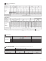
6HYDRAULICS CHARACTERISTICS
LF050
Note: Max flow rates are measured with Δp= 0,5 bar and viscosity 32mm2/s. In case of different conditions see section
For a correct sizing of the filter, it is suggested not to exceed 750 l/min to limit the maximum speed of the fluid in connecting pipes
11
SFRS-10, SFRS-20
FILTRATION
PLUS
Filter size 10 20
Port size code 00 01, 41 00 01 02, 42 03
Ports dimension G1/2” G3/4”
SAE12 G1/2” G3/4” G1”, SAE16 G1 1/4”
Filter length ABABABCDABCDABCDABCD
Max flow
(l/min)
at Δp 0,5 bar
-see note-
F06 14 36 15 38 32 50 66 82 35 57 93 100 35 58 93 133 36 62 93 135
F10 30 54 31 58 48 65 83 100 52 77 138 125 53 78 138 195 56 90 140 200
F25 48 73 50 80 58 79 96 110 67 97 189 141 67 100 189 240 75 125 200 260
C10 70 87 76 97 75 88 102 110 90 111 216 146 92 115 216 263 113 160 225 277
C25 75 94 92 105 90 105 114 120 115 138 288 163 118 144 288 300 168 243 305 300
Max operating pressure 8 bar
Direction of filtration See the arrow on the filter head
SFRS-30, SFRS-40
Filter size 30 40
Port size code 02 03 04 03 04 05, 45
Ports dimension G1” G1 1/4” G1 1/2”
SAE24 G1 1/4” G1 1/2” G2”, SAE32
Filter length ABABABABCDEABCDEABCDE
Max flow
(l/min)
at Δp 0,5 bar
-see note-
F06 180 190 175 185 180 190 203 286 310 233 430 210 300 330 240 460 210 310 338 245 500
F10 250 260 250 270 270 280 314 429 492 353 540 340 478 565 374 607 340 500 594 387 640
F25 265 275 280 293 290 310 340 495 525 386 590 370 570 611 412 708 370 600 650 430 750
C10 280 290 311 315 326 330 365 515 546 401 606 400 597 642 430 732 400 630 679 446 780
C25 330 355 380 390 400 409 473 594 640 495 648 536 714 782 540 790 536 750 800 564 800
Max operating pressure 8 bar
Direction of filtration See the arrow on the filter head

For the filter sizing it is necessary to consider the Total Δp at the maximum flow at which the filter must work.
The Total Δp is given by the sum of filter head Δp plus filter bowl Δp plus the filter element Δp:
Total Δp = filter head Δp + filter bowl Δp + filter element Δp
In the best conditions the total Δp should not exceed 0,5 bar
See below sections to calculate the Δp of filter head and Δp of the filter element
SFRS-10 SFRS-20
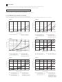
9 FILTERS SIZING
9.1 Q/Δp DIAGRAMS OF FILTER HEAD + FILTER BOWL
The pressure drop mainly depends on the ports size and fluid density
In the following diagrams are reported the Δp characteristics based on mineral oil with density 0,86 kg/dm3 and viscosity 32 mm2/s
Flow rate [l/min]
Pressure drop [bar]
020 40
60
80 100
Flow rate [l/min]
Pressure drop [bar]
0 20 40 60 80 100
Flow rate [l/min]
060 120
180
240 300
Pressure drop [bar]
Flow rate [l/min]
Pressure drop [bar]
0 100 200 300 400 500
SFRS-20
SFRS-30
1 = SFRS-10-*-00 (G 1/2”) 3 = SFRS-20-*-00 (G 1/2”)
4 = SFRS-20-A-01 (G 3/4”)
SFRS-20-B-01 (G 3/4”)
9 = SFRS-30-*-02 (G 1”)
10 = SFRS-30-*-03 (G 1 1/4”)
14 = SFRS-40-A-05 (G 2”)
SFRS-40-D-45 (G 2”)
SFRS-40-A-45 (SAE-32)
SFRS-40-D-45 (SAE-32)
6 = SFRS-20-C-01 (G 3/4”)
SFRS-20-D-01 (G 3/4”)
8 = SFRS-20-*-03 (G 1 1/4”)
16 = SFRS-40-B-05 (G 2”)
SFRS-40-C-05 (G 2”)
SFRS-40-E-05 (G 2”)
SFRS-40-B-45 (SAE-32)
SFRS-40-C-45 (SAE-32)
SFRS-40-E-45 (SAE-32)
1
25
4
8
7
11
10
Flow rate [l/min]
0.2
0.3
0.5
0.6
0120 240
360
480 600
0.1
0.4
Pressure drop [bar]
SFRS-40
13
12
0.2
0.3
0.5
0.6
0.1
0.4
0.10
0.15
0.25
0.30
0.05
0.20
0.2
0.3
0.5
0.6
0.1
0.4
14
Flow rate [l/min]
0120 240
360
480 600
Pressure drop [bar]
SFRS-40
15
16
0.2
0.3
0.5
0.6
0.1
0.4
2 = SFRS-10-*-01 (G 3/4”)
SFRS-10-*-41 (SAE-12)
11 = SFRS-30-*-04 (G 1 1/2”)
SFRS-30-*-44 (SAE-24)
5 = SFRS-20-A-02 (G 1”)
SFRS-20-B-02 (G 1”)
SFRS-20-A-42 (SAE-16)
SFRS-20-B-42 (SAE-16)
12 = SFRS-40-A-03 (G 1 1/4”)
SFRS-40-D-03 (G 1 1/4”)
13 = SFRS-40-A-04 (G 1 1/2”)
SFRS-40-D-04 (G 1 1/2”)
15 = SFRS-40-B-04 (G 1 1/2”)
SFRS-40-C-04 (G 1 1/2”)
SFRS-40-E-04 (G 1 1/2”)
0.10
0.15
0.25
0.30
0.05
0.20
3
6
7 = SFRS-20-C-02 (G 1”)
SFRS-20-D-02 (G 1”)
SFRS-20-C-42 (SAE-16)
SFRS-20-D-42 (SAE-16)
9

Gradient coefficient Gc of SFRS filter elements
Examples:
1) calculation of Total Δp for filter type SFRS-20-B-F10-02-R at Q = 50 l/min and viscosity 46 mm2/s (filter element SPRS-20-B-F10)
Δp of filter head + filter bowl = 0,03 bar
Gc = 5,27 mbar/(l/min)
Filter element Δp = 50 X 5,27 X46 = 0,379 bar
1000 32
Total Δp = 0,03 + 0,379 = 0,40 bar
2) calculation of Total Δp of filter type SFRS-40-C-F25-05-R at Q = 500 l/min and viscosity 46 mm2/s (filter element SPRS-40-C-F25)
Δp of filter head + filter bowl = 0,13 bar
Gc = 0,42 mbar/(l/min)
Filter element Δp = 500 X 0,42 X46 = 0,302 bar
1000 32
Total Δp = 0,13 + 0,302 = 0,43 bar
LF050
Filter element size 10 20 30 40
Filter element length A B A B C D A B A B C D E
Filtration rating Gc Gradient coefficient
F06 33.84 12.28 13.85 7.80 5.09 3.34 2.43 2.25 2.40 1.49 1.32 1.80 0.80
F10 15.68 7.32 8.65 5.27 3.19 1.94 1.31 1.21 1.11 0.74 0.52 0.88 0.43
F25 8.81 4.28 6.32 3.60 2.06 1.26 1.10 1.00 0.96 0.51 0.42 0.71 0.24
C10 4.83 2.74 4.09 2.70 1.64 1.06 0.85 0.83 0.82 0.45 0.36 0.64 0.20
C25 4.13 2.06 2.52 1.41 0.82 0.42 0.39 0.35 0.34 0.23 0.12 0.26 0.10
10 BY -PASS VALVE - based on mineral oil ISO VG46 at 50°C (viscosity = 32 mm2/s)
Q/Δp diagrams of flow trough the by pass valve
Flow rate [l/min]
050 100
150
200 250
Pressure drop [bar]
SFRS-10
SFRS-20
3
4.5
6
1.5
Flow rate [l/min]
0120 240
350
480 600
Pressure drop [bar]
SFRS-30
SFRS-40
3
4.5
6
1.5
9.2 FILTER ELEMENT Δp
The pressure drop through the filter depends to:
• size of filter element
• filtration rating
• fluid viscosity
The Δp of filter element is given by the formula:
Δp of filter element = Q X Gc X Viscosity
1000 32
Q = working flow (l/min)
Gc = Gradient coefficient (mbar/(l/min)).
The Gc values are reported in the following table
Viscosity = effective fluid viscosity in the working conditions (mm2/s)

Code A B1 B2 B3 D1 D2 D3 H1 H2 H3 H4 R
(element removal) Mass (Kg)
SFRS-10-A 1/2” BSPP
3/4” BSPP
SAE-12
89 25 51 67,5 24 67 82 60 8 22 150 0,45
SFRS-10-B 155 220 0,60
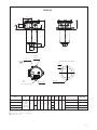
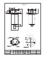
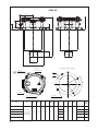
11 INSTALLATION DIMENSIONS OF SFRS FILTERS [mm]
Clogging
indicator port
A
B2
B1
D1
D2
D3
H4
H1 H2
H3
B3
SFRS-10
FILTER MOUNTING SURFACE
R
2 holes
Ø7,4 for SFRS-10 n°2 M6 for SFRS-10
n°3 bolts
Locking torque
10Nm
Nameplate
10
IN
OUT
(1) SAE-12 thread size 1” 1/16-12-UN-2B

(1) SAE-16 thread size 1” 5/16-12-UN-2B
(2) For port size 1/2”, 3/4”, 1” and SAE-16
(3) For port size 1 1/4”
Code A B1 B2 B3 D1 D2 D3 H1 H2 H3 H4 R
(element removal) Mass (Kg)
SFRS-20-A 1/2” BSPP
3/4” BSPP
1” BSPP
1 1/4” BSPP
SAE-16 (1)
115
28,5
67 88,5 40 87
92
73 11 24
170 0,80
SFRS-20-B 139 220 0,90
SFRS-20-C 32 219 295 1,10
SFRS-20-D 323 400 1,30
Clogging
indicator port
A
B2
B1
D1
D2
D3
H4
H1 H2
H3
B3
SFRS-20
FILTER MOUNTING SURFACE
R
Ø9,3
2 holes
n°2 M8
n°3 bolts
Locking torque
10Nm
(2)
(3)
LF050
Nameplate
10
IN
OUT

B1
D1
SFRS-30
FILTER MOUNTING SURFACE
75°
120°
Ø11,5
3 holes
n°3 M10
Clogging
indicator port
n°3 bolts
Locking torque
20Nm
Code A B1 B2 B3 D1 D2 D3 H1 H2 H3 H4 R
(element removal) Mass (Kg)
SFRS-30-A 1” BSPP
1 1/4” BSPP
1 1/2” BSPP
SAE-24 (1)
175 35 95 130 40 129 234 90 11 30 320 2,10
SFRS-30-B 263 360 2,40
A
B2
D2
D3
H4
H1 H2
H3
B3
R
Nameplate
13
IN
OUT
(1) SAE-24 thread size 1” 7/8-12-UN-2B

B1
D1
SFRS-40
FILTER MOUNTING SURFACE
30°
90°
Ø11,5 4 holes n°4 M10
Clogging
indicator port
n°4 bolts
Locking torque
20Nm
A
B2
D2
D3
H4
H1 H2
H3
B3
R
Code A B1 B2 B3 D1 D2 D3 H1 H2 H3 H4
R
(element
removal)
Mass
(Kg)
SFRS-40-A
1 1/4” BSPP
1 1/2” BSPP
2” BSPP
SAE-32 (2)
220 42 115 175 65 174
165
105 11 37
270 3,20
SFRS-40-B 224 330 3,60
SFRS-40-C 274 380 4,20
SFRS-40-D (1) 224 330 3,60
SFRS-40-E 424 530 4,00
LF050
Nameplate
(1) Filter type SFRS-40-D has the same length of SFRS-40-B but it uses filter elements with smaller internal diameter
(2) SAE-32 thread size 2” 1/2-12-UN-2B
13
IN
OUT

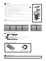
12 ACCESSORIES - to be ordered separately
Following accessories can be assembled on return filters type SFRS-20, SFRS-30 and SFRS-40 (not available for SFRS-10) to avoid the foam or
air/oil emulsion inside the tank caused by the return flow.
The discharge ending pipes DSC-END-* are used to extend the outlet port of the SFRS filters below the oil level in the tank.
They are available with length 250 (200 mm for SFRS-40) and 500 mm
The diffusers DIFF-SFRS are used in case of high flow rates to evenly distribute the return flow inside the tank.
They can be mounted directly on the filter bowl or using the connecting pipes CONN-END-*, available with lengths of 250 (200 for SFRS-40)
and 500 mm.
Discharge ending pipe
MODEL CODE OF DISCHARGE ENDING PIPES
DSC-END -
Pipe length for SFRS-20 and SFRS-30:
250 = 250 mm
500 = 500 mm
Pipe length for SFRS-40:
200 = 200 mm
500 = 500 mm
250
Filter type:
SFRS-20/30 = for SFRS-20 and SFRS-30
SFRS-40 = for SFRS-40
SFRS-20/30
Diffuser
MODEL CODE OF DIFFUSERS
DIFF -
Filter type:
SFRS-20/30 = for SFRS-20 and SFRS-30
SFRS-40 = for SFRS-40
SFRS-20/30
Connecting ending pipe
MODEL CODE OF CONNECTING ENDING PIPES
CONN-END -
Pipe length for SFRS-20 and SFRS-30:
250 = 250 mm
Pipe length for SFRS-40:
200 = 200 mm (for SFRS-40)
500 = 500 mm (for SFRS-40)
250
Filter type:
SFRS-20/30 = for SFRS-20 and SFRS-30
SFRS-40 = for SFRS-40
SFRS-20/30
PIPE LENGTH
DIFFUSER
CODE
DIMENSIONS
ABC
DIFF-SFRS-20, DIFF-SFRS-30 30 45 75
DIFF-SFRS-40 35 70 105
AB
DISCHARGE ENDING PIPE CONNECTING ENDING PIPE DIFFUSER
DIFFUSER DIMENSIONS
PIPE LENGTH
øC
LF050

14 DIMENSIONS OF CLOGGING INDICATORS
15 INSTALLATION AND COMMISSIONING
Verify that the tank flange with the filter mounting surface is clean and free of scratches.
Install the filter on the tank cover using the fixing holes on the filter head.
Connect the IN port of the filter to the system return pipe.
The OUT port of the filter must end under the oil level to avoid foam or air/oil emulsion inside the tank.
At this purpose specific accessories as connecting pipes, discharge ending pipes ad flow
diffusers can be fit on the filter OUT port see section
Make sure that there is enough space above the filter, for the replacement of the filter element,
see dimension “R” at section
Never run the system without the filter element.
For filters ordered with clogging indicator, code E or V:
• remove the steel plug from the indicator port on the filter head
• install the clogging indicator and lock it at the specified torque
During the cold start up (fluid temperature lower than 30°C), a false clogging indicator signal can
be given due to the high fluid viscosity.
12
11
35
75
40
50
CIA-E
CIA-E/UL CIA-V
27
Locking torque 20Nm 12
Locking torque 10 Nm
Electric connector
DIN 43650
Black colour
PG7
flow
direction
fixing
holes
25
G 1/8”
1/8” G. Cyl.
Note: add sealant on indicator threads
13 CHARACTERISTICS OF CLOGGING INDICATORS
Model code CIA-E electrical CIA-V visual
Switching pressure 2 bar green sector
red sector
Switching tolerance at 20°C ± 10% of switching pressure -
Electric connection Electric plug connection as per DIN 43650 with
cable gland type PG7 -
Power supply 14 VDC ÷ 30 VDC 125 VAC ÷ 250 VAC
Max current - resistive (inductive) 4 A (3 A) ÷ 3 A (2 A) 5 A (3 A) ÷ 3 A (2 A)
Fluid temperature -25°C ÷ +100°C -25°C ÷ +100°C
Protection degree according to DIN 40050 IP65 with mating connector -
Hydraulic connection G1/8” BSP G1/8” BSP
Duty factor 100% 100%
Mass (Kg) 0,16 0,04
Electric scheme /
Hydraulic symbol
The electric scheme shows
the switch position in case
of clean filter element
1 C 2 NC
3 NO
= 0 ÷ 3 bar
= 3 ÷ 10 bar
30
G 1/8”
12
Locking torque 10 Nm
40
CIA-V/P
(available on request)
IN
OUT
steel plug
to be removed
to install
clogging indicator

08/23
16 MAINTENANCE
The filter element must be replaced as soon as the clogging indicator switches to highlight the filter
clogged condition
For filters without clogging indicator, the filter element must be replaced according to the system man-
ufacturer’s recommendations.
Select the new filter element according to the model code reported on the filter nameplate, see section
For the replacement of the filter element, proceed as follow:
• switch-off the system and make sure that there is no residual pressure in the filter line (i.e. pressur-
ized tank); the filter has no pressure bleeding device
•
pay attention to the fluid and filter surface temperature. Always use suitable gloves an protection glasses
• remove the cover from the filter head by releasing the bolts
• remove the spring and the bowl
• remove the dirty filter element pulling it upward carefully
• clean the bowl
• install the bowl after having checked the good condition of the seal
• insert the new filter element over the spigot in the filter bowl; the filter element includes the by-pass
valve
• install the spring
• mount the cover and lock the relevant bolts after having checked the good condition of the seal
17
WARNING: The dirty filter elements cannot be cleaned and re-used. They are classified as
“dangerous waste material”, then they must be disposed of by authorized
Companies, according to the local laws.
AT-1193
Filter Element:
Model code of complete filter
Model code of filter element
Filter matrix code
SFRS-10-A-F10-01-R-W ** /PE
SPRS-10-A-F10 ** /PE
16.1 SEALS KIT
16.2 SPARE SPRING
Filter type Seal kit code
SFRS-10 MO-1246
SFRS-20 MO-1247
SFRS-30 MO-1248
SFRS-40 MO-1249
18 RELATED DOCUMENTATION
LF010 Fluid contamination
LF020 Filtration guidelines
17.1 IDENTIFICATION OF FILTER ELEMENT
Model code of filter element
Filtration Plus identification
Filter type Seal kit code (NBR) Seal kit code (FKM) Seal kit composition
SFRS-10 GUARN SFRS-10 GUARN SFRS-10 /PE ++
SFRS-20 GUARN SFRS-20 GUARN SFRS-20 /PE ++
SFRS-30 GUARN SFRS-30 GUARN SFRS-30 /PE ++
SFRS-40 GUARN SFRS-40 GUARN SFRS-40 /PE ++
17 FILTER IDENTIFICATION NAMEPLATE
-
 1
1
-
 2
2
-
 3
3
-
 4
4
-
 5
5
-
 6
6
-
 7
7
-
 8
8
-
 9
9
-
 10
10
-
 11
11
-
 12
12


Atos LF050-IN Owner's manual
- Type
- Owner's manual
- This manual is also suitable for
Ask a question and I''ll find the answer in the document
Finding information in a document is now easier with AI
Related papers
Other documents
-
Texas Instruments MSC1210: User manual
-
Intel 8XC196Jx User manual
-
-
Lincoln Electric D1.8 User manual
-
-
-
NXP P89LPC9103FTK User guide
-
Philips P89LPC903FD User manual
-
-
NXP P89LPC9151FDH User guide