Vertiv Knurr DIS - I User manual
- Category
- Power distribution units (PDUs)
- Type
- User manual
This manual is also suitable for

Vertiv Knürr DIS Load Meter
Module with Remote Monitoring –
Power Distribution Units
Vertiv Knürr DIS
Strommessmodul mit
Fernüberwachung
- Stromverteilungseinheiten
Vertiv Knürr DIS Module de
mesure de courant avec contrôle
à distance - Unités de distribution
de courant
Operating Instructions / Bedienungsanleitung / Notice d’utilisation

2Vertiv | Vertiv Knürr DIS Load Meter Module with Remote Monitoring – Power Distribution Units | 03.300.999.8 I 10/18
Bitte lesen
1.1 Allgemeine Informationen .................. 3
1.2 Gewährleistung ............................ 3
1.3 Service .................................... 3
Technische Beschreibung
2.1 Konzeption ................................ 4
2.2 Funktion................................... 4
Installation und
Inbetriebnahme
3.1 Anschluss an das Netzwerk
über DHCP ............................... 6
3.2 Anschluss an das Netzwerk über
eine statische IP Adresse .................. 7
Betrieb
4.1 Zugriff über das Netzwerk ................. 9
4.2 Einstellen der Grenzwerte................. 10
4.3 Verwendung der Messanzeige............. 12
4.4 Einstellung ............................... 15
4.5 SNMP .................................... 17
4.6 Zugriff auf die
Ereignisprotokollierungsseite...............19
4.7 Einstellung der Systemzeit ................20
4.8 Einstellung des CLI Zugriffs ...............20
4.9 Einstellung Modbus.......................22
4.10 Firmware ................................. 26
4.11 Resetmöglichkeiten: Neustart und
Zurücksetzen auf Werkseinstellung........ 27
4.12 Anzeigestatusinformation ................. 29
Inhalt
Please read
1.1 General Information........................ 3
1.2 Warranty .................................. 3
1.3 Service .................................... 3
Technical Description
2.1 Design .................................... 4
2.2 Function................................... 4
Installation and
Commissioning
3.1 Network connection
via DHCP ................................. 6
3.2 Network connection via static IP address .... 7
Operation
4.1 Access via the network .................... 9
4.2 Setting limit values ....................... 10
4.3 Using the meter display................... 12
4.4 Setting ................................... 15
4.5 SNMP .................................... 17
4.6 Access to the event logging page ..........19
4.7 Setting system time.......................20
4.8 Setting CLI access ........................20
4.9 Setting Modbus...........................22
4.10 Firmware .................................26
4.11 Reset options: Restart and restore
factorysettings........................... 27
4.12 Monitor status information ................ 29
Table of Contents
À lire
1.1 Informations d’ordre général ............... 3
1.2 Garantie ................................... 3
1.3 Service .................................... 3
Description technique
2.1 Conception ................................ 4
2.2 Fonction................................... 4
Installation et
mise en service
3.1 Raccordement au réseau via DHCP ........ 6
3.2 Raccordement au réseau via
une adresseIP statique .................... 7
Exploitation
4.1 Accès via le réseau ........................ 9
4.2 Réglage des seuils ........................ 10
4.3 Utilisation de l’affichage de mesure........ 12
4.4 Réglage .................................. 15
4.5 SNMP .................................... 17
4.6 Accès à la page d’enregistrement
des événements ...........................19
4.7 Réglage de l’heure du système ............20
4.8 Réglage de l’accès CLI ....................20
4.9 Réglage Modbus..........................22
4.10 Firmware ................................. 26
4.11 Possibilités de redémarrage:
Redémarrage et rétablissement
des réglages par défaut ................... 27
4.12 Informations du statut d’affichage ......... 29
Sommaire

3Vertiv | Vertiv Knürr DIS Load Meter Module with Remote Monitoring – Power Distribution Units | 03.300.999.8 I ECR. No. 18618 I 10/18
General Information
Copyright
All rights to this handbook remain exclusively with
Vertiv Integrated Systems. Reprinting or duplication
of these operating instructions in whole or in part
is only permitted if the source of information is
indicated.
Technical status
The technical status of the handbook is 05/2017.
Vertiv Integrated Systems reserves the right
to change the design, software, or components
without notice, or to use equivalent parts other
than those illustrated here if this is to serve
technical progress, and
–to change the information provided in this
handbook.
Liability
Vertiv Integrated Systems cannot be held liable for
the completeness or correctness of the information
provided.
In particular, we assume no liability whatsoever for
damages resulting from improper use or accidental
misuse.
The other documentation should also
beused.
Note
This manual is a supplement to the main
manual "Knurr® DI-Strip Rack PDU – Power
Distribution Units".
Safety instructions in this manual must be
followed.
Warranty
Vertiv Integrated Systems GmbH grants a warranty
of 24months on all mechanical and electrical
components. Additional details can be found in the
General Terms and Conditions issued by Vertiv
Integrated Systems.
Service
Vertiv Integrated Systems GmbH provides you with
technical service, which is available to answer all of
your questions. Please contact:
Vertiv Integrated Systems GmbH
Mariakirchener Strasse 38
D-94424 Arnstorf
& + 800 1155 4499
E-mail eoc@vertivco.com
Bitte lesen
Allgemeine Informationen
Urheberrecht
Alle Rechte an diesem Handbuch gehören
allein Vertiv Integrated Systems. Nachdruck und
Vervielfältigung dieser Bedienungsanleitung im
Ganzen oder zum Teil sind nur dann erlaubt, wenn
die Informationsquelle genannt wird.
Technischer Stand
Der technische Stand des Handbuchs ist 05/2017.
Vertiv Integrated Systems behält sich das Recht vor,
ohne Vorankündigung die Konzeption, die Software
oder die Komponenten zu ändern, oder andere
gleichwertige Teile als jene zu verwenden, die hier
angezeigt werden, wenn dies dem technischen
Fortschritt dient, und
–die Informationen zu ändern,
die in diesem Handbuch angeführt sind.
Haftung
Vertiv Integrated Systems kann weder für die
Vollständigkeit, noch für die Richtigkeit der ange-
führten Informationen haftbar gemacht werden.
Wir übernehmen im Speziellen keinerlei Haftung für
Schäden, die durch die falsche Verwendung oder
Fehlbedienung entstehen.
Benutzen Sie auch die anderen
Dokumentationen
1.1
Hinweis
Dieses Manual ist eine Ergänzung zum
Hauptmanual "Knurr® DI-Strip Rack PDU –
Steckdosenleisten".
Sicherheitshinweise aus diesem Manual
müssen beachtet werden.
Gewährleistung
Vertiv Integrated Systems GmbH gewährt
eine Gewährleistung von 24Monaten auf alle
mechanischen und elektrischen Bauteile. Weitere
Details finden Sie in den aufgeführten allgemeinen
Geschäftsbedingungen von Vertiv Integrated
Systems.
1.2
Service
Der technische Dienst der Vertiv Integrated
Systems GmbH steht Ihnen für alle Fragen gerne zur
Verfügung. Bitte wenden Sie sich an:
Vertiv Integrated Systems GmbH
Mariakirchener Straße 38
D-94424 Arnstorf
& + 800 1155 4499
E-Mail eoc@vertivco.com
1.3
Informations d’ordre général
Droit d’auteur
Tous les droits relatifs au présent manuel sont
propriété exclusive de Vertiv Integrated Systems.
La réimpression et la copie de la présente notice
d’utilisation, en tout ou partie, ne sont autorisées
que si la source d’information est citée.
Niveau technique
Le niveau de la technique est celui du mois de
mai2017. Vertiv Integrated Systems se réserve
le droit de modifier, sans annonce préalable, la
conception, le logiciel ou les composants, ainsi que
d’utiliser toute partie similaire à celles présentées
ici, si une telle modification ou utilisation sert à
l’évolution technique.
–Vertiv Integrated Systems se réserve également
le droit de modifier les informations stipulées
dans le présent manuel.
Responsabilité
Vertiv Integrated Systems décline toute
responsabilité concernant l’exhaustivité et la
véracité des informations stipulées.
Nous déclinons notamment toute responsabilité en
cas de dommages liés à une mauvaise utilisation ou
à une utilisation abusive.
Veuillez utiliser également les autres
documentations
Remarque
Le présent manuel complète le manuel
principal «Knurr® DI-Strip Rack PDU –
rallonges multiprises».
Les consignes de sécurité de ce manuel
doivent être respectées.
Garantie
Vertiv Integrated Systems GmbH octroie
une garantie de 24mois sur les composants
mécaniques et électriques. Vous trouverez de plus
amples détails dans les Conditions générales de
vente de Vertiv Integrated Systems.
Service
Le service technique de Vertiv Integrated Systems
GmbH reste à votre disposition pour toute question.
Veuillez vous adresser à:
Vertiv Integrated Systems GmbH
Mariakirchener Straße 38
D-94424 Arnstorf
& + 800 1155 4499
E-mail [email protected]
Please read À lire

4Vertiv | Vertiv Knürr DIS Load Meter Module with Remote Monitoring – Power Distribution Units | 03.300.999.8 I ECR. No. 18618 I 10/18
Technische Beschreibung
Konzeption
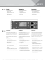
Steuerungs- und Anzeigeelemente:
–Auswahltaste EINGANG (A1),
–Reset-Taste (A2),
–Auswahltaste Attribute (A3),
–Hauptmenü (A4),
–Einheit (A5),
–Messwert (A6),
–Netzwerkanschluss - RJ45 (A7),
–Serieller Anschluss RS485 - RJ45 (A8).
2.1
A
Funktion
Das Messmodul der Stromverteilungseinheit misst
elektrische Werte pro Eingang.
Die Messwerte können entweder direkt am LCD
Bildschirm der PDU oder über ein Netzwerk in
einem Fernmodus angezeigt werden.
Verschieden Schwellwerte können eingestellt wer-
den und melden dem Benutzer den Status der PDU
lokal oder remote.
Tastenfunktionen
• Taste A1 (Select Input):
Entsprechenden Eingang wählen (falls die PDU
mehrere Eingänge hat)
Anzeige Netzwerkeinstellung
• Taste A2 (Reset):
Reset-Möglichkeiten sind in 4.11 beschrieben.
• Taste A3 (Select Attribute / Rotate Display):
- Taste kurz drücken < 1 s: Die verschiedenen
Messwerte werden angezeigt (Bild B)
- Taste lang drücken > 1s: Rotation der
Anzeige in 90° Schritten und Änderung der
Hintergrundbeleuchtung hell / dunkel
• Taste A1 während Power-up oder nach
einem Reset drücken. Dadurch wird der
Netzwerkport von DHCP auf eine feste stati-
scher IP Adresse umgeschaltet (192.168.0.1)
2.2
Description technique
Conception
Éléments de commande et d’affichage
–Touche de sélection ENTRÉE (A1),
–Touche de redémarrage (A2),
–Touche de sélection Attribut (A3),
–Menu principal (A4),
–Unité (A5),
–Valeur mesurée (A6),
–Raccordement réseau - RJ45 (A7),
–Raccordement sériel RS485 - RJ45 (A8).
Fonction
Le module de mesure de l’unité de distribution de
courant mesure les valeurs électriques par entrée.
Les valeurs mesurées peuvent être affichées sur
l’écranLCD du PDU ou sur un mode à distance.
Divers seuils peuvent être paramétrés. Ils indiquent
à l’utilisateur le statut du PDU localement ou à
distance.
Fonctions des touches
• ToucheA1 (Select Input):
Sélectionner l’entrée correspondante (si le PDU
dispose de plusieurs entrées)
Affichage réglage par défaut du réseau
• ToucheA2 (Reset):
Possibilités de redémarrage décrites en
section4.11.
• ToucheA3 (Select Attribute / Rotate Display):
- Pression courte de la touche <1s: Les
différentes valeurs mesurées sont affichées
(imageB)
- Pression longue de la touche >1s: Rotation
de l’affichage par pas de 90° et changement
du rétro-éclairage sombre/clair
• Appuyer sur la toucheA1 lors du démarrage
ou après un redémarrage. Cela fait passer
le port réseau du DHCP à une adresseIP
statique fixe (192.168.0.1)
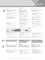
Technical Description
Design
Control and display elements:
–INPUT selection button (A1),
–Reset button (A2),
–Attribute selection button (A3),
–Main menu (A4),
–Unit (A5),
–Measured value (A6),
–Network connection - RJ45 (A7),
–Serial connection RS485 - RJ45 (A8).
Function
The meter module of the power distribution unit
measures electrical values for each input.
The measured values can be displayed directly on
the LCD screen of the PDU or via a network in a
remote mode.
Various threshold values can be set, which alert
the user to the status of the PDU either locally or
remotely.
Button functions
• Button A1 (Select Input):
Select corresponding input (if the PDU has
several inputs)
Network setting display
• Button A2 (Reset):
Reset options are described in 4.11.
• Button A3 (Select Attribute / Rotate Display):
- Tap button < 1s: The various measured
values are displayed (Image B)
- Press and hold button > 1s: Display rotation
in 90° steps and backlight adjustment
light/dark
• Press Button A1 during power-up or after a
reset. This switches the network port from
DHCP to a fixed static IP address (192.168.0.1).

5Vertiv | Vertiv Knürr DIS Load Meter Module with Remote Monitoring – Power Distribution Units | 03.300.999.8 I ECR. No. 18618 I 10/18
Anzeigebereich
–Anzeige des Echt-Effektivwert [A] (ein- oder
dreiphasig)
–Nach 10 Minuten schaltet das Modul auf
den Energiesparmodus um (derBildschirm
wird schwarz). Die Anzeige kann durch die
Betätigung einer beliebigen Taste aktiviert
werden.Bei Auftreten einer Warnung oder
eines Alarms geschieht dies selbsttätig.
Technische Daten
–Messwerte:
• Strom pro Phase
• Spannung pro Phase
• Scheinleistung
• Wirkleistung
• Energieverbrauch
• Leistungsfaktor
• Frequenz
–Leistungsaufnahme: < 4 W
–Messgenauigkeit:
• Strom: 1,5 % ( I = 1 - 10 %)
• Strom: 1 % (I = 10 - 100 %)
• Spannung: 1 %
• Leistung: 2 %
• Energie: 2 %
• Leistungsfaktor: 1 %
• Frequenz: 1 %
–Messauflösung:
• Strom: 0,01 A
• Spannung: 0,1 V
• Leistung: 0,01 kW, 0,01 kVA
• Energie: 0,1 kWh / MWh / GWh
• Leistungsfaktor: 0,01
• Frequenz: 0,01 Hz
B
Technische Beschreibung
Display area
–Display the real effective value [A] (single-
orthree-phase)
–After 10 minutes the module switches over to
the power-saving mode (display goes black).
Pressing any button will activate the display.
A warning or alarm will automatically activate
the display.
Technical data
–Measured values:
• Current per phase
• Voltage per phase
• Apparent power
• Effective power
• Energy consumption
• Power factor
• Frequency
–Power consumption: < 4 W
–Measurement accuracy:
• Current: 1.5% ( I = 1 - 10%)
• Current: 1% ( I = 10 - 100%)
• Voltage: 1%
• Output: 2%
• Energy: 2%
• Power factor: 1%
• Frequency: 1%
–Measurement resolution:
• Current: 0.01 A
• Voltage: 0.1 V
• Output: 0.01 kW, 0.01 kVA
• Energy: 0.1 kWh / MWh / GWh
• Power factor: 0.01
• Frequency: 0.01 Hz
Technical Description
Zone d’affichage
–Affichage de la valeur réelle effective [A]
(monophasé ou triphasé)
–Après 10minutes, le module passe en mode
économie d’énergie (l’écran devient noir).
L’affichage peut être activé en appuyant sur
n’importe quelle touche. En cas d’alerte ou
d’alarme, son activation est automatique.
Caractéristiques techniques
–Valeurs de mesure:
• Intensité par phase
• Tension par phase
• Puissance apparente
• Puissance réelle
• Consommation d’énergie
• Coefficient de puissance
• Fréquence
–Consommation de puissance: <4W
–Précision de mesure:
• Intensité: 1,5% ( I=1 - 10%)
• Intensité: 1% (I = 10 - 100%)
• Tension: 1%
• Puissance: 2%
• Énergie: 2%
• Coefficient de puissance: 1%
• Fréquence: 1%
–Précision de mesure:
• Intensité: 0,01A
• Tension: 0,1V
• Puissance: 0,01kW, 0,01kVA
• Énergie: 0,1kWh / MWh / GWh
• Coefficient de puissance: 0,01
• Fréquence: 0,01Hz
Description technique

6Vertiv | Vertiv Knürr DIS Load Meter Module with Remote Monitoring – Power Distribution Units | 03.300.999.8 I ECR. No. 18618 I 10/18
Installation und Inbetriebnahme
Anschluss an das Netzwerk
über DHCP
• Vergewissern Sie sich, dass der DHCP Server
MAC Adressen (Media Access Control) unter-
stützt.Einige Netzwerkadministratoren verbieten
aus Sicherheitsgründen den Zugriff auf das
DHCP Netzwerk für Geräte mit einer unbekann-
ten MAC Adresse.
• Im Auslieferzustand ist die Netzwerkschnittstelle
auf DHCP konfiguriert. Hält man die Taste A1
während des Einschaltvorgangs oder eines
Hadware-Reset (über Taste A2) gedrückt, so
wechselt die PDU auf eine statische IP Adresse
(192.168.0.1). Der Auslieferzustand DHCP bleibt
jedoch fest eingestellt. Um dauerhaft auf eine
statische IP Adresse umzustellen muss die
Einstellung in der Software entsprechend umge-
setzt werden (Kapitel 3.2)
3.1
A
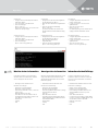
Installation and Commissioning
Network connection via
DHCP
• Make sure that the DHCP server supports MAC
addresses (media access control). For security
reasons, some network administrators forbid
access to the DHCP network from devices with
an unrecognized MAC address.
• The default configuration assigns the network
interface to DHCP. If you hold down Button A1
during the power-up phase or a hardware reset
(via Button A2), the PDU changes to a static
IP address (192.168.0.1). However, the default
configuration of DHCP remains. Toconvert
permanently to a static IP address, the
software settings must be changed accordingly
(Chapter3.2).
Installation et mise en service
Raccordement au réseau via
DHCP
• Assurez-vous que le serveurDHCP est
compatible avec les adresses MAC (Media
Access Control). Pour des raisons de sécurité,
certains administrateurs réseau interdisent
l’accès au réseauDHCP par les appareils dont
l’adresseMAC est inconnue.
• À la livraison, l’interface réseau du DHCP est
configurée. En maintenant la toucheA1 enfoncée
lors du processus de démarrage ou d’un
redémarrage forcé (via la toucheA2), le PDU
passe à une adresseIP statique (192.168.0.1).
L’état à la livraison du DHCP reste cependant
paramétré. Pour passer définitivement sur une
adresseIP statique, les réglages du logiciel
doivent être adaptés (chapitre3.2)
Informationen
Die IP Adresse die das Modul vom DHCP
Server bekommen hat kann am lokalen Display
der PDU abgelesen werden (durch Drücken
der Taste A1).
Informationen
Ändern Sie das Standard-Passwort admin für
Administratoren, nachdem Sie das Netzwerk
konfiguriert haben.
B
Information
The IP address that the module received from
the DHCP server can be read on the local dis-
play of the PDU (by pressing Button A1).
Information
After configuring the network, change the
standard password (admin) for administrators.
Informations
L’adresseIP que le module reçoit du
serveurDHCP peut être affichée à l’écran du
PDU (en appuyant sur la toucheA1).
Informations
Modifiez le mot de passe standard pour l’admi-
nistrateur après avoir configuré le réseau.

7Vertiv | Vertiv Knürr DIS Load Meter Module with Remote Monitoring – Power Distribution Units | 03.300.999.8 I ECR. No. 18618 I 10/18
Installation und Inbetriebnahme
Installation and Commissioning Installation et mise en service
Network conne ction via static
IP address
Request the following from your network admi-
nistrator:
–IP address that the PDU should use perma-
nently
–Subnet mask: Identifies the local segment of
the LAN (Local Area Network)
–Standard gateway: Address of a router or
computer in the network, which is used to
access other networks
Configure your computer with a static
IPaddress.
Choose a segment between 192.168.0.2 and
192.168.0.255 (for example, 192.168.0.5).
Do not use the address 192.168.0.1 because this is
the standard address for the meter module.
Select 255.255.255.0 for the subnet mask.
Leave the “Default gateway” checkbox empty.
Information
The default configuration assigns the network
interface to DHCP. If you hold Button A1 down
during the power-up phase or a hardware reset
(via Button A2), the PDU changes temporarily
to a static IP address (192.168.0.1).
Anschluss an das Netzw erk über
eine statische IP Adresse
Fordern Sie Folgendes bei Ihrem
Netzwerkadministrator an:
–IP Adresse, welche die PDU permanent nutzen
sollte
–Subnetzmaske: Identifiziert den lokalen
Abschnitt des LAN (Local Area Network)
–Standard-Gateway: Adresse eines Routers
oder eines Computers im Netzwerk, der
verwendet wird, um auf andere Netzwerke
zuzugreifen.
Konfigurieren Sie Ihren Computer auf eine
statische IP-Adresse.
Wählen Sie einen Bereich zwischen 192.168.0.2 und
192.168.0.255 (z.B. 192.168.0.5).
Verwenden Sie die Adresse 192.168.0.1 nicht, da
es sich dabei um die Standard-Adresse für das
Messmodul handelt.
Wählen Sie 255.255.255.0 für „Subnet mask“.
Lassen Sie das „Default gateway“ Kästchen leer.
Informationen
Im Auslieferzustand ist die Netzwerkschnittstelle
auf DHCP konfiguriert. Hält man die Taste A1
während des Einschaltvorgangs oder eines
Hadware-Reset (über Taste A2) gedrückt, so
wechselt die PDU vorübergehend auf eine stati-
sche IP-Adresse (192.168.0.1).
Raccordement au réseau via
une adresseIP statique
Demandez les points suivants à votre adminis-
trateur réseau:
–adresseIP que le PDU devrait utiliser en
permanence
–Masque de sous-réseau: identifie la section
locale du réseau local LAN (Local Area
Network)
–Passerelle standard: adresse d’un routeur ou
d’un ordinateur dans le réseau, utilisé pour
accéder à d’autres réseaux.
Configurez votre ordinateur sur une
adresseIP statique.
Sélectionnez un domaine entre 192.168.0.2 et
192.168.0.255 (p.ex. 192.168.0.5).
N’utilisez pas l’adresse 192.168.0.1, car il s’agit de
l’adresse standard pour le module de mesure.
Sélectionnez 255.255.255.0 pour le «masque
sous-réseau».
Laissez la case «Default gateway» (passerelle par
défaut) vide.
Informations
À la livraison, l’interface réseau du DHCP
est configurée. En maintenant la toucheA1
enfoncée lors du processus de démarrage ou
d’un redémarrage forcé (via la toucheA2),
lePDU passe provisoirement à une adresseIP
statique (192.168.0.1).
3.2
PDU anschließen und konfigurieren
• Verbinden Sie den Netzwerkport der PDU (A7)
mit dem Netzwerk Port des Computers.
• Starten Sie den Web-Browser des Computers
und geben Sie die IP Adresse des Messmoduls
192.168.0.1 in die Adresszeile des Web-
Browsers ein ((Verbindung über https).
–Wenn die Verbindung aufgebaut ist, zeigt der
Web-Browser die „Summary” Seite an.
C
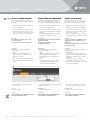
Connect and configure PDU
• Connect the network port of the PDU (A7) to the
network port of the computer.
• Start the computer’s web browser and
enter the IP address of the meter module
192.168.0.1 in the address line of the web
browser (https connection).
–Once the connection has been established, the
web browser displays the “Summary” page.
Raccorder et configurer le PDU
• Raccordez le port réseau du PDU (A7) au port
réseau de l’ordinateur.
• Démarrez le navigateur Internet de l’ordinateur
et saisissez l’adresseIP du module de mesure
192.168.0.1 dans la barre d’adresse du
navigateur Internet (connexion via https).
–Lorsque la connexion est établie, le navigateur
Internet affiche la page «Summary» (Sommaire).

8Vertiv | Vertiv Knürr DIS Load Meter Module with Remote Monitoring – Power Distribution Units | 03.300.999.8 I ECR. No. 18618 I 10/18
Installation und Inbetriebnahme
• Klicken Sie auf das Menü "SYSTEMS".
• Melden Sie sich als Administrator im
Strommessmodul an:
Geben Sie Ihren Benutzernamen und das
Passwort ein.
• Der Standard-Administratorname wird
als admin eingegeben
• Das Standard-Passwort wird
als admineingegeben
–Nachdem Sie sich angemeldet haben, zeigt der
Web-Browser die „Systems“ Seite an.
Informationen
Ändern Sie das Standard-Passwort admin für
Administratoren, nachdem Sie das Netzwerk
konfiguriert haben.
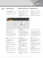
• Click on the SYSTEMS menu.
• Log in to the load meter module as an
administrator:
Enter your username and password.
• The standard administrator name is entered
as admin.
• The standard password is entered as admin.
–Once you have logged in, the web browser
displays the “Systems” page.
Information
After configuring the network, change the
standard password (admin) for administrators.
Installation and Commissioning
• Cliquez sur le menu «SYSTEMS» (SYSTÈMES).
• Connectez-vous au module de mesure du cou-
rant en tant qu’administrateur:
Saisissez votre nom d’utilisateur et le mot de
passe.
• Le nom d’administrateur standard est indiqué
comme admin
• Le mot de passe standard est indiqué
comme admin
–Une fois que vous êtes inscrit, le navigateur
Internet affiche la page «Systems» (Systèmes).
Informations
Modifiez le mot de passe standard pour
l’administrateur après avoir configuré le
réseau.
Installation et mise en service
• Vergewissern Sie sich, dass das „DHCP Enable”
Kästchen nicht angekreuzt ist.
• Geben Sie die Netzwerkeinstellung für das
Messmodul ein: IP Adresse, Subnet-Maske und
Standard-Gateway
• Speichern Sie Ihre Einstellungen mit "Submit".
• Make sure that the “DHCP enable” box is not
checked.
• Enter the network setting for the meter module:
IP address, subnet mask and standard gateway
• Save your settings by clicking “Submit”.
• Assurez-vous que la case «DHCP Enable»
(DHCP autorisé) n’est pas cochée.
• Saisissez les paramètres réseau du module de
mesure: adresseIP, masque sous-réseau et
passerelle standard
• Enregistrez vos réglages avec «Submit» (Valider).
D

9Vertiv | Vertiv Knürr DIS Load Meter Module with Remote Monitoring – Power Distribution Units | 03.300.999.8 I ECR. No. 18618 I 10/18
Zugriff über das Netzwerk
Wenn die PDU im Netzwerk angeschlossen ist,
können Sie von jedem beliebigen PC im Netzwerk
auf die PDU mit einem WEB-Browser zugreifen.
• Drücken Sie die Taste A1 (Select Input), um die
IP Adresse des Moduls zu prüfen".
• Geben Sie die IP Adresse des Strommessmoduls
in die Adresszeile desWeb-Browsers ein (Zugriff
über https).
–Wenn die Verbindung aufgebaut ist, zeigt der
Web-Browser die „Summary” Seite an.
4.1
Informationen
Die „Summary“ und „Info“ Seiten sind füralle
Benutzer erreichbar.
Für die anderen Seiten müssen sich
dieBenutzer anmelden.
Anmeldung
Entweder als Administrator (admin) oder
als User (user) anmelden:
–admin:
Administratoren können alle Seiten einsehen
und können alle Einstellungen editieren
(das Standard-Passwort für Administratoren
istadmin).
–user:
User können die „Summary“ und „Info“ Seiten
einsehen und können die Grenzwerte auf der
„Settings“ Seite definieren und editieren.
Access via the network
If the PDU is connected to the network, you can
access the PDU from a web browser on any PC in
the network.
• Press Button A1 (Select Input) to check the IP
address of the module.
• Enter the IP address of the load meter module in
the web browser’s address line (https access).
–Once the connection has been established, the
web browser displays the “Summary” page.
Information
The “Summary” and “Info” pages can be
accessed by all users.
For the other pages, users need to log in.
Logging in
Log in either as an administrator (admin) or
as a user (user):
–admin:
Administrators can see all pages and can
edit all settings (the standard password for
administrators is admin).
–user:
Users can see the “Summary” and “Info” pages
and can define and edit the limit values in the
settings.
Accès via le réseau
Lorsque le PDU est raccordé au réseau, vous
pouvez accéder au PDU depuis n’importe quel
ordinateur du réseau via le navigateur Internet.
• Appuyez sur la toucheA1 (sélectionner une
entrée) pour contrôler l’adresseIP du module.
• Saisissez l’adresseIP du module de mesure de
courant dans la barre d’adresse du navigateur
Internet (accès via https).
–Lorsque la connexion est établie, le navigateur
Internet affiche la page «Summary» (Sommaire).
Informations
Les pages «Summary» (Sommaire) et «Info»
(Informations) sont accessibles à tous les
utilisateurs.
Pour accéder aux autres pages, les utilisateurs
doivent se connecter.
Connexion
Se connecter en tant qu’administrateur (admin) ou
qu’utilisateur (user):
–Administrateur:
Les administrateurs peuvent accéder à toutes
les pages et éditer les réglages (le mot de passe
standard pour les administrateurs est admin).
–Utilisateur:
Les utilisateurs peuvent accéder aux
pages «Summary» (Sommaire) et «Info»
(Informations) et définir et éditer les seuils de la
page «Settings» (Réglages).
BetriebOperation Exploitation
A
• Geben Sie Benutzernamen und Passwort einund
klicken Sie auf „Login“.
Abmelden
• Klicken Sie auf „Logout“.
Informationen
Nach 10 Minuten ohne jede Aktivität findet
eine automatische Abmeldung statt.
• Enter the username and password, and then
click on “Login”.
Log out
• Click on “Logout”.
Information
The user will be logged out automatically after
10 minutes without any activity.
• Saisissez les noms d’utilisateur et le mot de
passe, puis cliquez sur «Login» (Connexion).
Déconnexion
• Cliquez sur «Logout» (Déconnexion).
Informations
Vous serez déconnecté automatiquement
après 10minutes d’inactivité.

10Vertiv | Vertiv Knürr DIS Load Meter Module with Remote Monitoring – Power Distribution Units | 03.300.999.8 I ECR. No. 18618 I 10/18
Betrieb
Operation Exploitation
Einstellen der Grenzwerte
• Klicken Sie auf die Schaltfläche „Settings“.
• Melden Sie sich entweder als Administrator oder
als User an.
–Der Web-Browser zeigt die „Settings“
Konfigurationsseite mit den in Verwendung
befindlichen Messmodulen mit einer oder
mehreren Phasen an.
–Mit der Option zum Löschen der Energie für den
Eingang und PDU können Sie die Energie auf
Null zurücksetzen.
4.2
B
Setting limit values
• Click on the “Settings” button.
• Log in as an administrator or user.
–The web browser displays the “Settings” page
with the meter module currently being used,
with one or more phases.
–Using the option to clear the energy for the
input and PDU, you can reset the energy to zero.
Réglage des seuils
• Cliquez sur le bouton «Settings» (Réglages).
• Connectez-vous en tant qu’administrateur ou
qu’utilisateur.
–Le navigateur Internet affiche la page de
configuration «Settings» (Réglages) avec les
modules de mesure utilisés en monophasé ou
multiphasé.
–Avec l’option de supprimer l’énergie pour l’entrée
et le PDU, vous pouvez remettre l’énergie à zéro.
Phasenunsymmetrie
Die PDU kann unsymmetrisch belastet sein, wenn eine
Phase mehr Strom verbraucht, als die andere.
• Geben Sie den Grenzwert für jedes
Eingangskabel ein (nur möglich, wenn die PDU
mehr als eine Phase aufweist).
–Der Grenzwert definiert den max. zulässigen
Stromunterschied zwischen den Phasen.
Einstellungen der
Strom-Grenzwertparameter
• Geben Sie die folgenden Stromparameter für
jede Phase für jedes Eingangskabel ein:
–Info: Das angeschlossene Gerät nimmt zu wenig
Strom auf (Schwellwert wird unterschritten).
–Warnung: Das angeschlossene Gerät beginnt zu viel
Strom über diesem Wert zu verbrauchen.
–Alarm: Das angeschlossene Gerät verbraucht eine
kritische Menge an Strom über diesem Wert und
benötigt eine unmittelbare Aktion.
Einstellungen der Spannungs-
Grenzwertparameter
• Geben Sie die folgenden Spannungsparameter
für jede Phase für jedes Eingangskabel ein:
–Warnung: Minimale Nennbetriebsspannung
–Alarm: Maximale Nennbetriebsspannung
Phase asymmetry
The PDU can be loaded asymmetrically if one
phase consumes more current than another.
• Enter the limit value for each input cable
(onlypossible if the PDU has more than a single
phase).
–The limit value defines the maximum permissible
current variance between the phases.
Settings for the power limit value
parameters
• Enter the following current parameters for each
phase of each input cable:
–Info: The connected device uses too little current
(threshold value not reached).
–Warning: The connected device is beginning to
consume too much current above this value.
–Alarm: The connected device is consuming a
critical amount of current above this value and
requires immediate action.
Settings for the voltage limit value
parameters
• Enter the following voltage parameters for each
phase of each input cable:
–Warning: Minimum rating voltage
–Alarm: Maximum rating voltage
Asymétrie de phase
La charge du PDU peut être asymétrique lorsqu’une
phase consomme plus d’intensité que les autres.
• Saisissez le seuil pour chaque câble d’entrée
(possible uniquement lorsque le PDU présente
plusieurs phases).
–Le seuil définit la différence maximale autorisée
entre les phases.
Réglage des paramètres seuils d’intensité
• Saisissez les paramètres d’intensité suivants
pour chaque phase et chaque câble d’entrée:
–Informations: L’appareil raccordé utilise une
intensité trop faible (seuil non atteint).
–Alerte: L’appareil raccordé commence à utiliser
une intensité trop élevée au-delà de cette valeur.
–Alarme: L’appareil raccordé utilise une intensité
critique au-delà de cette valeur et nécessite de
prendre des mesures immédiates.
Réglage des paramètres seuils
detension
• Saisissez les paramètres de tension suivants
pour chaque phase et chaque câble d’entrée:
–Alerte: Tension nominale minimale
–Alarme: Tension nominale maximale
SNMP-Traps
Falls in „Systems“ die SNMP Option angewählt
worden ist (siehe 4.5), wird SNMP für alle Module
der PDU aktiviert.
• Aktivieren oder deaktivieren Sie die SNMP
Steuerung für jedes einzelne Modul an der PDU.
• Klicken Sie auf „Submit“, um die Grenzwert-
und Alarmparameter zu speichern, die Sie
eingegeben haben.
SNMP traps
If the SNMP option has been selected in “Systems”
(see 4.5), SNMP is activated for all modules of
thePDU.
• Activate or deactivate SNMP control for each
individual module on the PDU.
• Click on “Submit” to store the limit value and
alarm parameters that you have entered.
Déroutements SNMP
Si l’option SNMP est sélectionnée dans «Systems»
(Systèmes) (voir4.5) SNMP est activé pour tous les
modules du PDU.
• Actives ou désactives la commande SNMP pour
chaque module du PDU.
• Cliquez sur «Submit» (Valider) pour enregistrer
les paramètres de seuil et d’alarme saisis.

11Vertiv | Vertiv Knürr DIS Load Meter Module with Remote Monitoring – Power Distribution Units | 03.300.999.8 I ECR. No. 18618 I 10/18
Display
A1 Eingang wählen und Info Seite anzeigen
A2 Reset-Taste: Mit Hilfe eines spitzen
Gegenstandes (z.B. Büroklammer) kann ein
Reset des Moduls ausgelöst werden.
A3 Messwerte auswählen
A4 Anzeige des jeweiligen Eingangs
A5 Attribut (Strom, Spannung, Leistung)
A6 Messwert
A7 Netzwerk-Anschluss
A8 Serieller Anschluss
• Falls eine PDU mehr als ein Eingangskabel
aufweist, können Sie durch Drücken auf A1
zwischen der Anzeige der verschiedenen
Eingangskabel (Module) umschalten.
Die Ausrichtung der LCD und der Anzeige-
Hintergründe kann eingestellt werden,
um die Lesbarkeit des LCD zu verbessern.
• Halten Sie die Taste A3 (etwa 1 Sekunde lang)
gedrückt, bis sich die Anzeige um 90° verdreht hat.
• Wiederholen Sie den oben genannten Vorgang, bis
die Anzeige, die Sie benötigen, erreicht ist.
D
C
4.3
Betrieb
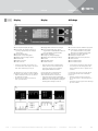
Display
A1 Select input and display info page
A2 Reset button: The module can be reset
byusing a pointed object (for example,
apaper clip).
A3 Select measured values
A4 Display the corresponding input
A5 Attribute (current, voltage, output)
A6 Measured value
A7 Network connection
A8 Serial connection
• If a PDU has more than one input cable, you
can switch between the displays for the various
input cables (modules) by pressing A1.
The alignment of the LCD screen and the display
background can be adjusted to improve readability.
• Hold the A3 button for about one second until
the display has turned 90°.
• Repeat the process above until the display
meets your requirements.
Operation
Affichage
A1 Sélectionner l’entrée et afficher la page Info
A2 Touche Reset: À l’aide d’un objet pointu
(p.ex. attache trombone), vous pouvez
déclencher un redémarrage du module.
A3 Sélectionner les valeurs de mesure
A4 Affichage de chaque entrée
A5 Attribut (intensité, tension, puissance)
A6 Valeur mesurée
A7 Raccordement réseau
A8 Raccordement réseau
• Si le PDU dispose de plusieurs câbles d’entrée,
vous pouvez passer de l’affichage d’un câble
d’entrée (modules) à l’autre en appuyant sur la
toucheA1.
L'orientation de l’écranLCD et des fonds d’écran
peut être réglée afin de faciliter la lisibilité de
l’écranLCD.
• Maintenez la toucheA3 enfoncée (environ
uneseconde) jusqu’à ce que l’affichage pivote
de 90°.
• Renouvelez l’opération jusqu’à obtenir l’affichage
que vous souhaitez.
Exploitation

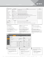
Display in web browser
Once the connection has been established (see 4.1),
the web browser displays the “Summary” page with
the measured values.
B1 PDU input
B2 Phase values
B3 Phase
B4 Status symbol
B5 Bar graph display
B6 Current reading
B7 Voltage reading
B8 Effective power
B9 Apparent power
B10 Energy
B11 Power factor
Note
If the “out of balance” alarm is issued,
there is a danger of overheating for the
PDU and the connected equipment. This
can cause serious damage to the equip-
ment, the PDU and the housing.
• If this happens, the PDU must be
switched off.
Note
If the input voltage of the PDU is below
the alarm level, the connected equipment
and the PDU could suffer damage.
• If this is the case, the load must be
immediately adapted so that the alarm
stops.
12Vertiv | Vertiv Knürr DIS Load Meter Module with Remote Monitoring – Power Distribution Units | 03.300.999.8 I ECR. No. 18618 I 10/18
Anzeige im Web-Browser
Wenn die Verbindung aufgebaut ist (siehe 4.1), zeigt
der Web-Browser die „Summary“ Seite mit den
Messwerten an.
B1 PDU Input
B2 Phasenwerte
B3 Phase
B4 Statussymbol
B5 Bargraph-Anzeige
B6 Strom-Messwert
B7 Spannungs-Messwert
B8 Wirkleistung
B9 Scheinleistung
B10 Energieg
B11 Leistungsfaktor
Hinweis
Falls die Eingangsspannung der PDU
unter dem Alarmniveau liegt, könnten die
angeschlossene Ausrüstung und die PDU
Schaden nehmen.
• In diesem Fall muss die Last umgehend
angepasst werden, damit der Alarm
wieder gelöscht wird.
E
Betrieb
Operation Exploitation
Affichage dans le navigateur Internet
Lorsque la connexion est établie (voir 4.1), le
navigateur Internet affiche la page «Summary»
(Sommaire) avec les valeurs de mesure.
B1 Entrée PDU
B2 Valeurs de phase
B3 Phase
B4 Symbole de statut
B5 Graphique en barre
B6 Valeur mesurée d’intensité
B7 Valeur mesurée de tension
B8 Puissance réelle
B9 Puissance apparente
B10 Énergie
B11 Coefficient de puissance
Remarque
Si la tension d’entrée du PDU est
inférieure au niveau d’alarme, l’équipement
raccordé et le PDU pourraient être
endommagés.
• Dans ce cas, la charge doit immédia-
tement être adaptée pour que l’alarme
s’éteigne.
Hinweis
Gefahr einer Überhitzung für die PDU und
die angeschlossene Ausrüstung falls der
Alarm „out of balance” ansteht. Dies kann
zu schweren Schäden an der Ausrüstung,
der PDU und dem Gehäuse führen.
• In diesem Fall muss die PDU
abgeschaltet werden.
Remarque
Risque de surchauffe du PDU et des
équipements raccordés en cas d’alarme
«out of balance» (déséquilibre). Cela peut
entraîner de graves dommages au niveau
de l’équipement, du PDU et du boîtier.
• Dans ce cas, le PDU doit être éteint..

13Vertiv | Vertiv Knürr DIS Load Meter Module with Remote Monitoring – Power Distribution Units | 03.300.999.8 I ECR. No. 18618 I 10/18
Farben auf der Anzeige
Colors on the display
Couleurs de l’affichage
Betrieb
Operation Exploitation

F
G
14Vertiv | Vertiv Knürr DIS Load Meter Module with Remote Monitoring – Power Distribution Units | 03.300.999.8 I ECR. No. 18618 I 10/18
Einstellung
Bezeichnung und Standort der PDU
Der PDU kann eine Systembezeichnung, eine
Beschreibung, eine Kontaktbezeichnung und ein
Standort zugeordnet werden, um es einfacher zu
identifizieren.
Alle diese Kennzeichnungen werden danach
inder Kopfzeile einer jeden Seite im Web-Browser
angezeigt.
• Vergewissern Sie sich, dass Sie über das Netzwerk auf
die PDU zugreifen können (siehe 4.1).
• Klicken Sie auf „Systems”.
• Melden Sie sich als Administrator an.
• Wählen Sie „PDU Information“ an.
• Geben Sie die Bezeichnung und den Standort
der PDU ein. Die Kennzeichnungen mit
Bezeichnung und Standort dürfen nicht mehr als
15 Zeichen aufweisen.
• Klicken Sie auf „Submit“, um die Eingaben zu
speichern.
• Laden Sie die Webseite neu damit die
Einstellungen angezeigt werden.
Einstellen oder Ändern von Benutzername
und Passwort
• Vergewissern Sie sich, dass Sie über das Netzwerk auf
die PDU zugreifen können (siehe 4.1).
• Klicken Sie auf „Systems”.
• Melden Sie sich als Administrator an.
• Wählen Sie Registerkarte HTTP Access an
• Geben Sie die Namen und Passwörter für
höchstens fünf User/Administratoren ein.
Die Namen und Passwörter dürfen nur
Buchstaben und Ziffern enthalten.
• Legen Sie die User- oder Administrator-
Zugriffsrechte für jeden User fest.
• Klicken Sie auf „Submit“, um die Eingaben zu
speichern.
4.4
Betrieb
Operation Exploitation
Setting
Name and location of the PDU
The PDU can be assigned a system identifier, a
description, a contact identifier, and a location in
order to more easily identify it.
All of these designations are then shown in the
header of every page in the web browser.
• Make sure that you have access to the PDU over
the network (see 4.1).
• Click on “Systems”.
• Log in as an administrator.
• Select “PDU Information”.
• Enter the name and location of the PDU.
Thedesignations with description and location
may not exceed 15 characters.
• Click on “Submit” to save the entries.
• Reload the website so that the settings are
displayed.
Setting or changing the username and
password
• Make sure that you have access to the PDU over
the network (see 4.1).
• Click on “Systems”.
• Log in as an administrator.
• Select the tab “HTTP Access”.
• Enter the names and passwords for no more
than five users/administrators.
The names and passwords may be comprised
only of letters and numbers.
• Determine the access rights for each user and
administrator.
• Click on “Submit” to save the entries.
Réglage
Désignation et site du PDU
Une désignation de système, une description,
une désignation de contact ou encore un site
peuvent être attribués au PDU pour l’identifier plus
facilement.
Toutes ces identifications sont ensuite affichées
dans la ligne de tête de chaque page du navigateur
Internet.
• Assurez-vous d’avoir accès au PDU via le réseau
(voir 4.1).
• Cliquez sur «Systems» (Systèmes).
• Connectez-vous en tant qu’administrateur.
• Sélectionnez «PDU Information» (Informations
PDU).
• Saisissez l’identification et le site du PDU. Les
identifications et site ne doivent pas comporter
plus de 15caractères.
• Cliquez sur «Submit» (Valider) pour enregistrer
les données.
• Rechargez la page web pour que les réglages
soient affichés.
Réglage ou modification du nom
d’utilisateur et du mot de passe
• Assurez-vous d’avoir accès au PDU via le réseau
(voir 4.1).
• Cliquez sur «Systems» (Systèmes).
• Connectez-vous en tant qu’administrateur.
• Sélectionnez l’onglet HTTP Access
• Saisissez les noms et mots de passe pour un
maximum de cinq utilisateurs ou administrateurs.
Les noms et mots de passe ne doivent
comporter que des lettres et des chiffres.
• Déterminez les droits d’accès utilisateur ou
administrateur pour chaque utilisateur.
• Cliquez sur «Submit» (Valider) pour enregistrer
les données.

H
15Vertiv | Vertiv Knürr DIS Load Meter Module with Remote Monitoring – Power Distribution Units | 03.300.999.8 I ECR. No. 18618 I 10/18
Aktivieren der System Log Nachrichten
Die PDU kann konfiguriert werden, um kritische
Systemereignisse und Konfigurationsänderungen
zu überwachen, sodass System Log Nachrichten
(
syslog
) in Ihre Systeme im Netzwerk hochge-
schickt werden.
Beispiel für eine System Log Nachricht:
• Vergewissern Sie sich, dass Sie über das
Netzwerk auf die PDU zugreifen können (siehe
4.1).
• Klicken Sie auf „Systems”.
• Melden Sie sich als Administrator an.
• Wählen Sie die Registerkarte „Syslog“ an
• Geben Sie bis zu vier IP Adressen ein und
klicken Sie das Aktivierungskästchen neben der
IP Adresse der Systeme an, von denen Sie möch-
ten, dass die Messeinheit
syslog
Nachrichten
sendet
• Klicken Sie auf „Submit“, um die Eingaben zu
speichern.
• Stellen Sie die Zeitdauer zwischen dem Senden
der
syslog
Nachrichten ein
Zulässige Zeiteinstellwerte:
Stunden: 0 - 23
Minuten: 0 - 59
Sekunden: 0 - 59
• Klicken Sie das Alarm Kontrollkästchen an, um
das Senden von Alarmnachrichten über
syslog
Nachrichten zu ermöglichen.
• Mit Alarmeinstellungen aktiviert, und wenn die
Grenzwertparameter eingestellt sind, sendet die
Messeinheit Nachrichten über
syslog
sobald die
Grenzwerte erreicht werden
• Klicken Sie auf „Submit“, um die Eingaben zu
speichern.
• Wählen Sie die überwachten Werte aus, diean
die
syslog
Systeme zu senden sind.
• Klicken Sie auf „Submit“, um die Eingaben zu
speichern.
Betrieb
Operation Exploitation
Activating system log messages
The PDU can be configured to monitor critical
system events and configuration changes, so that
system log messages (
syslog
) are sent to your
systems in the network.
Example of a system log message:
• Make sure that you have access to the PDU over
the network (see 4.1).
• Click on “Systems”.
• Log in as an administrator.
• Select the tab “Syslog”.
• Enter up to four IP addresses and click on the
activation checkbox next to the system IP
addresses for those from which you want the
meter unit to send
syslog
messages.
• Click on “Submit” to save the entries.
• Set the duration between sending the
syslog
messages.
Permissible time settings:
Hours: 0 - 23
minutes: 0 - 59
seconds: 0 - 59
• Click on the alarm checkbox to enable sending
alarm messages via
syslog
messages.
• With alarm settings activated, and if the limit
value parameters are set, the meter unit sends
messages via
syslog
as soon as the limit values
are reached.
• Click on “Submit” to save the entries.
• Select the monitored values to be sent to the
syslog
systems.
• Click on “Submit” to save the entries.
Activation des messages d’enregistrement
système
Le PDU peut être configuré pour surveiller des
événements système et des modifications de
configuration critiques, de sorte que des messages
d’enregistrement système (
syslog
) soient envoyés
dans votre réseau.
Exemple de message d’enregistrement système:
• Assurez-vous d’avoir accès au PDU via le réseau
(voir 4.1).
• Cliquez sur «Systems» (Systèmes).
• Connectez-vous en tant qu’administrateur.
• Sélectionnez l’onglet «Syslog»
• Saisissez jusqu’à quatre adressesIP et cochez
la case d’activation située à côté de l’adresseIP
des systèmes dont vous souhaité que l’unité de
mesure envoie des messages
syslog
• Cliquez sur «Submit» (Valider) pour enregistrer
les données.
• Réglez la durée séparant les envois de messages
syslog
Seuils autorisés:
Heures: 0 - 23
Minutes: 0 - 59
Secondes: 0 - 59
• Cliquez sur la case de l’alarme pour autoriser
l’envoi de messages d’alarme
syslog
.
• Lorsque les réglages de l’alarme sont activés et
que les paramètres de seuils sont réglés, l’unité
de mesure envoie des messages
syslog
dès que
les seuils sont atteints
• Cliquez sur «Submit» (Valider) pour enregistrer
les données.
• Sélectionnez les valeurs contrôlées à en voyer
aux systèmes
syslog
.
• Cliquez sur «Submit» (Valider) pour enregistrer
les données.

16Vertiv | Vertiv Knürr DIS Load Meter Module with Remote Monitoring – Power Distribution Units | 03.300.999.8 I ECR. No. 18618 I 10/18
I
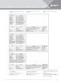
SNMP
Falls das SNMP (Simple Network Management
Protocol) aktiv ist, können Nachrichten von der PDU
an SNMP Agenten im Netzwerk gesendet und von
diesen empfangen werden.
• Die folgende Tabelle beschreibt unterstützte
SNMP-Traps, die die PDU Messeinheit an die
SNMP Agenten im Netzwerk senden kann
4.5
BetriebOperation Exploitation
SNMP
If SNMP (Simple Network Management Protocol)
is active, messages can be sent from the PDU to
SNMP agents in the network and received by them.
• The following table describes supported SNMP
traps that the PDU meter unit can send to the
SNMP agents in the network.
SNMP
Si SNMP (Simple Network Management Protocol) est
actif, des messages peuvent être envoyés du PDU
aux agents SNMP. Ces derniers peuvent les recevoir.
• Le tableau ci-dessous décrit les déroute-
mentsSNMP que l’unité de mesure PDU peut
envoyer aux agentsSNMP
I

17Vertiv | Vertiv Knürr DIS Load Meter Module with Remote Monitoring – Power Distribution Units | 03.300.999.8 I ECR. No. 18618 I 10/18
• Vergewissern Sie sich, dass Sie über das
Netzwerk auf die PDU zugreifen können
(siehe4.1).
• Klicken Sie auf „Systems”.
• Melden Sie sich als Administrator an.
• Wählen Sie die Registerkarte „SNMP Access“ an.
• Aktivieren Sie SNMP v1/v2 oder SNMP v3.
• Stellen Sie bis zu vier NMS (Network Management
Host) im Netzwerk für SNMP v1/v2 ein.
• Stellen Sie bis zu 10 Network Management Hosts
im Netzwerk für SNMP v3 ein.
• Klicken Sie auf „Submit“, um die Eingaben zu
speichern.
Warnung
Falls das „HTTP enable“ Kontrollkästchen
nicht angekreuzt ist, ist kein Zugriff auf
die HTML Schnittstelle mit einem
Web-Browser möglich.
• In einem solchen Fall aktivieren Sie den
HTTP Zugriff mithilfe der SNMP Agent
Software.
• Siehe in der Dokumentation für den
SNMP Agent.
BetriebOperation Exploitation
I
• Make sure that you have access to the PDU over
the network (see 4.1).
• Click on “Systems”.
• Log in as an administrator.
• Select the tab “SNMP Access”.
• Activate SNMP v1/v2 or SNMP v3.
• Set up to four NMS (network management host) in
the network for SNMP v1/v2.
• Set up to 10 network management hosts in the
network for SNMP v3.
• Click on “Submit” to save the entries.
Warning
If the “HTTP enable” checkbox is not
checked, it is not possible to access the
HTML interface with a web browser.
• If this is the case, activate HTTP
access using SNMP agent software.
• Refer to the documentation for the
SNMP agent.
• Assurez-vous d’avoir accès au PDU via le réseau
(voir 4.1).
• Cliquez sur «Systems» (Systèmes).
• Connectez-vous en tant qu’administrateur.
• Sélectionnez l’onglet «SNMP Access» (Accès
SNMP)
• Activez SNMP v1/v2 ou SNMP v3.
• Paramétrez jusqu’à quatre NMS (Network
Management Host) dans le réseau pour SNMP v1/v2.
• Paramétrez jusqu’à dix NMS (Network
Management Host) dans le réseau pour SNMP v3.
• Cliquez sur «Submit» (Valider) pour enregistrer
les données.
Alerte
Si la case «HTTP enable» (HTTP
autorisé) n’est pas cochée, aucun accès
à l’interfaceHTML n’est possible via un
navigateur Internet.
• Dans un tel cas, activez l’accès HTTP
à l’aide du logiciel SNMP Agent.
• Référez-vous à la documentation
relative à SNMP Agent.
J

18Vertiv | Vertiv Knürr DIS Load Meter Module with Remote Monitoring – Power Distribution Units | 03.300.999.8 I ECR. No. 18618 I 10/18
Einstellen der SNMP Traps
• Vergewissern Sie sich, dass Sie über das Netzwerk auf
die PDU zugreifen können (siehe 4.1).
• Klicken Sie auf „Systems”.
• Melden Sie sich als Administrator an.
• Wählen Sie die Registerkarte „SNMP Traps“ an
• Stellen Sie bis zu 10 SNMP-Trap Hosts ein
• Wählen Sie die SNMP-Trap Version an und kreuzen
Sie das Aktivieren-Kontrollkästchen für Traps an,
die an den ausgewählten Host zusenden sind.
• Klicken Sie auf „Submit“, um die Eingaben zu
speichern.
• Stellen Sie die Werte für die wiederholten Trap
Einstellungen ein (die Beschreibung befindet
sich in der Tabelle Pic. I)
• Klicken Sie auf „Submit“, um die Eingaben zu
speichern.
• Senden Sie ein Test-Trap zur Überprüfung der
SNMP Einstellungen
Zugriff auf die Ereignisproto -
kollierungsseite
Die Ereignisprotokollierungsseite ist eine Schnittstelle,
inklusive Löschoptionen, die es ermöglicht, die letzten
1 000 Ereignisse (20Ereignisse je Seite, max 50 Seiten)
erneut einzusehen.
• Vergewissern Sie sich, dass Sie über das Netzwerk
auf die PDU zugreifen können (siehe 4.1).
• Klicken Sie auf „Systems”.
• Melden Sie sich als Administrator an.
• Wählen Sie die Registerkarte „Event Logging“ an.
• Bei Bedarf steht eine Option zum Löschen der
Ereignisliste zur Verfügung.
L
4.6
K
K
Setting the SNMP traps
• Make sure that you have access to the PDU over
the network (see 4.1).
• Click on “Systems”.
• Log in as an administrator.
• Select the tab “SNMP Traps”.
• Set up to 10 SNMP trap hosts.
• Select the SNMP trap version and check the
activation checkbox for traps to be sent to the
selected host.
• Click on “Submit” to save the entries.
• Set the values for the repeating trap settings
(the description is in the table Pic. I).
• Click on “Submit” to save the entries.
• Send a test trap to check the SNMP settings.
Access to the event logging
page
The event logging page is an interface, including de-
letion options, that enable the last 1,000 events (20
events per page, max. 50 pages) to be viewed again.
• Make sure that you have access to the PDU over
the network (see 4.1).
• Click on “Systems”.
• Log in as an administrator.
Select the tab “Event Logging”.
• There is an option available to clear the event list.
BetriebOperation Exploitation
Réglage des déroutementsSNMP
• Assurez-vous d’avoir accès au PDU via le réseau
(voir 4.1).
• Cliquez sur «Systems» (Systèmes).
• Connectez-vous en tant qu’administrateur.
• Sélectionnez l’onglet «SNMP Traps»
(DéroutementsSNMP)
• Paramétrez jusqu’à dix SNMP Trap Hosts (hôtes
de déroutement SNMP)
• Sélectionnez la version de déroutement SNMP et
cochez la case d’activation pour les déroutements
à envoyer aux hôtes sélectionnés.
• Cliquez sur «Submit» (Valider) pour enregistrer
les données.
• Paramétrez les valeurs pour les réglages de
déroutements répétés (vous trouverez leur
description dans le tableau Fig. I)
• Cliquez sur «Submit» (Valider) pour enregistrer
les données.
• Envoyez un déroutement-test pour contrôler les
réglagesSNMP
Accès à la page d’enregistre-
ment des événements
La page d’enregistrement des événements est une
interface comportant des options de suppressions. Elle
permet de visualiser les 1000derniers événements
(20événements par page, 50pages maximum).
• Assurez-vous d’avoir accès au PDU via le réseau
(voir 4.1).
• Cliquez sur «Systems» (Systèmes).
• Connectez-vous en tant qu’administrateur.
• Sélectionnez l’onglet «Event Logging»
(Enregistrement des événements)
• En cas de besoin, une option de suppression de
la liste d’événements est disponible.

K
19Vertiv | Vertiv Knürr DIS Load Meter Module with Remote Monitoring – Power Distribution Units | 03.300.999.8 I ECR. No. 18618 I 10/18
Einstellen der Systemzeit
• Vergewissern Sie sich, dass Sie über das
Netzwerk auf die PDU zugreifen können
(siehe4.1).
• Klicken Sie auf „Systems”.
• Melden Sie sich als Administrator an.
• Wählen Sie die Registerkarte „System Time“ an.
• Bei einer manuellen Einstellung geben Sie die
aktuelle Zeit und das aktuelle Datum ein.
• Klicken Sie auf „Submit“, um die Eingaben zu
speichern.
• Bei NTP-Server Einstellungen kreuzen Sie das
Kontrollkästchen für Aktivieren an.
• Geben Sie die NTP-Server Referenzen ein.
• Klicken Sie auf „Submit“, um die Eingaben zu
speichern.
• Bei Bedarf aktivieren Sie für Ihren Standort die
DST Einstellungen (Daylight Saving Time).
Einstellung des CLI Zugriffs
• Vergewissern Sie sich, dass Sie über das
Netzwerk auf die PDU zugreifen können
(siehe4.1).
• Klicken Sie auf „Systems”.
• Melden Sie sich als Administrator an.
• Wählen Sie die Registerkarte „CLI Access“ an.
• Wählen Sie SSH, Telnet oder die Option zum
Abwählen.
• Klicken Sie auf „Submit“, um die Eingaben zu
speichern.
•
•
•
• Nach einer erfolgreichen Anmeldung können Sie
verschiedene Befehle im CLI Bild verwenden
• Der Eintrag der Syntax
help
in die Befehlszeile
stellt eine Liste mit unterstützten Themen zur
Verfügung. Die Liste mit den abgedeckten
Themen kann je nach Ausgabe der Firmware
anders sein.
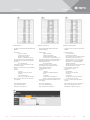
• Einen Überblick über die unterstützten Themen
finden Sie in der Tabelle M.
N
4.7
4.8
M
BetriebOperation Exploitation
Setting the system time
• Make sure that you have access to the PDU over
the network (see 4.1).
• Click on “Systems”.
• Log in as an administrator.
• Select the tab “System Time”.
• To set manually, enter the current time and date.
• Click on “Submit” to save the entries.
• For NTP server settings, check the activation
checkbox.
• Enter the NTP server references.
• Click on “Submit” to save the entries.
• If required, activate the DST settings for your
location (Daylight Saving Time).
Setting CLI access
• Make sure that you have access to the PDU over
the network (see 4.1).
• Click on “Systems”.
• Log in as an administrator.
• Select the tab “CLI Access”.
• Select SSH, Telnet, or the option to deselect.
• Click on “Submit” to save the entries.
• After successfully logging in, you can use vari-
ous commands in the CLI image.
• Entering the syntax
help
in the command line
presents a list with supported topics. The list
ofcovered topics can be different depending on
the firmware version.
• An overview of supported topics can be found
in Table M.
Réglage de l’heure du système
• Assurez-vous d’avoir accès au PDU via le réseau
(voir 4.1).
• Cliquez sur «Systems» (Systèmes).
• Connectez-vous en tant qu’administrateur.
• Sélectionnez l’onglet «System Time» (heure du
système)
• Lors d’une réglage manuel, saisissez l’heure et la
date actuelles.
• Cliquez sur «Submit» (Valider) pour enregistrer
les données.
• Pour le réglage d’un serveurNTP, cochez la case
d’activation.
• Saisissez les références du serveurNTP.
• Cliquez sur «Submit» (Valider) pour enregistrer
les données.
• En cas de besoin, activez les réglagesDST
(Daylight Saving Time) pour votre site.
Réglage de l’accès CLI
• Assurez-vous d’avoir accès au PDU via le réseau
(voir 4.1).
• Cliquez sur «Systems» (Systèmes).
• Connectez-vous en tant qu’administrateur.
• Sélectionnez l’onglet «CLI Access» (Accès CLI)
• Sélectionnez SSH, Telnet ou l’option à décocher.
• Cliquez sur «Submit» (Valider) pour enregistrer
les données.
• Après votre connexion, vous pouvez utiliser les
divers ordres de l’image CLI
• La saisie de la commande
help
dans la ligne
de commande met à disposition une liste
comportant les sujets autorisés. La liste des
sujets couverts peut être différente selon la
version du firmware.
• Le tableauM fournit un aperçu des sujets
autorisés.

• Overview of the topics included under the
help
command
O
• Aperçu des sujets saisis pour la commande
d’aide
• Pour une liste comportant des ordres valables
pour une ligne de commande d’informations liée
aux sujets:
pducli -> help
topic-name
• Pour une aide pour une ligne de commande
d’information particulière liée à une commande:
pducli -> help
command-name
• For a list of valid commands for a topic-related
info command line:
pducli -> help
topic-name
• For help or a special command-related info
command line:
pducli -> help
command-name
20Vertiv | Vertiv Knürr DIS Load Meter Module with Remote Monitoring – Power Distribution Units | 03.300.999.8 I ECR. No. 18618 I 10/18
O
• Überblick über die erfassten Themen für den
Hilfe
-Befehl
• Für eine Liste mit gültigen Befehlen für eine
themenbezogene Info-Befehlszeile:
pducli -> help
topic-name
• Für Hilfe für eine spezielle befehlsbezogene
Info-Befehlszeile:
pducli -> help
command-name
O
BetriebOperation Exploitation
Page is loading ...
Page is loading ...
Page is loading ...
Page is loading ...
Page is loading ...
Page is loading ...
Page is loading ...
Page is loading ...
Page is loading ...
-
 1
1
-
 2
2
-
 3
3
-
 4
4
-
 5
5
-
 6
6
-
 7
7
-
 8
8
-
 9
9
-
 10
10
-
 11
11
-
 12
12
-
 13
13
-
 14
14
-
 15
15
-
 16
16
-
 17
17
-
 18
18
-
 19
19
-
 20
20
-
 21
21
-
 22
22
-
 23
23
-
 24
24
-
 25
25
-
 26
26
-
 27
27
-
 28
28
-
 29
29


Vertiv Knurr DIS - I User manual
- Category
- Power distribution units (PDUs)
- Type
- User manual
- This manual is also suitable for
Ask a question and I''ll find the answer in the document
Finding information in a document is now easier with AI
in other languages
- français: Vertiv Knurr DIS - I Manuel utilisateur
- Deutsch: Vertiv Knurr DIS - I Benutzerhandbuch
Related papers
-
Vertiv MPX - Inline Metering System User manual
-
-
-
-
-
-
-
-
-