Hearth and Home Technologies DRC-RADIUS User manual
- Type
- User manual

Hearth & Home Technologies Inc. • Cinch Pipe & Term Caps • 4033-900 Rev K • 05/05
1
TM
TM
Models:
Cinch Pipe & Termination Cap System
Installation
Instructions
If you need assistance during installation, contact your local dealer or the Technical Serices Dept., Hearth & Home Technologies
Inc., phone 1-800-927-6841 or 1-888-427-3973.
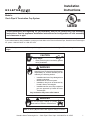
Note: An arrow () found in the text signifi es change in content.
Sharp Edges
• Wear protective gloves and safety glasses
during installation.
CAUTION
These instructions are replacing VP (for Heatilator) and DV (for Heat-N-Glo) pipe assembly
instructions. See the appliance installation instructions for confi guration of vent assembly
and clearances to pipe.
If DVP-AD adapters are used off the top of the appliance, the termination height will be raised by 2-3/4 in. overall
height.
Hearth & Home Technologies disclaims any
responsibility for, and the warranty will be
voided by, the following actions:
• Installation and use of any damaged vent
system component.
• Modifi catoin of the vent system.
• Installation other than as instructed by
Hearth & Home Technologies.
• Installation and/or use of any component
part not approved by Hearth & Home
Technologies.
Any such action may cause a fi re hazard.
WARNING
Do not mix pipe, fittings or joining
methods from different manufacturers.
WARNING

Hearth & Home Technologies Inc. • Cinch Pipe & Term Caps • 4033-900 Rev K • 05/05
2
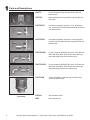
DVP-TV Vertical termination cap. Includes storm collar and
fastener pack.
DVP-TB1 Basement/window well termination cap. Includes fas-
tener pack.
DVP-TRAP2 Horizontal termination cap with 4 in. telescoping fl ue.
Includes DVP-WS wall shield with heat shield and one
fastener pack.
DVP-TRAPK1 Vent kit containing DVP90ST 90° elbow, DVP-WS wall
shield with heat shield, DVP-TRAP1 termination cap
with telescoping fl ue and one fastener pack.
DVP-TRAPK2 Vent kit containing DVP90ST 90° elbow, DVP-WS wall
shield with heat shield, DVP-TRAP2 termination cap
with telescoping fl ue and one fastener pack.
DVP-TRAP1 Horizontal termination cap with 1-3/4 in. telescoping
fl ue. Includes DVP-WS wall shield with heat shield and
one fastener pack.
DVP- TVHW Vertical Termination, high wind cap. Includes storm
collar and fastener pack.
DVP-AS Attic insulation shield
BEK Brick extension kit
(not shown)
1
1
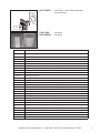
Parts and Descriptions

Hearth & Home Technologies Inc. • Cinch Pipe & Term Caps • 4033-900 Rev K • 05/05
3
COOL ADD Cap shield
DRC-RADIUS Cap shield
DVP-TRAPFL DVP-TRAP1 or DVP-TRAP2 termination
cap rain fl ashing
DVP-TRAP1
DVP-TRAP2
Termination Cap
DVP-TRAPFL
Flashing
Components Description
DRC-RADIUS Cap Shield
COOL-ADDM Cap Shield - pack of six
DVP-TV Vertical Termination Cap
DVP45 45° Elbow
DVP90ST 90° Elbow
RF6M Roof Flashing (vertical termination for 0/12 to 6/12 pitch) - pack of four
RF12M Steep Pitch Roof Flashing (for 7/12 to 12/12 pitch) - pack of six
DVP4 4 in. length Vent Pipe
DVP6 6 in. length Vent Pipe
DVP12 12 in. length Vent Pipe
DVP24 24 in. length Vent Pipe
DVP36 36 in. length Vent Pipe
DVP48 48 in. length Vent Pipe
DVP6A 3 in. - 6 in. Slip Section Vent Pipe (to be used with another piece of pipe)
DVP12A 3 in. - 12 in. Slip Section Vent Pipe (to be used with another piece of pipe)
DVP12MI 12 in. Vent Pipe - non-unitized (can be cut to length)
DVP24MI 24 in. Vent Pipe - non-unitized (can be cut to length)
DVP-HVS Vent Support
DVP-WS Wall Shield to ensure horizontal clearances
DVP-FS Firestop Spacer
DVP-TRAP1 Horizontal Termination Cap with 1-3/4 in. telescoping fl ue and wall shield with heat shield
DVP-TRAP2 Horizontal Termination Cap with 4 in. telescoping fl ue and wall shield with heat shield
DVP-TB1 Basement Horizontal Termination Cap
DVP-TRAPK1 Top Vent Horizontal Kit with DVP-TRAP1 Termination Cap, wall shield with heat shield, and 90° elbow
DVP-TRAPK2 Top Vent Horizontal Kit with DVP-TRAP2 Termination Cap, wall shield with heat shield, and 90° elbow
DVP-HSM Extended Heat Shield
BEK Brick Extension Kit
DVP-AS Attic Insulation Shield

Hearth & Home Technologies Inc. • Cinch Pipe & Term Caps • 4033-900 Rev K • 05/05
4
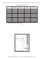
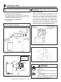
Vent depth is measured from the back of the appliance to the outer edge of the exterior wall. See Table 1 and Figure 1.
Figure 1 - Measuring Required Vent Depth
Table 1
TRAP CAP SPECIFICATION CHART
Appliance
DVP-TRAPK1
Top Vent
Depth
DVP-TRAP1
Rear Vent
Depth
DVP-TRAPK2
Top Vent
Depth
DVP-TRAP2
Rear Vent
Depth
Novus 4-1/2 in. to 6-1/4 in. 3-1/2 in. to 4-3/4 in. 7 in. to 11 in. 5-1/2 in. to 9-1/2 in.
NXT 4-1/8 in. to 5-7/8 in. 4-5/8 in. to 6-3/8 in. 6-1/2 in. to 10-1/2 in. 7-1/4 in. to 11-1/4 in.
Caliber 4-1/8 in. to 5-7/8 in. 3-5/8 in. to 5-3/8 in. 6-1/2 in. to 10-1/2 in. 6-1/4 in. to 10-1/4 in.
Maxus 4-1/2 in. to 6-1/4 in. 4-1/8 in. to 5-7/8 in. 6-7/8 in. to 10-7/8 in. 6-3/4 in. to 10-3/4 in.
GNTC50 5 in. to 6-3/4 in. 4-7/8 in. to 6-5/8 in. 7-3/8 in. to 11-3/8 in. 7-3/8 in. to 11-3/8 in.
Designer* 4 in. to 5-3/4 in. 5-3/4 in. to 7-1/2 in. 6-3/8 in. to 10-3/8 in. 8-1/8 in. to 12-1/8 in.
Titan 3-1/2 in. to 5-1/4 in. N/A 6 in. to 10 in. N/A
6000 2-3/4 in. to 4-1/2 in. 3-1/8 in. to 4-7/8 in. 5-1/4 in. to 9-1/4 in. 5-5/8 in. to 9-5/8 in.
8000 2-3/4 in. to 4-1/2 in. 3-1/8 in. to 4-7/8 in. 5-1/4 in. to 9-1/4 in. 5-5/8 in. to 9-5/8 in.
Olympian 3-1/2 in. to 5-1/4 in. N/A 6 in. to 10 in. N/A
Multisided 7-1/2 in. to 9-1/4 in. 3-1/8 in. to 4-7/8 in. 10 in. to 14 in. 5-5/8 in. to 9-5/8 in.
Gem 4-1/2 in. to 6-1/4 in. N/A 7 in. to 11 in. N/A
SL units N/A 3-1/8 in. to 4-7/8 in. N/A 5-5/8 in. to 9-5/8 in.
ICON 3-1/2 in. to 5-1/4 in. N/A 6-1/2 in. to 10-1/2 in. N/A
GDST5244I** 4 in. to 5-3/4 in. N/A 6-3/4 in. to 7-3/4 in. N/A
* Top vented appliance - Designer needs a DVP12 after the elbow.
** GDST5244I requires a DVP12 and DVP6 after the elbow.

Hearth & Home Technologies Inc. • Cinch Pipe & Term Caps • 4033-900 Rev K • 05/05
5
3 in. (76 mm)
top clearance
1 in. (25 mm)
clearance
bottom & sides
Heat
Shield
Wall
Shield
Heat
Shield
WALL
Note: Heat shields
MUST overlap by a
minimum of
1-1/2 in. (38 mm).
Figure 2.2 Horizontal Venting Clearances to Combustible Materi-
als - Rear Vent
A. Clearances for the Vent Sections
• Top Vented Direct Vent Appliances
For all top vented, direct vent appliances, clearances to
combustible materials from the venting system need to
be maintained as shown in Figure 2.1.
• Rear Vented Direct Vent Appliances
See Figure 2.2.
Figure 2.1 Horizontal Venting Clearances to Combustible Materi-
als - Top Vent
Note: For termination cap installations only, go directly to Sec-
tion E.
Note: Refer to the appliance installation instructions for al-
lowed vent lengths and confi gurations.
2
Installing Vent Pipe
B. Penetrating a Wall
Wherever a combustible wall is penetrated, the hole must
be framed with an interior wall shield (DVP-WS) as shown in
Figures 2.3-2.4. This shield maintains minimum clearances
and restricts cold air infi ltration. If the wall being penetrated is
of noncombustible materials (material which will not ignite or
burn, or has a UL fi re rating of zero), a 9 in. diameter hole is
acceptable. Whenever a wall is penetrated the wall shield is only
required on one side and no heat shield is necessary. If your
local inspector requires the wall shield on both sides, then both
wall shields must have a heat shield attached to them.
Figure 2.4 Interior Wall Shield
Figure 2.3 Exterior Wall Hole
Note: Heat shields MUST overlap by 1-1/2 in. min. for rear
vented appliances.
Fire Risk
Explosion Risk
Maintain vent clearance to combustibles as
specifi ed.
• Do not pack air space with insulation or
other materials.
Failure to keep insulation or other materials
away from vent pipe may cause fi re.
WARNING

Hearth & Home Technologies Inc. • Cinch Pipe & Term Caps • 4033-900 Rev K • 05/05
6
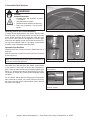
C. Assemble Vent Sections
Figure 2.5 Lances
A
B
Figure 2.6 Inner/Outer
A
B
Figure 2.7 Snapped
CORRECT INCORRECT
Make sure the seams are not aligned to prevent unintentional
disconnection.
Figure 2.8 Seams
Fire Risk
Exhaust Fumes Risk
• Overlap pipe slip sections at least
1-1/2 inches.
• Use pilot holes for screws.
• Screws must not exceed one inch long.
• Pipe may separate if not properly
joined.
WARNING
Attaching Vent to the Firebox Assembly
To attach the fi rst pipe section to the collars, slide the male
end of the inner vent of the pipe section over the inner collar
on the fi rebox assembly. At the same time, slide the outer
fl ue over the outer collar on the appliance. Push the pipe
section into the appliance collar until all the lances (see Fig-
ure 2.5) have snapped in place. Tug slightly on the section
to confi rm it has completely locked into place.
Assemble Pipe Sections
Insert the inner fl ue of section A into the fl ared inner fl ue of
section B.
Start the outer fl ue of section A over the outer fl ue of section
B (see Figure 2.6).
Note: The end of the pipe sections with the lances/tabs on
it will face towards the appliance.
Once both inner and outer fl ues are started, press section
A onto section B fi rmly until all lances have snapped into
place. Check to make sure they have snapped together (see
Figure 2.7) and the seams are not aligned (see Figure 2.8).
Tug slightly on section A to confi rm it has completely locked
into place.
For 90° and 45° elbows that are changing the vent direction
from horizontal to vertical, one screw minimum should be
put in the outer fl ue at the horizontal elbow joint to prevent
the elbow from rotating.

Hearth & Home Technologies Inc. • Cinch Pipe & Term Caps • 4033-900 Rev K • 05/05
7
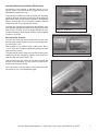
Assemble Minimum Installation (MI) Sections
MI sections are non-unitized so that they can be cut to a
specifi c length. Cut these sections to length from the non-
expanded end (see Figure 2.9).
They can then be attached by fi rst connecting the expanded
end of the MI inner fl ue with the inner pipe from the adjacent
pipe section and securing with three screws. The expanded
portion of the MI inner fl ue must overlap completely with the
unexpanded end of the adjacent pipe section.
The outer fl ue can then be inserted into the adjacent outer
fl ue expanded end and attached to the next pipe section with
three screws. The other end of the MI pipe section can then
be attached by fi tting another pipe section to it and snapping
it together, as normal.
Assemble Slip Sections
The outer fl ue of the slip section should slide over the outer
fl ue of the pipe section and into (inner fl ue) the last pipe sec-
tion (see Figure 2.10) .
Slide together to the desired length, making sure that a
1-1/2 in. outer fl ue overlap is maintained between the pipe
section and slip section.
The pipe and slip section need to be secured by driving two
screws through the overlapping portions of the outer fl ues
using the pilot holes (see Figure 2.11).
This will secure the slip section to the desired length and
prevent it from separating. The slip section can then be at-
tached to the next pipe section.
If the slip section is too long, the inner and outer fl ues of the
slip section can be cut to the desired length.
Figure 2.9 MI Sections
Figure 2.10 Slip Section Pilot Holes
Figure 2.11 Screws into Slip Section

Hearth & Home Technologies Inc. • Cinch Pipe & Term Caps • 4033-900 Rev K • 05/05
8
Secure the Vent Sections
Vertical sections of pipe must be supported every 8 ft after
the 25 ft maximum unsupported rise. The vent support or
plumber’s strap (spaced 120° apart) may be used to do this
(see Figures 2.12 and 2.13).
Horizontal sections of vent must be supported every 5 ft with
a vent support or plumber’s strap.
D. Disassemble Vent Sections
To disassemble any two pieces of pipe, rotate either section
(see Figure 2.14), so that the seams on both pipe sections
are aligned (see Figure 2.15). They can then be carefully
pulled apart.
Figure 2.12 Securing Vertical Pipe Sections
Figure 2.13 Securing Horizontal Pipe Sections
Fire Risk
Explosion Risk
Asphyxiation Risk
Use vent run supports per installation
instructions.
Connect vent sections per installation
instructions
• Maintain all clearances to combustibles.
• Do NOT allow vent to sag below
connection point to appliance.
• Maintain specifi ed slope (if required).
Improper support may allow vent to sag or
separate.
WARNING
Figure 2.14 Rotate Seams for Disassembly
Figure 2.15 Align and Disassembly Vent Sections

Hearth & Home Technologies Inc. • Cinch Pipe & Term Caps • 4033-900 Rev K • 05/05
9
Burn Risk
• Local codes may require installation of a
cap shield to prevent anything or anyone
from touching the hot cap.
WARNING
Do NOT connect a pipe section to a termination cap
without using the telescoping fl ue section found on the
termination cap.
WARNING
Fire Risk
Exhaust Fumes Risk
Impaired performance of appliance.
• Overlap pipe slip sections at least 2 in.
• Use pilot holes for screws.
• Screws must not exceed 1 in. long.
• Pipe may separate if not properly
joined.
WARNING
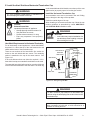
E. Install the Heat Shield and Horizontal Termination Cap
Heat Shield Requirements for Horizontal Termination
For all horizontally vented appliances, a heat shield MUST
be placed 1 in. above the top of the vent between the wall
shield and the base of the termination cap.
There are two sections of the heat shield. One section at-
taches to the wall shield with two screws. The remaining
section is attached to the cap in the same manner. See
Figure 2.16.
If the wall thickness does not allow the required 1-1/2 in.
heat shield overlap, an extended heat shield must be used.
The extended heat shield will need to be cut to the thickness
of the wall and be attached to the wall shield. The small leg
A 1-1/2 in. minimum overlap MUST be maintained on
the telescoping fl ue section of the cap.
WARNING
Note: Where required, an exterior wall fl ashing is available.
When penetrating a brick wall, a brick extension kit is
available for framing the brick.
INTERIOR
Heat Shield or
Extended
Heat Shield
Wall Shield
Inner Vent
Outer Vent
Rear Vent
Heat Shield
1-1/2 in. (38 mm) min.
overlap
EXTERIOR
SHEATHING
Figure 2.16 Venting through the Wall
on the extended heat shield should rest on the top of the vent
(pipe section) to properly space it from the pipe section.
Install the Horizontal Termination Cap
Vent termination must not be recessed in the wall. Siding
may be brought to the edge of the cap base.
Caulk the outside edges of the cap.
When installing a horizontal termination cap, follow the cap
location guidelines as prescribed by current ANSI Z223.1
and CAN/CGA-B149 installation codes.

Hearth & Home Technologies Inc. • Cinch Pipe & Term Caps • 4033-900 Rev K • 05/05
10
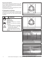
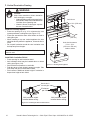
F. Vertical Penetration Framing
Note: The fi restop spacer is not required if attic insulation
shield is used.
Install Attic Insulation Shield
• Frame opening for attic insulation shield.
• Attic insulation shield may be installed above or below
ceiling (see Figure 2.18).
• Secure with three fasteners on each side.
• Fold tabs at top of attic shield in toward vent pipe. Tabs
must keep vent pipe centered within shield.
• Field construct additional shield height if insulation is
deeper than height of attic shield.
Attic Above
10 in. (254 mm)
Hole should measure
10 in. x 10 in.
(254 mm x 254 mm)
inside to inside
10 in.
(254 mm)
Figure 2.17 Installing Firestop Spacer
3 fasteners
per side
Attic insulation shield
installed below ceiling.
Attic insulation shield
installed above ceiling.
Bend tabs in
around pipe
Figure 2.18 Installing the Attic Insulation Shield
Fire Risk
Keep loose materials or blown insulation
from touching the vent pipe.
• National building codes recommend using
attic shield to keep loose materials/blown
insulation from contacting vent.
• Hearth & Home Technologies requires
the use of an attic shield.
WARNING
Install the Firestop Spacer
• Frame an opening 10 in. by 10 in. whenever the vent
system penetrates a ceiling/fl oor (see Figure 2.17).
• Frame the area with the same sized lumber as used in
ceiling/fl oor joist.
• When installing a top vent vertical appliance the hole
should be directly above the appliance, unless the fl ue is
offset.
• Do not pack insulation around the vent. Insulation must
be kept away from the pipe.

Hearth & Home Technologies Inc. • Cinch Pipe & Term Caps • 4033-900 Rev K • 05/05
11
Figure 2.20 Secure with Screws
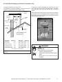
G. Install Roof Flashing and Vertical Termination Cap
To attach the vertical termination cap, slide the inner collar
of the cap into the inner fl ue of the pipe section and place
the outer collar of the cap over the outer fl ue of the pipe
section.
Secure with three screws into the outer fl ue. Secure the cap
by driving the three self-tapping screws (supplied) through
the pilot holes in the outer collar of the cap into the outer fl ue
of the pipe (see Figure 2.20).
Horizontal
overhang
12
X
20 in.
(508 mm)
Lowest
Discharge
Opening
Termination
Cap
Roof Pitch
is X / 12
Vertical
wall
H (min.) - Minimum height
from roof to lowest
discharge opening.
24 in. min.
(610 mm)
Roof Pitch H (Min.) Ft. Roof Pitch H (Min.) Ft.
Flat to 6/12 1.0* Over 11/12 to 12/12 4.0
6/12 to 7/12 1.25* Over 12/12 to 14/12 5.0
Over 7/12 to 8/12 1.5* Over 14/12 to 16/12 6.0
Over 8/12 to 9/12 2.0* Over 16/12 to 18/12 7.0
Over 9/12 to 10/12 2.5 Over 18/12 to 20/12 7.5
Over 10/12 to 11/12 3.25 Over 20/12 to 21/12 8.0
* 3 ft. minimum in snow regions
Storm Collar
Roof
Flashing
Figure 2.19 Minimum Height from Roof to Lowest Discharge
Opening
To install roof fl ashing see Figure 2.19.
For installation of vertical termination cap see minimum vent
heights for various pitched roofs (Figure 2.19) .
Fire Risk
Explosion Risk
Inspect external vent cap regularly.
• Ensure no debris blocks cap.
• Combustible materials blocking cap may
ignite.
• Restricted air flow affects burner
operation.
WARNING
Storm
Collar
Termination Cap
(1 of three)
Caulk
Screws
Brackets/
Bolts

Hearth & Home Technologies Inc. • Cinch Pipe & Term Caps • 4033-900 Rev K • 05/05
12
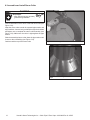
H. Assemble and Install Storm Collar
Connect both halves of the storm collar with two screws (see
Figure 2.21).
Wrap the storm collar around the exposed pipe section and
align brackets. Insert a bolt (provided) through the brackets
and tighten nut to complete the storm collar assembly (see
Figure 2.22). Make sure the collar is tight against the pipe
section.
Slide the assembled storm collar down the pipe section until
it rests on the roof fl ashing (see Figure 2.19).
Caulk around the top of the storm collar.
Sharp Edges!
• Wear protective gloves and safety
glasses during installation.
CAUTION
Figure 2.22 Assembling the Storm Collar Around the
Pipe
Figure 2.21 Assembling the Storm Collar
-
 1
1
-
 2
2
-
 3
3
-
 4
4
-
 5
5
-
 6
6
-
 7
7
-
 8
8
-
 9
9
-
 10
10
-
 11
11
-
 12
12


Hearth and Home Technologies DRC-RADIUS User manual
- Type
- User manual
Ask a question and I''ll find the answer in the document
Finding information in a document is now easier with AI
Related papers
-
Hearth and Home Technologies DV3732SBI User manual
-
-
-
-
-
-
-
Heat & Glo 6000GCF-IPI User manual
-
-
Other documents
-
Heat & Glo LifeStyle Indoor Fireplace 36DV User manual
-
-
-
-
Quadra-Fire QV32B-A Owner's manual
-
-
Heatilator Indoor Fireplace IDV4833IT User manual
-
Heatiator Indoor Fireplace NNXT4236IL NNXT3933I User manual
-
Majestic fireplaces QUARTZ32IL Installation guide
-