
Document No.: M-W3338AE-4.0
ANRITSU CORPORATION
•
For safety and warning information, please read this
manual before attempting to use the equipment.
•
Additional safety and warning information is provided
within the
MS2830A Signal Analyzer Operation Manual
(Mainframe Operation), MS2840A Signal Analyzer
Operation Manual (Mainframe Operation) and the
MS2830A/MS2840A Signal Analyzer Vector Signal
Generator Option Operation Manual (Operation).
Please also refer to these documents before using the
equipment.
•
Keep this manual with the equipment.
Fourth Edition
MS2830A/MS2840A
Signal Analyzer
Vector Signal Generator
Operation Manual
Remote Control

ii
Safety Symbols
To prevent the risk of personal injury or loss related to equipment malfunction, Anritsu Corporation uses the
following safety symbols to indicate safety-related information. Ensure that you clearly understand the meanings of
the symbols BEFORE using the equipment. Some or all of the following symbols may be used on all Anritsu
equipment. In addition, there may be other labels attached to products that are not shown in the diagrams in this
manual.
Symbols used in manual
This indicates a very dangerous procedure that could result in serious injury or
death if not performed properly.
This indicates a hazardous procedure that could result in serious injury or death if
not performed properly.
This indicates a hazardous procedure or danger that could result in light-to-severe
injury, or loss related to equipment malfunction, if proper precautions are not taken.
Safety Symbols Used on Equipment and in Manual
The following safety symbols are used inside or on the equipment near operation locations to provide information
about safety items and operation precautions. Ensure that you clearly understand the meanings of the symbols and
take the necessary precautions BEFORE using the equipment.
This indicates a prohibited operation. The prohibited operation is indicated
symbolically in or near the barred circle.
This indicates an obligatory safety precaution. The obligatory operation is
indicated symbolically in or near the circle.
This indicates a warning or caution. The contents are indicated symbolically in or
near the triangle.
This indicates a note. The contents are described in the box.
These indicate that the marked part should be recycled.
MS2830A/MS2840A
Signal Analyzer Vector Signal Generator
Operation Manual Remote Control
15 December 2009 (First Edition)
13 May 2016 (Fourth Edition)
Copyright © 2009-2016, ANRITSU CORPORATION.
All rights reserved. No part of this manual may be reproduced without the prior written permission of the
publisher.
The contents of this manual may be changed without prior notice.
Printed in Japan
DANGER
WARNING
CAUTION

iii
Notes On Export Management
This product and its manuals may require an Export License/Approval by
the Government of the product's country of origin for re
-export
from your
country.
Before re
-
exporting the product or manuals, please contact us to confirm
whet
her they are export-controlled items or not.
When you dispose of export
-
controlled items, the products/manuals need
to be broken/shredded so as not to be unlawfully used for military purpose.

iv

I
About This Manual
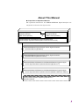
Composition of Operation Manuals
The operation manuals for the MS2830A/MS284A Signal Analyzer are
comprised as shown in the figure below.
MS2830A/MS2840A Signal Analyzer Vector Signal Generator
Operation Manual (Operation)
MS2690A/MS2691A/MS2692A and MS2830A/MS2840A Signal Analyzer
Vector Signal Generator Operation Manual (Standard Waveform Pattern)
Communication System Supporting IQproducer
TM
Operation Manual
MS2690A/MS2691A/MS2692A and MS2830A/MS2840A Signal Analyzer
Vector Signal Generator Operation Manual (IQproducer
™)
MS2830A/MS2840A Signal Analyzer Vector Signal Generator
Operation Manual (Remote Control)
MS2840A Signal Analyzer
Operation Manual
(Main Frame Operation)
MS2690A/MS2691A/MS2692A and MS2830A/MS2840A
Signal Analyzer Operation Manual (Main Frame Remote Control)
MS2830A Signal Analyzer
Operation Manual
(Main Frame Operation)
Or

II
Signal Analyzer Operation Manual (Mainframe Operation)
Signal Analyzer Operation Manual (Mainframe Remote Control)
These manuals describe basic operating methods, maintenance
procedures, common functions, and common remote control of the signal
analyzer mainframe.
Vector Signal Generator Operation Manual (Operation)
This manual describes functions, operating methods, and so on of the
vector signal generator (option).
Vector Signal Generator Operation Manual (Remote Control) (This
manual)
This manual describes remote control of the vector signal generator
(option).
Vector Signal Generator Operation Manual (IQproducer
TM
)
This manual describes functions, operating methods, and so on of the
IQproducer, which is application software used with the vector signal
generator (option).
Vector Signal Generator Operation Manual (Standard Waveform
Pattern)
This manual describes details on the standard waveform pattern data
used with the vector signal generator (option).

1
3
4
III
2
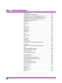
Table of Contents
About This Manual........................................ I
Chapter 1 Overview .................................... 1-1
1.1 Overview ....................................................................... 1-2
Chapter 2 SCPI Device Message............... 2-1
2.1 Setting Frequency ......................................................... 2-3
2.2 Setting Level ................................................................. 2-9
2.3 Controlling Waveform Patterns in Waveform Memory .. 2-26
2.4 Controlling Waveform Patterns in HDD/SSD ................ 2-36
2.5 Modulation and AWGN Settings ................................... 2-44
2.6 External In/Output Settings ........................................... 2-52
2.7 External output signal settings ...................................... 2-66
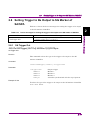
2.8 Setting Trigger to Be Output to SG Marker
of SA/SPA ..................................................................... 2-77
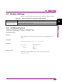
2.9 Display Settings ............................................................ 2-79
2.10 Other Settings ............................................................... 2-81
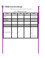
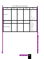
Chapter 3 Native Device Message List ..... 3-1
3.1
IEEE488.2 Common Device Messages ........................ 3-2
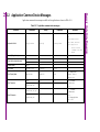
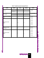
3.2
Application Common Device Messages ....................... 3-4
3.3
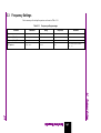
Frequency Settings ....................................................... 3-7
3.4
Level Settings ............................................................... 3-8
3.5
Controlling Waveform Patterns in Waveform
Memory ......................................................................... 3-10
3.6
Controlling Waveform Patterns in HDD/SSD ................ 3-12
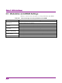
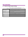
3.7
Modulation and AWGN Settings ................................... 3-13
3.8
External Input Signal Settings ....................................... 3-14
3.9
External Output Signal Settings .................................... 3-16
3.10
Setting Trigger to Be Output to SG Marker of
SA/SPA ......................................................................... 3-17
3.11
Display Settings ............................................................ 3-18
Chapter 4 Native Device Message Details 4-1

IV.


Chapter 1 Overview
1-2.
1.1 Overview
Automatic measurement can be performed by using this instrument in
connection with an external controller (PC). This instrument is
standardly equipped with GPIB, Ethernet, and USB interfaces. You can
also select a remote control command from the SCPI mode, which is a
command format defined by the SCPI Consortium, and Native mode,
which is our unique format.
See the
MS2690A/MS2691A/MS2692A and MS2830A/MS2840A Signal
Analyzer Operation Manual (Mainframe Remote Control)
for how to
switch the language mode.
You can use the Native mode by converting SCPI commands into Native
ones. See the
MS2690A/MS2691A/MS2692A and MS2830A/MS2840A
Signal Analyzer Operation Manual (Mainframe Remote Control)
for
details.

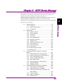
Chapter 2 SCPI Device Message
2-1
2
SCPI Device Message
This chapter describes the detailed specifications of SCPI remote control
commands for executing the functions of this application. The device
messages are listed according to function. Refer to the
MS2690A/MS2691A/MS2692A and MS2830A/MS2840A Signal Analyzer
Operation Manual (Mainframe Remote Control)
for detailed
specifications off the IEEE488.2 common device messages and application
common device messages.
2.1
Setting Frequency ......................................................... 2-3
2.1.1
Frequency ......................................................... 2-4
2.1.2
Frequency Step Value ...................................... 2-6
2.1.3
RF Spectrum .................................................... 2-8
2.2
Setting Level ................................................................. 2-9
2.2.1
Output Level Unit ............................................ 2-10
2.2.2
Volt Unit Display ............................................. 2-11
2.2.3
RF Output ....................................................... 2-12
2.2.4
Unit Power ...................................................... 2-13
2.2.5
SG Level Calibration....................................... 2-14
2.2.6
Relative Level Value ....................................... 2-15
2.2.7
Relative Level ................................................. 2-17
2.2.8
Reference of Relative Level ........................... 2-18
2.2.9
Level Status List ............................................. 2-19
2.2.10
Level Offset Value .......................................... 2-20
2.2.11
Level Offset .................................................... 2-21
2.2.12
Output Level Step Value ................................ 2-22
2.2.13
Output Level ................................................... 2-23
2.3
Controlling Waveform Patterns in Waveform
Memory ....................................................................... 2-26
2.3.1
Delete Pattern file on Wave Memory .............. 2-27
2.3.2
Delete All Pattern files on Wave Memory ....... 2-28
2.3.3
List of Loaded Pattern Files ............................ 2-29
2.3.4
Number of loaded pattern files ....................... 2-30
2.3.5
Wave Memory Size ........................................ 2-31
2.3.6
Select Pattern file on Wave Memory .............. 2-32
2.3.7
Waveform Restart ........................................... 2-34
2.3.8
ARB Status Query .......................................... 2-35
2.4
Controlling Waveform Patterns in HDD/SSD .............. 2-36
2.4.1
Copy pattern file to HDD/SSD ........................ 2-37
2.4.2
Delete Pattern file on HDD/SSD ..................... 2-38
2.4.3
Load Pattern File / Query Load Status and
Wave Memory ................................................ 2-39
2.4.4
Cancel Loading ............................................... 2-41
2.4.5
Pattern File Version ........................................ 2-42
2.4.6
HDD/SSD Size ............................................... 2-43

Chapter 2 SCPI Device Message
2-2
2.5
Modulation and AWGN Settings ................................. 2-44
2.5.1
Modulation ...................................................... 2-45
2.5.2
AWGN ............................................................ 2-46
2.5.3
C/N Ratio ........................................................ 2-47
2.5.4
Target of C/N Setting ...................................... 2-49
2.5.5
Carrier Power ................................................. 2-50
2.5.6
Sampling Clock ............................................... 2-51
2.6
External In/Output Settings ......................................... 2-52
2.6.1
Pulse Modulation Source ............................... 2-53
2.6.2
External Trigger Mode .................................... 2-54
2.6.3
External Trigger .............................................. 2-55
2.6.4
External Trigger Source ................................. 2-56
2.6.5
External Trigger Delay .................................... 2-57
2.6.6
External Trigger Delay Time ........................... 2-59
2.6.7
External Trigger Edge..................................... 2-60
2.6.8
Baseband Reference Clock Source ............... 2-61
2.6.9
Baseband Reference Clock ............................ 2-62
2.6.10
Frame Count ................................................... 2-64
2.6.11
Remote Command Trigger ............................. 2-65
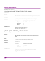
2.7
External output signal settings .................................... 2-66
2.7.1
Marker Polarity ............................................... 2-67
2.7.2
Marker Edit ..................................................... 2-69
2.7.3
Marker Pulse Cycle Value .............................. 2-71
2.7.4
Marker Pulse Start Offset Value ..................... 2-73
2.8
Setting Trigger to Be Output to SG Marker of
SA/SPA ....................................................................... 2-77
2.8.1
SA Trigger Out ................................................ 2-77
2.9
Display Settings .......................................................... 2-79
2.9.1
SG Window Position ....................................... 2-79
2.10
Other Settings ............................................................. 2-81
2.10.1
SG Status ....................................................... 2-81

2.1 Setting Frequency
2-3
2
SCPI Device Message
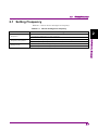
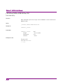
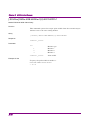
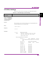
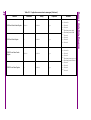
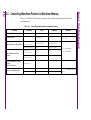
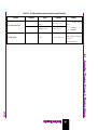
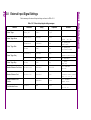
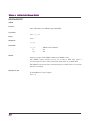
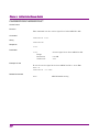
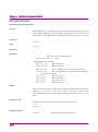
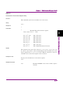
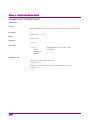
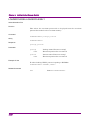
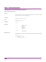
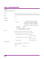
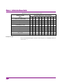
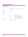
2.1 Setting Frequency
Table 2.1-1 shows device messages for frequency.
Table 2.1-1 Device messages for frequency
Function Device Messages
Frequency
[:SOURce]:FREQuency[:CW|:FIXed] <freq>
[:SOURce]:FREQuency[:CW|:FIXed]?
Frequency Step Value
[:SOURce]:FREQuency:STEP[:INCRement] <numeric_value>
[:SOURce]:FREQuency:STEP[:INCRement]?
RF Spectrum
[:SOURce]:DM:POLarity[:ALL] NORMal|INVert
[:SOURce]:DM:POLarity[:ALL]?

Chapter 2 SCPI Device Message
2-4
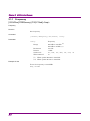
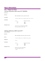
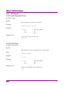
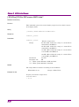
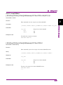
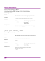
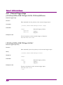
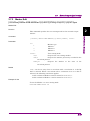
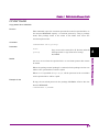
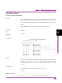
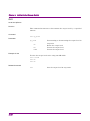
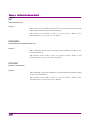
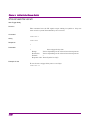
2.1.1 Frequency
[:SOURce]:FREQuency[:CW|:FIXed] <freq>
Frequency
Function
Sets frequency
Command
[:SOURce]:FREQuency[:CW|:FIXed] <freq>
Parameter
<freq>
Frequency
Range 250 kHz to 3.6 GHz
(*)
250 kHz to 6 GHz
(**)
Resolution 0.01 Hz
Default 1 GHz
Suffix code
HZ, KHZ, KZ, MHZ, MZ, GHZ, GZ
When omitted:
Hz
(*) When option 020/120 is installed.
(**) When option 021/121 is installed.
Example of Use
To set the frequency to 800 MHz
FREQ 800MHZ

2.1 Setting Frequency
2-5
2
SCPI Device Message
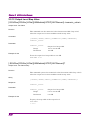
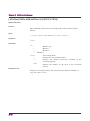
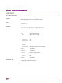
[:SOURce]:FREQuency[:CW|:FIXed]?
Frequency Query
Function
This command queries the frequency.
Query
[:SOURce]:FREQuency[:CW|:FIXed]?
Response
<freq>
Parameter
<freq>
Frequency
Range 250 kHz to 3.6 GHz
(*)
250 kHz to 6 GHz
(**)
Resolution 0.01 Hz
Default 1 GHz
(*) When option 020/120 is installed.
(**) When option 021/121 is installed.
Example of Use
To query the frequency.
FREQ?
> 800000000.00

Chapter 2 SCPI Device Message
2-6
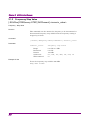
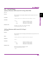
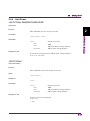
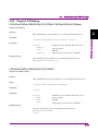
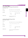
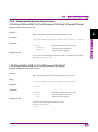
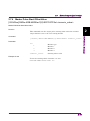
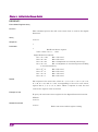
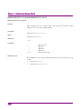
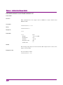
2.1.2 Frequency Step Value
[:SOURce]:FREQuency:STEP[:INCRement] <numeric_value>
Frequency - Step Value
Function
This command sets the amount the frequency to be incremented or
decremented (frequency step width) when the frequency setting is
stepped up or down.
Command
[:SOURce]:FREQuency:STEP[:INCRement] <numeric_value>
Parameter
<numeric_value> Frequency step width
Range 0.01 Hz to 1 GHz
Resolution 0.01 Hz
Default 100 kHz
Suffix code
HZ, KHZ, KZ, MHZ, MZ, GHZ, GZ
When omitted:
Hz
Example of Use
To set the frequency step width to 200 kHz.
FREQ:STEP 200KHZ

2.1 Setting Frequency
2-7
2
SCPI Device Message
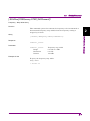
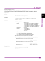
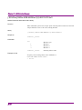
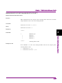
[:SOURce]:FREQuency:STEP[:INCRement]?
Frequency - Step Value Query
Function
This command queries the amount the frequency to be incremented or
decremented (frequency step width) when the frequency setting is
stepped up or down.
Query
[:SOURce]:FREQuency:STEP[:INCRement]?
Response
<numeric_value>
Parameter
<numeric_value>
Frequency step width
Range 0.01 Hz to 1 GHz
Resolution 0.01 Hz
Default 100 kHz
Example of Use
To query the frequency step width.
FREQ:STEP?
> 200000.00

Chapter 2 SCPI Device Message
2-8
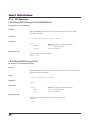
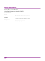
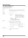
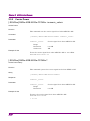
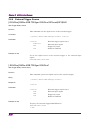
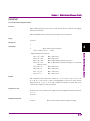
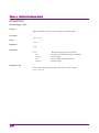
2.1.3 RF Spectrum
[:SOURce]:DM:POLarity[:ALL] NORMal|INVert
RF Spectrum - Reverse/Normal
Function
This command whether to invert spectrum of the output waveform
(reverses I and Q).
Command
[:SOURce]:DM:POLarity[:ALL] <mode>
Parameter
<mode>
Whether to invert output waveform
NORMal Normal:
Do not invert
INVert Reverse:
Invert
Example of Use
To invert the output waveform.
DM:POL INV
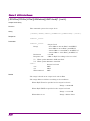
[:SOURce]:DM:POLarity[:ALL]?
RF Spectrum - Reverse/Normal Query
Function
This command queries the status of the spectrum invert (reverses I and
Q) of the output waveform.
Query
[:SOURce]:DM:POLarity[:ALL]?
Response
<mode>
Parameter
<mode>
Whether to invert output waveform
NORM Normal:
Do not invert
INV Reverse:
Invert
Example of Use
To query the invert status of the output waveform.
DM:POL?
> INV

2.2 Setting Level
2-9
2
SCPI Device Message
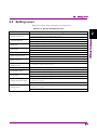
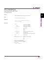
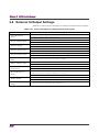
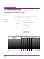
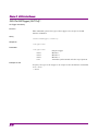
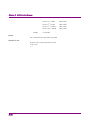
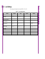
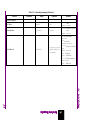
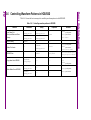
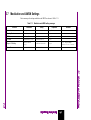
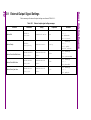
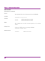
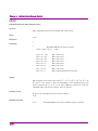
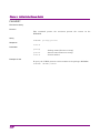
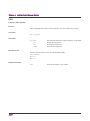
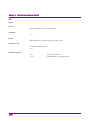
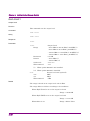
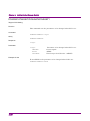
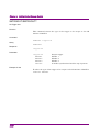
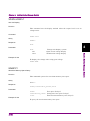
2.2 Setting Level
Table 2.2-1 shows device messages for setting level.
Table 2.2-1 Device messages for level
Function Device Messages
Output Level Unit
:DISPlay:ANNotation:AMPLitude:UNIT DBM|DBU
:DISPlay:ANNotation:AMPLitude:UNIT?
Volt Unit Display
:DISPlay:ANNotation:AMPLitude:UNIT:VOLTage EMF|TERM
:DISPlay:ANNotation:AMPLitude:UNIT:VOLTage?
RF Output
:OUTPut[:STATe] ON|OFF|1|0
:OUTPut[:STATe]?
Unit Power
:UNIT:POWer DBM|DBUV|DBUVEMF
:UNIT:POWer?
SG Level Calibration
[:SOURce]:POWer:ALC:SEARch {ONCE}
Relative Level Value
[:SOURce]:POWer:REFerence:AMPLitude <numeric_value>
[:SOURce]:POWer:REFerence:AMPLitude?
Relative Level
[:SOURce]:POWer:REFerence:STATe ON|OFF|1|0
[:SOURce]:POWer:REFerence:STATe?
Reference of
Relative Level
[:SOURce]:POWer:REFerence?
Level Status List
[:SOURce]:POWer:SETTing?
Level Offset Value
[:SOURce]:POWer[:LEVel][:IMMediate]:OFFSet <numeric_value>
[:SOURce]:POWer[:LEVel][:IMMediate]:OFFSet?
Level Offset
[:SOURce]:POWer[:LEVel][:IMMediate]:OFFSet:STATe ON|OFF|1|0
[:SOURce]:POWer[:LEVel][:IMMediate]:OFFSet:STATe?
Output Level Step Value
[:SOURce]:POWer[:LEVel][:IMMediate]:STEP[:INCRement]
<numeric_value>
[:SOURce]:POWer[:LEVel][:IMMediate]:STEP[:INCRement]?
Output Level
[:SOURce]:POWer[:LEVel][:IMMediate][:AMPLitude]
<numeric_value>
[:SOURce]:POWer[:LEVel][:IMMediate][:AMPLitude]? {<unit>}

Chapter 2 SCPI Device Message
2-10
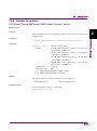
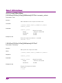
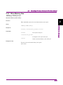
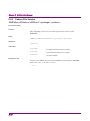
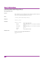
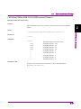
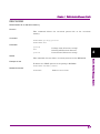
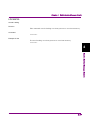
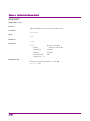
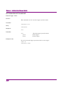
2.2.1 Output Level Unit
:DISPlay:ANNotation:AMPLitude:UNIT DBM|DBU
Level Unit
Function
This command sets the output level unit.
Command
:DISPlay:ANNotation:AMPLitude:UNIT <unit>
Parameter
<unit>
Output level unit
DBM
dBm
DBU
dB
µ
V
Example of Use
To set the level setting unit to dBm.
DISP:ANN:AMPL:UNIT DBM
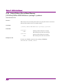
:DISPlay:ANNotation:AMPLitude:UNIT?
Level Unit Query
Function
This command queries the output level unit.
Query
:DISPlay:ANNotation:AMPLitude:UNIT?
Response
<unit>
Parameter
<unit>
Output level unit
DBM
dBm
DBU
dB
µ
V
Example of Use
To query the level setting unit.
DISP:ANN:AMPL:UNIT?
> DBM
Page is loading ...
Page is loading ...
Page is loading ...
Page is loading ...
Page is loading ...
Page is loading ...
Page is loading ...
Page is loading ...
Page is loading ...
Page is loading ...
Page is loading ...
Page is loading ...
Page is loading ...
Page is loading ...
Page is loading ...
Page is loading ...
Page is loading ...
Page is loading ...
Page is loading ...
Page is loading ...
Page is loading ...
Page is loading ...
Page is loading ...
Page is loading ...
Page is loading ...
Page is loading ...
Page is loading ...
Page is loading ...
Page is loading ...
Page is loading ...
Page is loading ...
Page is loading ...
Page is loading ...
Page is loading ...
Page is loading ...
Page is loading ...
Page is loading ...
Page is loading ...
Page is loading ...
Page is loading ...
Page is loading ...
Page is loading ...
Page is loading ...
Page is loading ...
Page is loading ...
Page is loading ...
Page is loading ...
Page is loading ...
Page is loading ...
Page is loading ...
Page is loading ...
Page is loading ...
Page is loading ...
Page is loading ...
Page is loading ...
Page is loading ...
Page is loading ...
Page is loading ...
Page is loading ...
Page is loading ...
Page is loading ...
Page is loading ...
Page is loading ...
Page is loading ...
Page is loading ...
Page is loading ...
Page is loading ...
Page is loading ...
Page is loading ...
Page is loading ...
Page is loading ...
Page is loading ...
Page is loading ...
Page is loading ...
Page is loading ...
Page is loading ...
Page is loading ...
Page is loading ...
Page is loading ...
Page is loading ...
Page is loading ...
Page is loading ...
Page is loading ...
Page is loading ...
Page is loading ...
Page is loading ...
Page is loading ...
Page is loading ...
Page is loading ...
Page is loading ...
Page is loading ...
Page is loading ...
Page is loading ...
Page is loading ...
Page is loading ...
Page is loading ...
Page is loading ...
Page is loading ...
Page is loading ...
Page is loading ...
Page is loading ...
Page is loading ...
Page is loading ...
Page is loading ...
Page is loading ...
Page is loading ...
Page is loading ...
Page is loading ...
Page is loading ...
Page is loading ...
Page is loading ...
Page is loading ...
Page is loading ...
Page is loading ...
Page is loading ...
Page is loading ...
Page is loading ...
Page is loading ...
Page is loading ...
Page is loading ...
Page is loading ...
Page is loading ...
Page is loading ...
Page is loading ...
Page is loading ...
Page is loading ...
Page is loading ...
Page is loading ...
Page is loading ...
Page is loading ...
Page is loading ...
Page is loading ...
Page is loading ...
Page is loading ...
Page is loading ...
Page is loading ...
Page is loading ...
Page is loading ...
Page is loading ...
Page is loading ...
Page is loading ...
Page is loading ...
Page is loading ...
Page is loading ...
Page is loading ...
Page is loading ...
Page is loading ...
Page is loading ...
Page is loading ...
Page is loading ...
Page is loading ...
Page is loading ...
Page is loading ...
Page is loading ...
Page is loading ...
Page is loading ...
Page is loading ...
Page is loading ...
Page is loading ...
Page is loading ...
Page is loading ...
Page is loading ...
-
 1
1
-
 2
2
-
 3
3
-
 4
4
-
 5
5
-
 6
6
-
 7
7
-
 8
8
-
 9
9
-
 10
10
-
 11
11
-
 12
12
-
 13
13
-
 14
14
-
 15
15
-
 16
16
-
 17
17
-
 18
18
-
 19
19
-
 20
20
-
 21
21
-
 22
22
-
 23
23
-
 24
24
-
 25
25
-
 26
26
-
 27
27
-
 28
28
-
 29
29
-
 30
30
-
 31
31
-
 32
32
-
 33
33
-
 34
34
-
 35
35
-
 36
36
-
 37
37
-
 38
38
-
 39
39
-
 40
40
-
 41
41
-
 42
42
-
 43
43
-
 44
44
-
 45
45
-
 46
46
-
 47
47
-
 48
48
-
 49
49
-
 50
50
-
 51
51
-
 52
52
-
 53
53
-
 54
54
-
 55
55
-
 56
56
-
 57
57
-
 58
58
-
 59
59
-
 60
60
-
 61
61
-
 62
62
-
 63
63
-
 64
64
-
 65
65
-
 66
66
-
 67
67
-
 68
68
-
 69
69
-
 70
70
-
 71
71
-
 72
72
-
 73
73
-
 74
74
-
 75
75
-
 76
76
-
 77
77
-
 78
78
-
 79
79
-
 80
80
-
 81
81
-
 82
82
-
 83
83
-
 84
84
-
 85
85
-
 86
86
-
 87
87
-
 88
88
-
 89
89
-
 90
90
-
 91
91
-
 92
92
-
 93
93
-
 94
94
-
 95
95
-
 96
96
-
 97
97
-
 98
98
-
 99
99
-
 100
100
-
 101
101
-
 102
102
-
 103
103
-
 104
104
-
 105
105
-
 106
106
-
 107
107
-
 108
108
-
 109
109
-
 110
110
-
 111
111
-
 112
112
-
 113
113
-
 114
114
-
 115
115
-
 116
116
-
 117
117
-
 118
118
-
 119
119
-
 120
120
-
 121
121
-
 122
122
-
 123
123
-
 124
124
-
 125
125
-
 126
126
-
 127
127
-
 128
128
-
 129
129
-
 130
130
-
 131
131
-
 132
132
-
 133
133
-
 134
134
-
 135
135
-
 136
136
-
 137
137
-
 138
138
-
 139
139
-
 140
140
-
 141
141
-
 142
142
-
 143
143
-
 144
144
-
 145
145
-
 146
146
-
 147
147
-
 148
148
-
 149
149
-
 150
150
-
 151
151
-
 152
152
-
 153
153
-
 154
154
-
 155
155
-
 156
156
-
 157
157
-
 158
158
-
 159
159
-
 160
160
-
 161
161
-
 162
162
-
 163
163
-
 164
164
-
 165
165
-
 166
166
-
 167
167
-
 168
168
-
 169
169
-
 170
170
-
 171
171
-
 172
172
-
 173
173
-
 174
174
-
 175
175
-
 176
176
-
 177
177
-
 178
178
-
 179
179
-
 180
180
-
 181
181
-
 182
182


Anritsu MS2840A Operating instructions
- Type
- Operating instructions
- This manual is also suitable for
Ask a question and I''ll find the answer in the document
Finding information in a document is now easier with AI
Related papers
-
Anritsu MS2830A Operating instructions
-
-
-
-
-
-
-
-
-
Other documents
-
 Perfect Prime TC0301 Datalogger Thermometer User manual
-
 Kewtech KEW301 User manual
-
Tektronix WCA280A Programmer's Manual
-
Aeroflex 3413 Operating instructions
-
Rohde&Schwarz SMCV100B User manual
-
HP (Hewlett-Packard) 86140A User manual
-
EXFO IQS-2400 WDM Laser Source for IQS-500/600 User guide
-
-
-
Symmetricom 5071A Operating And Programming Manual

