Page is loading ...

41490-01 12/01/2005
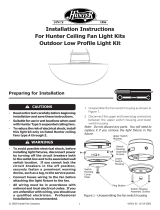
INSTALLATION INSTRUCTIONS FOR HUNTER
CEILING FAN LIGHT KITS MODELS:
28343, 28344, 28345, 28405, 28406, 28407, 28408, 28982, 28983, 28984, 28985, 28986, 28987
28330, 28331, 28332, 28333, 28334, 28335, 28336, 28337, 28338, 28339, 28340, 28341, 28342
WARNING
• To avoid possible electrical shock, before in-
stalling light fixtures, disconnect power by
turning off the circuit breakers both to the
outlet box and to its associated wall switch
location. If you cannot lock the circuit break-
ers in the off position, securely fasten a
prominent warning device, such as a tag, to
the service panel.
• Connect house wiring to the fan before at-
taching the light fixture to the fan.
• All wiring must be in accordance with na-
tional and local electrical codes and ANSI/
NFPA 70. If you are unfamiliar with wiring,
you should use a qualified electrician.
CAUTIONS
• Read entire text carefully before beginning in-
stallation and save these instructions.
• To reduce the risk of electrical shock, install
this light kit only on listed Hunter ceiling fan
models: Cote D’ Azur , Custom Home 2 ,
Captiva, 44” Dominion , Designer’s Choice,
ORBit, 52” Dominion , Marseille , Santa
Barbara, Belle Meade & Etruscan
STEP 1: REMOVING WIRING HARNESS
Before you can install the modular accessory light
kit, you must remove the wiring harness and its com-
ponents from the modular switch housing on the
fans listed above. You must then install the wiring
harness into the modular accessory light kit.
NOTE: Refer to Figure 1 for the steps listed below.
1. Locate the reversing switch and carefully remove
the two screws holding the reversing switch to
the switch housing. The reversing switch can now
be removed from the switch housing.
2. Remove the patented breakaway connector from
the fan pull chain.
3. Carefully loosen the bellmouth nut from the fan
pull chain and remove the fan pull chain switch
from the switch housing.
4. Locate and carefully remove the two capacitors
from the switch housing.
5. You have now disconnected the wiring harness
and its components from the switch housing and
are ready to install them into the modular acces-
sory light kit.
STEP 2: INSTALLING WIRING HARNESS
NOTE: Refer to Figure 1 for steps listed below.
1. Locate the two wires in the lower switch housing
labeled “ Connect Light Here” or “ For Light Use” .
One will be white, the other black/white. Unscrew
the wire nuts counterclockwise to expose the bare
metal leads.
2. Locate the white wire and the black wire coming
from the light fixture.
Connect the black wire from the light fixture to
the black/white wire from the lower switch hous-
ing.
Connect the white wire from the light fixture to
the white wire from the lower switch housing.
To fasten the wires, twist the two bare leads to-
gether. Place a wire nut over the intertwined length
of wire and twist clockwise until tight.
Fan Speed
Switch
Capacitor
Reverse Switch
M ulti-wire Plug
Connection
Capacitor
Bellmouth Nut
M 3 Housing
Assembly Screws
Light K it Lead W ires
and W ire Nuts
FIGURE 1

41490-01 12/01/2005
3. Insert the chain and fan pull chain switch through
the round opening on the side of the modular
accessory light kit. Thread the bellmouth nut over
the pull chain and hand tighten the bellmouth
nut.
4. Reattach the patented breakaway connector to
the end of the pull chain.
5. Insert the reversing switch into the square hole
on the side of the modular accessory light kit.
Install and tighten the two screws you removed
in Step 1, substep 1.
6. Carefully place the capacitors in the modular ac-
cessory light kit.
You have completed the assembly of the modular
accessory light kit and are ready for installing the
modular accessory light kit to the fan.
STEP 3: INSTALLING THE ACCESSORY
LIGHT KIT
NOTE: Refer to Figure 3 for the steps listed below.
1. Connect the lower (mutli-wire) plug connector
from the modular accessory light kit to the up-
per plug connector from the motor.
NOTE: Both plug connectors are polarized and will
only fit together one way. Make sure that both
connectors are properly aligned before connect-
ing them together. Incorrect connection could
cause improper operation and damage to the
product.
2. Place the modular accessory light kit over the up-
per switch housing. Align the side screw holes in
the upper switch housing and the modular acces-
sory light kit. Attach the modular accessory light
kit to the upper switch housing with the three
#6-32 X 3/8" housing assembly screws.
STEP 4: INSTALLING THE BULBS AND
GLOBES
NOTE: Refer to Figure 4 for the steps listed below.
1. Insert a globe into the cup.
2. Tighten the thumbscrews manually. Do Not
overtighten.
3. Repeat substeps 1 and 2 for the remaining three
globes.
4. Install a 60W medium base incandescent bulb into
each socket.
You have completed the installation of the modular
accessory light kit. Refer back to the “ Operating
Your Hunter Fan” section in the Installation/Owner’s
Manual provided with your Hunter fan for proper
operation instructions.
CUP
THUM B-
SCREW S
GLOBE
FIGURE 4
Hunter Fan Company
2500 Frisco Avenue
Memphis, TN 38114
USA
© 2005 Hunter Fan Co.
FIGURE 2
Fan Speed
Switch
Capacitor
Reverse Sw itch
M ulti-w ire Plug
Connection
Capacitor
Bellmouth Nut
#6-62 Housing
Assembly Screws
Bellmouth Nut
Light Switch
W ires to Light Sockets
CAUTION
Be sure no bare wire or wire strands are visible after
making connections.
UPPER SW ITCH
HOUSING
UPPER PLUG
CO NNECTOR
HOUSING ASSEM BLY
SCREW
FIGURE 3
LOW ER PLUG
CO NNECTOR
LIGHT K IT
/


