contents
POWER TOOL WARRANTY ................... 2
GENERAL SAFETY INSTRUCTIONS
FOR POWER TOOLS ........................... 2
ADDITIONAL SAFETY INSTRUCTIONS
FOR SCROLL SAW .............................. 3
MOTOR SPECIFICATIONS AND
ELECTRICAL REQUIREMENTS ............... 4
UNPACKING AND CHECKING CONTENTS ,, 5
ASSEMBLY
Assembling Steel Legs ........................ 6
Mounting Scroll Saw on Leg Set ............. 7
Mounting Scroll Saw to Workbench ........... 7
Mounting Scroll Saw to Mounting Board .... 8
Adjusting Guard ........................... 8
Installing Miter Lock Knob ..................... 8
Blade Installation and Tensioning
for Plain-End and Pin Type Blades .......... 9
To Install/Tension Plain End Blades ........ 9
Adjusting Insert To Table ................ t0
To Install/Tension Pin Type Blades .......... tl
To Remove Plain-End or Pin Type Blades., 11
Adjusting the Blade Square to Table ........ 13
Installation of Bevel Scales ................ 14
unpacking and checking
_1 COMBINATION SQUARE
GETTING TO KNOW YOUR SCROLL SAW
Tension Control Knob .................. 15
Guard Lock Knobs ............................... 15
Guard ...................................... 15
Blower Tube .................................. 15
Blade Holder Retaining Clips ............. 15
Blade Holders ................................ 15
Blade Holder Pockets ....................... 15
Miter Gauge Lock Knob ................... 15
Table Insert ................................ 15
Blade Storage ................................... 15
Bevel Lock Knob ............................... !5
Bevel Scales .................................. 15
On-Off Switch .................................. 15
Blade Storage .................................. 16
BASIC SCROLL SAW OPERATION
Sawing/Scrolling ............................. 17
Bevel Setting/Cutting ......................... 17
Use of Miter Gauge-Crosscutting .......... 18
Use of Miter Gauge-Ripping ............... 18
MAINTENANCE .................................. 18
RECOMMENDED ACCESSORIES ............... 19
TROUBLESHOOTING ....................... 19
REPAIR PARTS ................................ 20
contents
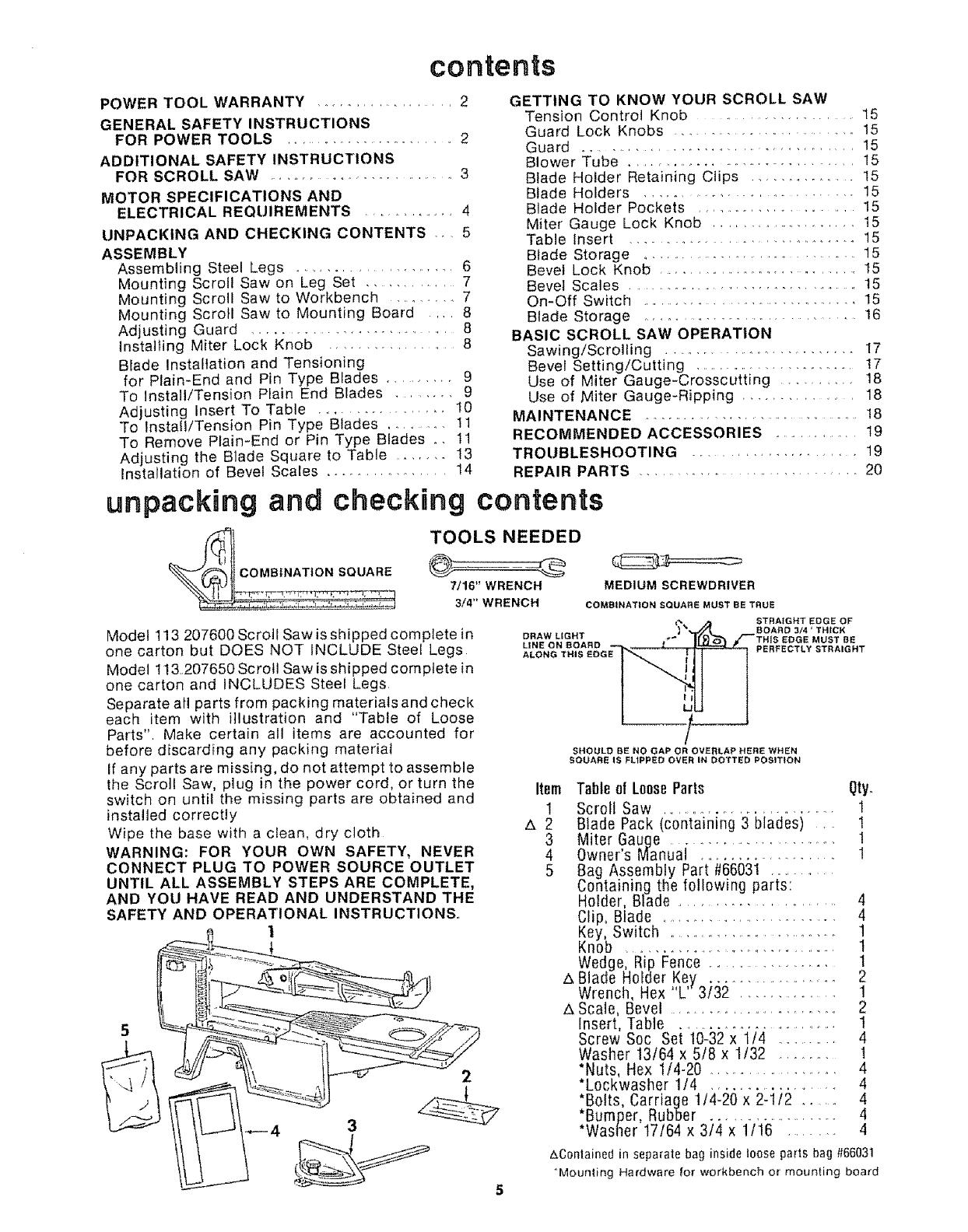
TOOLS NEEDED
7/16" WRENCH
3/4" WRENCH
Model 113 207600 Scroll Saw isshipped complete in
one carton but DOES NOT INCLUDE Steel Legs
Model 113,,207650 Scroll Saw is shipped complete in
one carton and INCLUDES Steel Legs
Separate all parts from packing materials and check
each item with illustration and "Table of Loose
Parts", Make certain all items are accounted for
before discarding any packing material
If any parts are missing, do not attempt to assemble
the Scroll Saw, plug in the power cord, or turn the
switch on until the missing parts are obtained and
installed correctly
Wipe the base with a clean, dry cloth
WARNING: FOR YOUR OWN SAFETY, NEVER
CONNECT PLUG TO POWER SOURCE OUTLET
UNTIL ALL ASSEMBLY STEPS ARE COMPLETE,
AND YOU HAVE READ AND UNDERSTAND THE
SAFETY AND OPERATIONAL INSTRUCTIONS,.
1
5
3
2
DRAW LIGHT
LINE ON 8CARD
ALONG THIS EDGE
MEDIUM SCREWDRIVER
COMBINATION SQUARE MUST BE TRUE
_. STRAtGHT EDGE OF
A BOARD 314' THICK
_'" BE
PERFECTLY STRAIGHT
Item
1
_2
3
4
5
SHOULD BE NO GAP OR OVERLAP HERE WHEN
SQUARE IS FLIPPED OVER IN DOTTED POSITION
A
A
Table 0f LooseParts Qty.
Scroll Saw ............................ 1
Blade Pack (containing 3 blades) ..... !
Miter Gauge ........................... !
Owner's Manual .................... 1
Bag Assembly Part #66031 ............
Containing the following parts:
Holder, Blade ..................... 4
Clip, Blade ........................... 4
Key, Switch ............................... 1
Knob ................................. 1
Wedge, Rip Fence ............... 1
Blade Holder Key .................... 2
Wrench, Hex "L"3f32 ............. 1
Scale, Bevel ......................... 2
Insert, Table ............................ I
Screw Soc Set t0-32 x 1/4 ........ 4
Washer 13/64 x 5/8 x 1/32 ........ t
*Nuts, Hex 1t4-20 .................. 4
*L0ckwasher 1/4 ................. 4
*Bolts, Carriage 1/4-20 x 2-1/2 ....... 4
*Bumper, Rubber ..................... 4
*Washer 17164 x 314 x 1t16 ....... 4
Z_C0ntained in separate bag inside loose parts bag #66031
"Moun_ing Hardware for workbench or mounting board


