Miller Blue Star 6000 Owner's manual
- Category
- Welding System
- Type
- Owner's manual
This manual is also suitable for

Blue Star 6000
Processes
Description
Stick (SMAW) Welding
Engine Driven Welding Generator
OM-499 197 850F
April 2002
Visit our website at
www.MillerWelds.com

Miller Electric manufactures a full line
of welders and welding related equipment.
For information on other quality Miller
products, contact your local Miller distributor to receive the latest full
line catalog orindividual catalog sheets. To locate your nearest
distributor or service agency call 1-800-4-A-Miller, or visit us at
www.MillerWelds.com on the web.
Thank you and congratulations on choosing Miller. Now you can get
the job done and get it done right. We know you don’t have time to do
it any other way.
That’s why when Niels Miller first started building arc welders in 1929,
he made sure his products offered long-lasting value and superior
quality. Like you, his customers couldn’t afford anything less. Miller
products had to be more than the best they could be. They had to be the
best you could buy.
Today, the people that build and sell Miller products continue the
tradition. They’re just as committed to providing equipment and service
that meets the high standards of quality and value established in 1929.
This Owner’s Manual is designed to help you get the most out of your
Miller products. Please take time to read the Safety precautions. They
will help you protect yourself against potential hazards on the worksite.
We’ve made installation and operation quick
and easy. With Miller you can count on years
of reliable service with proper maintenance.
And if for some reason the unit needs repair,
there’s a Troubleshooting section that will
help you figure out what the problem is. The
parts list will then help you to decide the
exact part you may need to fix the problem.
Warranty and service information for your
particular model are also provided.
Miller is the first welding
equipment manufacturer in
the U.S.A. to be registered to
the ISO 9001 Quality System
Standard.
Working as hard as you do
– every power source from
Miller is backed by the most
hassle-free warranty in the
business.
From Miller to You
Miller offers a Technical
Manual which provides
more detailed service and
parts information for your
unit. To obtain a Technical
Manual, contact your local
distributor. Your distributor
can also supply you with
Welding Process Manuals
such as SMAW, GTAW,
GMAW, and GMAW-P.

The following terms are
used interchangeably
throughout this manual:
TIG = GTAW
Stick = SMAW
MIG = GMAW
The engine exhaust from
this product contains
chemicals known to the
State of California to
cause cancer, birth
defects, or other
reproductive harm.
WARNING
TABLE OF CONTENTS
SECTION 1 – SAFETY PRECAUTIONS - READ BEFORE USING 1. . . . . . . . . . . . . . . . . . . . . . . . . . .
1-1. Symbol Usage 1. . . . . . . . . . . . . . . . . . . . . . . . . . . . . . . . . . . . . . . . . . . . . . . . . . . . . . . . . . . . . . . .
1-2. Arc Welding Hazards 1. . . . . . . . . . . . . . . . . . . . . . . . . . . . . . . . . . . . . . . . . . . . . . . . . . . . . . . . . .
1-3. Engine Hazards 2. . . . . . . . . . . . . . . . . . . . . . . . . . . . . . . . . . . . . . . . . . . . . . . . . . . . . . . . . . . . . .
1-4. Additional Symbols For Installation, Operation, And Maintenance 3. . . . . . . . . . . . . . . . . . . . .
1-5. Principal Safety Standards 4. . . . . . . . . . . . . . . . . . . . . . . . . . . . . . . . . . . . . . . . . . . . . . . . . . . . .
1-6. EMF Information 4. . . . . . . . . . . . . . . . . . . . . . . . . . . . . . . . . . . . . . . . . . . . . . . . . . . . . . . . . . . . . .
SECTION 1 – CONSIGNES DE SÉCURITÉ – LIRE AVANT UTILISATION 5. . . . . . . . . . . . . . . . . . . . .
1-1. Signification des symboles 5. . . . . . . . . . . . . . . . . . . . . . . . . . . . . . . . . . . . . . . . . . . . . . . . . . . . .
1-2. Dangers relatifs au soudage à l’arc 5. . . . . . . . . . . . . . . . . . . . . . . . . . . . . . . . . . . . . . . . . . . . . .
1-3. Dangers existant en relation avec le moteur 6. . . . . . . . . . . . . . . . . . . . . . . . . . . . . . . . . . . . . . .
1-4. Dangers supplémentaires en relation avec l’installation, le fonctionnement
et la maintenance 7. . . . . . . . . . . . . . . . . . . . . . . . . . . . . . . . . . . . . . . . . . . . . . . . . . . . . . . . . . . . .
1-5. Principales normes de sécurité 8. . . . . . . . . . . . . . . . . . . . . . . . . . . . . . . . . . . . . . . . . . . . . . . . . .
1-6. Information sur les champs électromagnétiques 8. . . . . . . . . . . . . . . . . . . . . . . . . . . . . . . . . . . .
SECTION 2 – DEFINITIONS 9. . . . . . . . . . . . . . . . . . . . . . . . . . . . . . . . . . . . . . . . . . . . . . . . . . . . . . . . . . . .
SECTION 3 – SPECIFICATIONS 9. . . . . . . . . . . . . . . . . . . . . . . . . . . . . . . . . . . . . . . . . . . . . . . . . . . . . . . . .
3-1. Weld, Power, And Engine Specifications 9. . . . . . . . . . . . . . . . . . . . . . . . . . . . . . . . . . . . . . . . . .
3-2. Dimensions, Weights, And Operating Angles 10. . . . . . . . . . . . . . . . . . . . . . . . . . . . . . . . . . . . . .
3-3. Fuel Consumption (Kohler-Powered Units) 10. . . . . . . . . . . . . . . . . . . . . . . . . . . . . . . . . . . . . . . .
3-4. Fuel Consumption (Honda-Powered Units) 11. . . . . . . . . . . . . . . . . . . . . . . . . . . . . . . . . . . . . . . .
3-5. Duty Cycle 11. . . . . . . . . . . . . . . . . . . . . . . . . . . . . . . . . . . . . . . . . . . . . . . . . . . . . . . . . . . . . . . . . . .
3-6. Generator Power Curves 12. . . . . . . . . . . . . . . . . . . . . . . . . . . . . . . . . . . . . . . . . . . . . . . . . . . . . . .
3-7. Volt-Ampere Curves 13. . . . . . . . . . . . . . . . . . . . . . . . . . . . . . . . . . . . . . . . . . . . . . . . . . . . . . . . . . .
SECTION 4 – INSTALLATION 14. . . . . . . . . . . . . . . . . . . . . . . . . . . . . . . . . . . . . . . . . . . . . . . . . . . . . . . . . . .
4-1. Installing Welding Generator 14. . . . . . . . . . . . . . . . . . . . . . . . . . . . . . . . . . . . . . . . . . . . . . . . . . . .
4-2. Grounding Generator To Truck Or Trailer Frame 14. . . . . . . . . . . . . . . . . . . . . . . . . . . . . . . . . . .
4-3. Grounding Generator When Supplying Building Systems 15. . . . . . . . . . . . . . . . . . . . . . . . . . . .
4-4. Engine Prestart Checks (Kohler-Powered Units) 15. . . . . . . . . . . . . . . . . . . . . . . . . . . . . . . . . . .
4-5. Engine Prestart Checks (Honda-Powered Units) 16. . . . . . . . . . . . . . . . . . . . . . . . . . . . . . . . . . .
4-6. Connecting The Battery (Electric-Start Models Only) 16. . . . . . . . . . . . . . . . . . . . . . . . . . . . . . . .
4-7. Connecting To Weld Output Terminals 17. . . . . . . . . . . . . . . . . . . . . . . . . . . . . . . . . . . . . . . . . . . .
4-8. Selecting Weld Cable Sizes* 17. . . . . . . . . . . . . . . . . . . . . . . . . . . . . . . . . . . . . . . . . . . . . . . . . . . .
SECTION 5 – OPERATING THE WELDING GENERATOR 18. . . . . . . . . . . . . . . . . . . . . . . . . . . . . . . . . .
5-1. Controls (Kohler-Powered Units) 18. . . . . . . . . . . . . . . . . . . . . . . . . . . . . . . . . . . . . . . . . . . . . . . .
5-2. Controls (Honda-Powered Units) (See Section 5-3) 19. . . . . . . . . . . . . . . . . . . . . . . . . . . . . . . . .
5-3. Description Of Controls (Honda-Powered Units) (See Section 5-2) 20. . . . . . . . . . . . . . . . . . . .
SECTION 6 – OPERATING AUXILIARY EQUIPMENT 21. . . . . . . . . . . . . . . . . . . . . . . . . . . . . . . . . . . . . .
6-1. Generator Power Panel 495 218 (USA) 21. . . . . . . . . . . . . . . . . . . . . . . . . . . . . . . . . . . . . . . . . . .
6-2. Optional Generator Power Panels 22. . . . . . . . . . . . . . . . . . . . . . . . . . . . . . . . . . . . . . . . . . . . . . .
6-3. Generator Power Panel Ratings 23. . . . . . . . . . . . . . . . . . . . . . . . . . . . . . . . . . . . . . . . . . . . . . . . .
6-4. Wiring Instructions For Optional 120/240 Volt Twistlock Plug (NEMA L14-30P) 24. . . . . . . . . .
SECTION 7 – MAINTENANCE 24. . . . . . . . . . . . . . . . . . . . . . . . . . . . . . . . . . . . . . . . . . . . . . . . . . . . . . . . . .
7-1. Maintenance Label 24. . . . . . . . . . . . . . . . . . . . . . . . . . . . . . . . . . . . . . . . . . . . . . . . . . . . . . . . . . . .
7-2. Routine Maintenance 25. . . . . . . . . . . . . . . . . . . . . . . . . . . . . . . . . . . . . . . . . . . . . . . . . . . . . . . . . .
7-3. Overload Protection (Honda-Powered Units) 26. . . . . . . . . . . . . . . . . . . . . . . . . . . . . . . . . . . . . .
7-4. Adjusting Engine Speed (Kohler-Powered Units) 26. . . . . . . . . . . . . . . . . . . . . . . . . . . . . . . . . . .
7-5. Adjusting Engine Speed (Honda-Powered Units) 27. . . . . . . . . . . . . . . . . . . . . . . . . . . . . . . . . . .
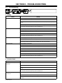
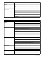
SECTION 8 – TROUBLESHOOTING 28. . . . . . . . . . . . . . . . . . . . . . . . . . . . . . . . . . . . . . . . . . . . . . . . . . . . .
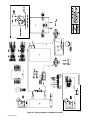
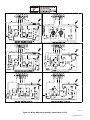
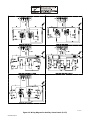
SECTION 9 – ELECTRICAL DIAGRAMS 30. . . . . . . . . . . . . . . . . . . . . . . . . . . . . . . . . . . . . . . . . . . . . . . . .
SECTION 10 – GENERATOR POWER GUIDELINES 35. . . . . . . . . . . . . . . . . . . . . . . . . . . . . . . . . . . . . . .
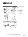
SECTION 11 – STICK WELDING (SMAW) GUIDELINES 42. . . . . . . . . . . . . . . . . . . . . . . . . . . . . . . . . . . .
SECTION 12 – PARTS LIST 50. . . . . . . . . . . . . . . . . . . . . . . . . . . . . . . . . . . . . . . . . . . . . . . . . . . . . . . . . . . .
OPTIONS AND ACCESSORIES
WARRANTY
WARNING
This product, when used
for welding or cutting,
produces fumes or
gases which contain
chemicals known to the
State of California to
cause birth defects and,
in some cases, cancer.
(California Health &
Safety Code Section
25249.5 et seq.)
WARNING
Battery posts, terminals
and related accessories
contain lead and lead
compounds, chemicals
known to the State of
California to cause
cancer and birth defects
or other reproductive
harm. Wash hands after
handling.
Page is loading ...

OM-499 Page 1
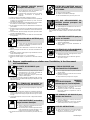
SECTION 1 – SAFETY PRECAUTIONS - READ BEFORE USING
rom _nd_4/02
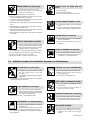
1-1. Symbol Usage
Means Warning! Watch Out! There are possible hazards
with this procedure! The possible hazards are shown in
the adjoining symbols.
Marks a special safety message.
Means “Note”; not safety related.
This group of symbols means Warning! Watch Out! possible
ELECTRIC SHOCK, MOVING PARTS, and HOT PARTS hazards.
Consult symbols and related instructions below for necessary actions
to avoid the hazards.
1-2. Arc Welding Hazards
The symbols shown below are used throughout this manual to
call attention to and identify possible hazards. When you see
the symbol, watch out, and follow the related instructions to
avoid the hazard. The safety information given below is only
a summary of the more complete safety information found in
the Safety Standards listed in Section 1-5. Read and follow all
Safety Standards.
Only qualified persons should install, operate, maintain, and
repair this unit.
During operation, keep everybody, especially children, away.
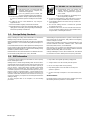
ELECTRIC SHOCK can kill.
Touching live electrical parts can cause fatal shocks
or severe burns. The electrode and work circuit is
electrically live whenever the output is on. The input
power circuit and machine internal circuits are also
live when power is on. In semiautomatic or automatic wire welding, the
wire, wire reel, drive roll housing, and all metal parts touching the
welding wire are electrically live. Incorrectly installed or improperly
grounded equipment is a hazard.
Do not touch live electrical parts.
Wear dry, hole-free insulating gloves and body protection.
Insulate yourself from work and ground using dry insulating mats
or covers big enough to prevent any physical contact with the work
or ground.
Do not use AC output in damp areas, if movement is confined, or if
there is a danger of falling.
Use AC output ONLY if required for the welding process.
If AC output is required, use remote output control if present on
unit.
Disconnect input power or stop engine before installing or
servicing this equipment. Lockout/tagout input power according to
OSHA 29 CFR 1910.147 (see Safety Standards).
Properly install and ground this equipment according to its
Owner’s Manual and national, state, and local codes.
Always verify the supply ground – check and be sure that input
power cord ground wire is properly connected to ground terminal in
disconnect box or that cord plug is connected to a properly
grounded receptacle outlet.
When making input connections, attach proper grounding conduc-
tor first – double-check connections.
Frequently inspect input power cord for damage or bare wiring –
replace cord immediately if damaged – bare wiring can kill.
Turn off all equipment when not in use.
Do not use worn, damaged, undersized, or poorly spliced cables.
Do not drape cables over your body.
If earth grounding of the workpiece is required, ground it directly
with a separate cable.
Do not touch electrode if you are in contact with the work, ground,
or another electrode from a different machine.
Use only well-maintained equipment. Repair or replace damaged
parts at once. Maintain unit according to manual.
Wear a safety harness if working above floor level.
Keep all panels and covers securely in place.
Clamp work cable with good metal-to-metal contact to workpiece
or worktable as near the weld as practical.
Insulate work clamp when not connected to workpiece to prevent
contact with any metal object.
Do not connect more than one electrode or work cable to any
single weld output terminal.
SIGNIFICANT DC VOLTAGE exists in inverters after
stopping engine.
Stop engine on inverter and discharge input capacitors according
to instructions in Maintenance Section before touching any parts.
Arc rays from the welding process produce intense
visible and invisible (ultraviolet and infrared) rays
that can burn eyes and skin. Sparks fly off from the
weld.
ARC RAYS can burn eyes and skin.
Wear a welding helmet fitted with a proper shade of filter to protect
your face and eyes from arc rays and sparks when welding or
watching (see ANSI Z49.1 and Z87.1 listed in Safety Standards).
Wear approved safety glasses with side shields under your
helmet.
Use protective screens or barriers to protect others from flash and
glare; warn others not to watch the arc.
Wear protective clothing made from durable, flame-resistant mate-
rial (wool and leather) and foot protection.
Welding produces fumes and gases. Breathing
these fumes and gases can be hazardous to your
health.
FUMES AND GASES can be hazardous.
Keep your head out of the fumes. Do not breathe the fumes.
If inside, ventilate the area and/or use exhaust at the arc to remove
welding fumes and gases.
If ventilation is poor, use an approved air-supplied respirator.
Read the Material Safety Data Sheets (MSDSs) and the
manufacturer’s instructions for metals, consumables, coatings,
cleaners, and degreasers.
Work in a confined space only if it is well ventilated, or while
wearing an air-supplied respirator. Always have a trained watch-
person nearby. Welding fumes and gases can displace air and
lower the oxygen level causing injury or death. Be sure the breath-
ing air is safe.
Do not weld in locations near degreasing, cleaning, or spraying op-
erations. The heat and rays of the arc can react with vapors to form
highly toxic and irritating gases.
Do not weld on coated metals, such as galvanized, lead, or
cadmium plated steel, unless the coating is removed from the weld
area, the area is well ventilated, and if necessary, while wearing an
air-supplied respirator. The coatings and any metals containing
these elements can give off toxic fumes if welded.

OM-499 Page 2
Welding on closed containers, such as tanks,
drums, or pipes, can cause them to blow up. Sparks
can fly off from the welding arc. The flying sparks, hot
workpiece, and hot equipment can cause fires and
burns. Accidental contact of electrode to metal objects can cause
sparks, explosion, overheating, or fire. Check and be sure the area is
safe before doing any welding.
WELDING can cause fire or explosion.
Protect yourself and others from flying sparks and hot metal.
Do not weld where flying sparks can strike flammable material.
Remove all flammables within 35 ft (10.7 m) of the welding arc. If
this is not possible, tightly cover them with approved covers.
Be alert that welding sparks and hot materials from welding can
easily go through small cracks and openings to adjacent areas.
Watch for fire, and keep a fire extinguisher nearby.
Be aware that welding on a ceiling, floor, bulkhead, or partition can
cause fire on the hidden side.
Do not weld on closed containers such as tanks, drums, or pipes,
unless they are properly prepared according to AWS F4.1 (see
Safety Standards).
Connect work cable to the work as close to the welding area as
practical to prevent welding current from traveling long, possibly
unknown paths and causing electric shock and fire hazards.
Do not use welder to thaw frozen pipes.
Remove stick electrode from holder or cut off welding wire at
contact tip when not in use.
Wear oil-free protective garments such as leather gloves, heavy
shirt, cuffless trousers, high shoes, and a cap.
Remove any combustibles, such as a butane lighter or matches,
from your person before doing any welding.
FLYING METAL can injure eyes.
Welding, chipping, wire brushing, and grinding
cause sparks and flying metal. As welds cool,
they can throw off slag.
Wear approved safety glasses with side
shields even under your welding helmet.
BUILDUP OF GAS can injure or kill.
Shut off shielding gas supply when not in use.
Always ventilate confined spaces or use ap-
proved air-supplied respirator.
HOT PARTS can cause severe burns.
Allow cooling period before maintaining.
Wear protective gloves and clothing when
working on a hot engine.
Do not touch hot engine parts or just-welded
parts bare-handed.
NOISE can damage hearing.
Noise from some processes or equipment can
damage hearing.
Wear approved ear protection if noise level is
high.
MAGNETIC FIELDS can affect pacemakers.
Pacemaker wearers keep away.
Wearers should consult their doctor before
going near arc welding, gouging, or spot
welding operations.
Shielding gas cylinders contain gas under high
pressure. If damaged, a cylinder can explode. Since
gas cylinders are normally part of the welding
process, be sure to treat them carefully.
CYLINDERS can explode if damaged.
Protect compressed gas cylinders from excessive heat, mechani-
cal shocks, slag, open flames, sparks, and arcs.
Install cylinders in an upright position by securing to a stationary
support or cylinder rack to prevent falling or tipping.
Keep cylinders away from any welding or other electrical circuits.
Never drape a welding torch over a gas cylinder.
Never allow a welding electrode to touch any cylinder.
Never weld on a pressurized cylinder – explosion will result.
Use only correct shielding gas cylinders, regulators, hoses, and fit-
tings designed for the specific application; maintain them and
associated parts in good condition.
Turn face away from valve outlet when opening cylinder valve.
Keep protective cap in place over valve except when cylinder is in
use or connected for use.
Read and follow instructions on compressed gas cylinders,
associated equipment, and CGA publication P-1 listed in Safety
Standards.
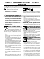
1-3. Engine Hazards
FUEL can cause fire or explosion.
Stop engine and let it cool off before checking or
adding fuel.
Do not add fuel while smoking or if unit is near
any sparks or open flames.
Do not overfill tank – allow room for fuel to expand.
Do not spill fuel. If fuel is spilled, clean up before starting engine.
Dispose of rags in a fireproof container.
STEAM AND HOT COOLANT can burn.
If possible, check coolant level when engine is
cold to avoid scalding.
Always check coolant level at overflow tank, if
present on unit, instead of radiator (unless told
otherwise in maintenance section or engine
manual).
If the engine is warm, checking is needed, and
there is no overflow tank, follow the next two
statements.
Wear safety glasses and gloves and put a rag over radiator cap.
Turn cap slightly and let pressure escape slowly before completely
removing cap.

OM-499 Page 3
MOVING PARTS can cause injury.
Keep away from fans, belts, and rotors.
Keep all doors, panels, covers, and guards
closed and securely in place.
Stop engine before installing or connecting unit.
Have only qualified people remove guards or covers for maint-
enance and troubleshooting as necessary.
To prevent accidental starting during servicing, disconnect
negative (–) battery cable from battery.
Keep hands, hair, loose clothing, and tools away from moving
parts.
Reinstall panels or guards and close doors when servicing is
finished and before starting engine.
Before working on generator, remove spark plugs or injectors to
keep engine from kicking back or starting.
Block flywheel so that it will not turn while working on generator
components.
BATTERY EXPLOSION can BLIND.
Always wear a face shield, rubber gloves, and
protective clothing when working on a battery.
Stop engine before disconnecting or connect-
ing battery cables or servicing battery.
Do not allow tools to cause sparks when working on a battery.
Do not use welder to charge batteries or jump start vehicles.
Observe correct polarity (+ and –) on batteries.
Disconnect negative (–) cable first and connect it last.
BATTERY ACID can BURN SKIN and
EYES.
Do not tip battery.
Replace damaged battery.
Flush eyes and skin immediately with water.
ENGINE EXHAUST GASES can kill.
Use equipment outside in open, well-ventilated
areas.
If used in a closed area, vent engine exhaust
outside and away from any building air intakes.
ENGINE HEAT can cause fire.
Do not locate unit on, over, or near combustible
surfaces or flammables.
Keep exhaust and exhaust pipes way from
flammables.
EXHAUST SPARKS can cause fire.
Do not let engine exhaust sparks cause fire.
Use approved engine exhaust spark arrestor in
required areas – see applicable codes.
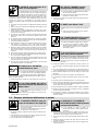
1-4. Additional Symbols For Installation, Operation, And Maintenance
FALLING UNIT can cause injury.
Use lifting eye to lift unit only, NOT running
gear, gas cylinders, trailer, or any other
accessories.
Use equipment of adequate capacity to lift and
support unit.
If using lift forks to move unit, be sure forks are long enough to
extend beyond opposite side of unit.
FLYING SPARKS can cause injury.
Wear a face shield to protect eyes and face.
Shape tungsten electrode only on grinder with
proper guards in a safe location wearing proper
face, hand, and body protection.
Sparks can cause fires — keep flammables away.
OVERHEATING can damage motors.
Turn off or unplug equipment before starting or
stopping engine.
Do not let low voltage and frequency caused by
low engine speed damage electric motors.
Do not connect 50 or 60 Hertz motors to the 100 Hertz receptacle
where applicable.
OVERUSE can cause OVERHEATING.
Allow cooling period; follow rated duty cycle.
Reduce current or reduce duty cycle before
starting to weld again.
Do not block or filter airflow to unit.
STATIC (ESD) can damage PC boards.
Put on grounded wrist strap BEFORE handling
boards or parts.
Use proper static-proof bags and boxes to
store, move, or ship PC boards.
TILTING OF TRAILER can cause injury.
Use tongue jack or blocks to support weight.
Properly install welding generator onto trailer
according to instructions supplied with trailer.
READ INSTRUCTIONS.
Use only genuine MILLER replacement parts.
Perform engine maintenance and service
according to this manual and the engine
manual.

OM-499 Page 4
H.F. RADIATION can cause interference.
High-frequency (H.F.) can interfere with radio
navigation, safety services, computers, and
communications equipment.
Have only qualified persons familiar with
electronic equipment perform this installation.
The user is responsible for having a qualified electrician prompt-
ly correct any interference problem resulting from the installa-
tion.
If notified by the FCC about interference, stop using the
equipment at once.
Have the installation regularly checked and maintained.
Keep high-frequency source doors and panels tightly shut, keep
spark gaps at correct setting, and use grounding and shielding to
minimize the possibility of interference.
ARC WELDING can cause interference.
Electromagnetic energy can interfere with
sensitive electronic equipment such as
computers and computer-driven equipment
such as robots.
Be sure all equipment in the welding area is
electromagnetically compatible.
To reduce possible interference, keep weld cables as short as
possible, close together, and down low, such as on the floor.
Locate welding operation 100 meters from any sensitive elec-
tronic equipment.
Be sure this welding machine is installed and grounded
according to this manual.
If interference still occurs, the user must take extra measures
such as moving the welding machine, using shielded cables,
using line filters, or shielding the work area.
1-5. Principal Safety Standards
Safety in Welding and Cutting, ANSI Standard Z49.1, from American
Welding Society, 550 N.W. LeJeune Rd, Miami FL 33126
Safety and Health Standards, OSHA 29 CFR 1910, from Superinten-
dent of Documents, U.S. Government Printing Office, Washington, D.C.
20402.
Recommended Safe Practices for the Preparation for Welding and Cut-
ting of Containers That Have Held Hazardous Substances, American
Welding Society Standard AWS F4.1, from American Welding Society,
550 N.W. LeJeune Rd, Miami, FL 33126
National Electrical Code, NFPA Standard 70, from National Fire Protec-
tion Association, Batterymarch Park, Quincy, MA 02269.
Safe Handling of Compressed Gases in Cylinders, CGA Pamphlet P-1,
from Compressed Gas Association, 1235 Jefferson Davis Highway,
Suite 501, Arlington, VA 22202.
Code for Safety in Welding and Cutting, CSA Standard W117.2, from
Canadian Standards Association, Standards Sales, 178 Rexdale
Boulevard, Rexdale, Ontario, Canada M9W 1R3.
Safe Practices For Occupation And Educational Eye And Face
Protection, ANSI Standard Z87.1, from American National Standards
Institute, 1430 Broadway, New York, NY 10018.
Cutting And Welding Processes, NFPA Standard 51B, from National
Fire Protection Association, Batterymarch Park, Quincy, MA 02269.
1-6. EMF Information
Considerations About Welding And The Effects Of Low Frequency
Electric And Magnetic Fields
Welding current, as it flows through welding cables, will cause electro-
magnetic fields. There has been and still is some concern about such
fields. However, after examining more than 500 studies spanning 17
years of research, a special blue ribbon committee of the National
Research Council concluded that: “The body of evidence, in the
committee’s judgment, has not demonstrated that exposure to power-
frequency electric and magnetic fields is a human-health hazard.”
However, studies are still going forth and evidence continues to be
examined. Until the final conclusions of the research are reached, you
may wish to minimize your exposure to electromagnetic fields when
welding or cutting.
To reduce magnetic fields in the workplace, use the following
procedures:
1. Keep cables close together by twisting or taping them.
2. Arrange cables to one side and away from the operator.
3. Do not coil or drape cables around your body.
4. Keep welding power source and cables as far away from
operator as practical.
5. Connect work clamp to workpiece as close to the weld as possi-
ble.
About Pacemakers:
Pacemaker wearers consult your doctor first. If cleared by your doctor,
then following the above procedures is recommended.
Page is loading ...
Page is loading ...
Page is loading ...
Page is loading ...

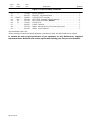
OM-499 Page 9
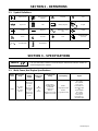
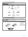
SECTION 2 – DEFINITIONS
2-1. Symbol Definitions
Engine Choke
Read Operator’s
Manual A
Amperes
V
Volts
Engine Oil Fuel Battery (Engine) Engine
Positive Negative
Alternating Current
(AC)
Output
h
Hours
s
Seconds Time
Protective Earth
(Ground)
Circuit Breaker Temperature
SECTION 3 – SPECIFICATIONS
This unit uses either a Kohler or a Honda engine. Differences between models are
noted throughout this manual.
NOTE
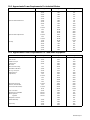
3-1. Weld, Power, And Engine Specifications
Welding
Mode
Weld Output
Range
Rated
Welding
Output
Maximum
Open Circuit
Voltage
Generator Power
Rating
Fuel Capacity Engine
CC/DC
40 – 180 A
(60 Hz)
40 – 160 A
(50 Hz)
180 A, 25 V,
30% Duty
Cycle
130 A, 25 V,
60% Duty
Cycle
100 A, 25 V,
100% Duty
Cycle
80
(60 Hz)
70
(50 Hz)
Single-Phase,
6 kVA/kW (Peak)
5.5 kVA/kW
(Continuous)
50/25 A,
110/220 V AC, 50 Hz
120/240 V AC, 60 Hz
Kohler:
1.8 gal (6.9 L) Tank
Honda:
1.7 gal (6.4 L) Tank
Kohler CS12STG
Air-Cooled,
One-Cylinder,
Four-Cycle,
12 HP (360 CC),
Gasoline Engine
OR
Honda GX390
Air-Cooled,
One-Cylinder,
Four-Cycle,
13 HP (390 CC),
Gasoline Engine

OM-499 Page 10
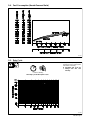
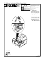
3-2. Dimensions, Weights, And Operating Angles
Dimensions
Height 20-3/4 in (527 mm)
D
Width 22-3/4 in (577 mm)
Depth 31-1/4 in (793 mm) Do not exceed tilt angles or engine could
A 31-1/4 in (793 mm)
B
be damaged or unit could tip.
B 10-1/2 in (268 mm)
Do not move or operate unit where it
could tip.
C 13-45/64 in (348 mm)
D 22-3/4 in (577 mm)
A
E 1-3/4 in (44 mm)
C
F 19-1/2 in (495 mm)
G 13/32 in (10 mm) Dia.
°
°
Weight
G
15
°
°
°
15
°
Kohler: 265 lb (120 kg)
4
Holes
G
15°
15
°
Honda Electric-Start Model:
278 lb (126 kg)
Honda Recoil-Start Model:
253 lb (114 kg)
802 096
Holes
Engine End
F
E
802 524-A
3-3. Fuel Consumption (Kohler-Powered Units)
198 575
50 HZ–AUX
50 HZ–WELD
HIGH IDLE
60 HZ–WELD
60 HZ–AUX
Fuel consumption at low idle
(2000 rpm): 0.2 U.S. gal/hr.

OM-499 Page 11
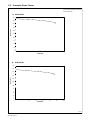
3-4. Fuel Consumption (Honda-Powered Units)
802 122
Continuous Welding
3-5. Duty Cycle
802 093
Duty cycle is the percentage of 10
minutes that unit can weld at rated
load without overheating.
Exceeding duty cycle can
damage unit and void
warranty.
100% Duty Cycle at 100 Amperes CC/DC

OM-499 Page 12
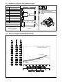
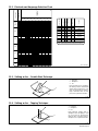
3-6. Generator Power Curves
198 570
The generator power curves show
the ac power available in amperes
at the receptacles.
A. 60 Hz Model
B. 50 Hz Model
0
25
50
75
100
125
150
175
200
225
250
0 5 10 15 20 25 30 35
LOAD AMPS
LOAD VOLTS
0
25
50
75
100
125
150
175
200
225
250
0 5 10 15 20 25 30 35
LOAD AMPS
LOAD VOLTS

OM-499 Page 13
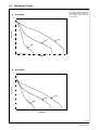
3-7. Volt-Ampere Curves
198 570
The volt-ampere curve shows the
minimum and maximum voltage
and amperage output capabilities of
the welding generator. Curves of all
other settings fall between the
curves shown.
A. 60 Hz Model
B. 50 Hz Model
0
10
20
30
40
50
60
70
80
0 25 50 75 100 125 150 175 200 225 250
LOAD AMPS
LOAD VOLTS
MIN
MID
MAX
0
10
20
30
40
50
60
70
80
0 25 50 75 100 125 150 175 200 225 250
LOAD AMPS
LOAD VOLTS
MIN
MID
MAX

OM-499 Page 14
SECTION 4 – INSTALLATION
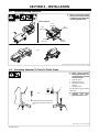
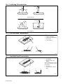
4-1. Installing Welding Generator
install1 10/00*– 802 524-A / Ref. 151 556 / 158 936-A / S-0854
18 in
(460 mm)
18 in
(460 mm)
18 in
(460 mm)
18 in
(460 mm)
18 in
(460 mm)
OR
Movement Airflow Clearance
Location
Always securely fasten welding
generator onto transport vehicle
or trailer and comply with all DOT
and other applicable codes.
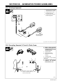
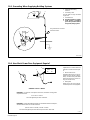
4-2. Grounding Generator To Truck Or Trailer Frame
install1 10/00* – Ref. 151 556 / S-0854
Always ground generator
frame to vehicle frame to pre-
vent electric shock and static
electricity hazards.
1 Generator Base
2 Metal Vehicle Frame
3 Equipment Grounding
Terminal
4 Grounding Cable
Use #10 AWG or larger insulated
copper wire.
If unit does not have GFCI re-
ceptacles, use GFCI-
protected extension cord.
1
2
Electrically bond generator frame to
vehicle frame by metal-to-metal con-
tact.
GND/PE
3
4
2
OR

OM-499 Page 15
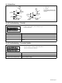
4-3. Grounding Generator When Supplying Building Systems
GND/PE
1 2
Use ground device as
stated in electrical codes.
2
3
800 576-B
1 Equipment Grounding
Terminal
2 Grounding Cable
Use #10 AWG or larger insulated
copper wire.
3 Ground Device
Ground generator to sys-
tem earth ground if supply-
ing power to a premises
(home, shop, farm) wiring
system.
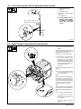
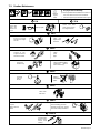
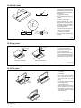
4-4. Engine Prestart Checks (Kohler-Powered Units)
802 511-A
Full
Full
Gasoline
1/2 in
(13 mm)
Follow run-in procedure in engine
manual.
Check all fluids daily. Engine must be
cold and on a level surface. Unit is
shipped with 10W30 engine oil.
Engine stops if oil level gets too low.
This unit has a low oil level shut-
down switch. However, some
conditions may cause engine
damage before the engine shuts
down. Check oil level often and do
not use the oil level shutdown sys-
tem to monitor oil level.
1 Fuel Valve
Open valve by turning lever to vertical
position.
Close fuel valve before moving
unit or carburetor may flood and
make starting difficult.
Fuel
Add fresh fuel before starting engine
the first time (see maintenance label
for specifications). Fill fuel tank up to
1/2 in. (13 mm) from top to allow room
for expansion. Check fuel level on a
cold engine before use each day.
Oil
After fueling, check oil with unit on lev-
el surface. If oil is not up to full mark on
dipstick, add oil (see maintenance la-
bel).
To improve cold weather starting:
Keep battery in good condition.
Store battery in warm area off
concrete surface.
Use correct grade oil for cold
weather.
Open
1
Closed
Closed

OM-499 Page 16
4-5. Engine Prestart Checks (Honda-Powered Units)
802 094-A
Full
Full
Gasoline
1/2 in
(13 mm)
1
Check all fluids daily. Engine must
be cold and on a level surface. Unit
is shipped with 10W30 engine oil.
Engine stops if oil level gets too low.
Follow run-in procedure in en-
gine manual.
1 Fuel Valve
Open valve.
Close fuel valve before moving
unit or carburetor may flood
and make starting difficult.
Fuel
Add fresh fuel before starting
engine the first time (see mainte-
nance label for specifications). Fill
fuel tank up to 1/2 in. (13 mm) from
top to allow room for expansion.
Check fuel level on a cold engine
before use each day.
Oil
After fueling, check oil with unit on
level surface. If oil is not up to full
mark on dipstick, add oil (see main-
tenance label).
To improve cold weather
starting:
Keep battery in good condition.
Store battery in warm area off
concrete surface.
Use correct grade oil for cold
weather.
Open
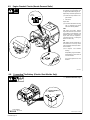
4-6. Connecting The Battery (Electric-Start Models Only)
802 524 / Ref. S-0756-D
3/8, 1/2 in
Tools Needed:
+
–
Connect negative (–)
cable last.
Turn Engine Switch to Off
(electric-start models only).

OM-499 Page 17
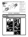
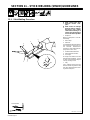
4-7. Connecting To Weld Output Terminals
196 914 / 495 178
1 Positive (+) Weld Output
Terminal
2 Negative (–) Weld Output
Terminal
For Direct Current Electrode Posi-
tive (DCEP), connect work cable to
Negative (–) terminal and electrode
holder to Positive (+) terminal.
For Direct Current Electrode nega-
tive (DCEN), reverse cable con-
nections.
Tools Needed:
3/4 in
12
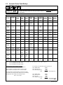
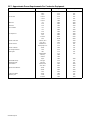
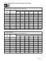
4-8. Selecting Weld Cable Sizes*
Weld Cable Size** and Total Cable (Copper) Length in Weld Circuit
Not Exceeding***
100 ft (30 m) or Less
150 ft
(45 m)
200 ft
(60 m)
250 ft
(70 m)
300 ft
(90 m)
350 ft
(105 m)
400 ft
(120 m)
Weld Output
Terminals
Stop engine before
connecting to weld out-
put terminals.
Do not use worn, dam-
aged, undersized, or
poorly spliced cables.
Welding
Amperes
10 – 60%
Duty
Cycle
60 – 100%
Duty
Cycle
10 – 100% Duty Cycle
100 4 (20) 4 (20) 4 (20) 3 (30) 2 (35) 1 (50) 1/0 (60) 1/0 (60)
150 3 (30) 3 (30) 2 (35) 1 (50) 1/0 (60) 2/0 (70) 3/0 (95) 3/0 (95)
200 3 (30) 2 (35) 1 (50) 1/0 (60) 2/0 (70) 3/0 (95) 4/0 (120) 4/0 (120)
250 2 (35) 1 (50) 1/0 (60) 2/0 (70) 3/0 (95) 4/0 (120)
2 ea. 2/0
(2x70)
2 ea. 2/0
(2x70)
* This chart is a general guideline and may not suit all applications. If cable overheating occurs (normally you can smell it), use next size larger
cable.
**Weld cable size (AWG) is based on either a 4 volts or less drop or a current density of at least 300 circular mils per ampere.
( ) = mm
2
for metric use S-0007-E
***For distances longer than those shown in this guide, call a factory applications representative at 920-735-4505.

OM-499 Page 18
SECTION 5 – OPERATING THE WELDING GENERATOR
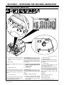
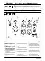
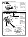
5-1. Controls (Kohler-Powered Units)
802 511-A / 802 0511 / 495 178
6
7
60 Hz
Weld and generator power output stops if
generator overheats or engine speed is
too low.
1 Engine Switch
Use switch to open ignition circuit, and to stop
engine.
2 Throttle Control Lever
Use lever to select engine speed. Use 50 Hz
or 60 Hz position for 50 or 60 Hz generator
power. Use 60 Hz position for maximum weld
output.
3 Choke Control Lever
Use lever to change engine air/fuel mix. Move
lever to right if starting a cold engine. Move le-
ver to left if starting a warm engine.
To Start (Electric): open fuel valve (see Sec-
tion 4-4), move throttle lever to Idle, set choke,
and turn engine switch to Start position. Open
choke as engine warms. If engine does not
crank, use recoil starting procedure following
to start engine.
If engine does not start, let engine
come to a complete stop before at-
tempting restart.
4 Starter Handle
To Start (Recoil): open fuel valve (see Sec-
tion 4-4), move throttle lever to Idle, set choke,
and pull starter handle. Open choke as engine
warms.
To Stop: turn engine switch to Off.
Always close fuel valve after stopping
unit. Moving unit with fuel valve open may
cause carburetor flooding and make
starting difficult.
5 Engine Hour Meter
6 Welding Range Label
Use label to determine correct weld amper-
age based on electrode size, type, and mate-
rial thickness.
7 Current Control
Use control to select weld amperage. Control
may be adjusted while welding.
To Set Current Control: Use label to deter-
mine correct size electrode for material thick-
ness. Select electrode type and set current
control to corresponding amperage range.
Adjust control to obtain desired weld
performance.
EXAMPLE:
Material Thickness: 1/8 to 1/4 in
Electrode Diameter: 1/8
Electrode Type: E-6013
Current Control Setting: 90 – 120 A
1
3
5
2
4
50 Hz

OM-499 Page 19
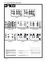
5-2. Controls (Honda-Powered Units) (See Section 5-3)
802 094-A / 802 095 / 495 187
Recoil-Start
Electric-Start
60 Hz
50 Hz
1
3
6
2
1
4
5
7

OM-499 Page 20
5-3. Description Of Controls (Honda-Powered Units) (See Section 5-2)
Weld and generator power output stops if
generator overheats or engine speed is
too low.
1 Engine Switch
On models with recoil-start, use switch to
open ignition circuit, and to stop engine.
On models with electric-start, use switch to
open ignition circuit, and to start and stop en-
gine.
2 Throttle Control Lever
Use lever to select engine speed. Use 50 Hz
or 60 Hz position for generator power. Use 60
Hz position for maximum weld output.
3 Choke Control Lever
Use lever to change engine air/fuel mix. Move
lever to left if starting a cold engine. Move le-
ver to right if starting a warm engine.
4 Starter Handle (Recoil-Start Models
Only)
To Start (Recoil): open fuel valve, turn engine
switch to On, move throttle lever to Idle, set
choke, and pull starter handle. Open choke as
engine warms.
To Start (Electric): open fuel valve, move
throttle lever to Idle, set choke, and turn en-
gine switch to Start position. Open choke as
engine warms.
If engine does not start, let engine
come to a complete stop before at-
tempting restart.
To Stop: turn engine switch to Off.
Always close fuel valve after stopping
unit. Moving unit with fuel valve open may
cause carburetor flooding and make
starting difficult.
5 Engine Hour Meter
6 Welding Range Label
Use label to determine correct weld amper-
age based on electrode size, type, and mate-
rial thickness.
7 Current Control
Use control to select weld amperage. Control
may be adjusted while welding.
To Set Current Control: Use label to deter-
mine correct size electrode for material thick-
ness. Select electrode type and set current
control to corresponding amperage range on
nameplate. Adjust control within selected
range to obtain desired weld performance.
EXAMPLE:
Material Thickness: 1/8 to 1/4 in
Electrode Diameter: 1/8
Electrode Type: E-6013
Current Control Setting: 90 – 120 A
Notes

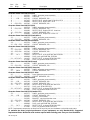
OM-499 Page 21
SECTION 6 – OPERATING AUXILIARY EQUIPMENT
The welding generator provides power while welding and with the Current control
in any position. However, under these conditions equipment connected to the
welding generator may be subject to larger than normal voltage fluctuations. It is
recommended that only lamps be powered under these conditions.
NOTE
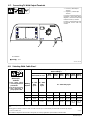
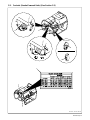
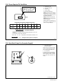
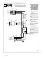
6-1. Generator Power Panel 495 218 (USA)
495 218
1234 5
If unit does not have GFCI recep-
tacles, use GFCI-protected exten-
sion cord.
Power is still present at the 240 volt
receptacle when only one circuit
breaker trips.
Unplug power cord before attempt-
ing to service accessories or tools.
Generator power decreases as weld
current increases.
Set Amperage control at max. for full
generator power.
Place throttle lever in Run position (far
right) for generator power.
1 120 V AC Twistlock Receptacle RC1
RC1 supplies 60 Hz single-phase power at
weld/power speed. Maximum output is 3.5
kVA/kW.
2 120 V 20 A AC Duplex Receptacle
RC2
3 120 V 20 A AC Duplex Receptacle
RC3
RC2 and RC3 supply 60 Hz single-phase
power at weld/power speed. Maximum
output from RC2 or RC3 is 2.4 kVA/kW.
Each receptacle of the duplex can pro-
vide 15A/1800W.
Do not parallel the two 120V duplex
receptacles.
4 Circuit Breaker CB1
CB1 protects RC1 from overload. If CB1
opens, RC1 does not work.
5 Circuit Breakers CB2 And CB3
CB2 protects RC2 and CB3 protects RC3
from overload. If a circuit breaker opens,
the receptacle does not work.
Press button to reset circuit breaker. If
breaker continues to open, contact
Factory Authorized Service Agent.
Combined output of all receptacles limited
to 6 kVA/kW rating of the generator (See
Section 10 – Generator Power Guide-
lines).
EXAMPLE: If 10 A is drawn from each 120
volt duplex receptacle, only 9 A is available
from the 120 V twistlock receptacle.
2 x (120 V x 10 A) + (240 V x 9 A) = 3.5 kVA/
KW.
Page is loading ...
Page is loading ...
Page is loading ...
Page is loading ...
Page is loading ...
Page is loading ...
Page is loading ...
Page is loading ...
Page is loading ...
Page is loading ...
Page is loading ...
Page is loading ...
Page is loading ...
Page is loading ...
Page is loading ...
Page is loading ...
Page is loading ...
Page is loading ...
Page is loading ...
Page is loading ...
Page is loading ...
Page is loading ...
Page is loading ...
Page is loading ...
Page is loading ...
Page is loading ...
Page is loading ...
Page is loading ...
Page is loading ...
Page is loading ...
Page is loading ...
Page is loading ...
Page is loading ...
Page is loading ...
Page is loading ...
-
 1
1
-
 2
2
-
 3
3
-
 4
4
-
 5
5
-
 6
6
-
 7
7
-
 8
8
-
 9
9
-
 10
10
-
 11
11
-
 12
12
-
 13
13
-
 14
14
-
 15
15
-
 16
16
-
 17
17
-
 18
18
-
 19
19
-
 20
20
-
 21
21
-
 22
22
-
 23
23
-
 24
24
-
 25
25
-
 26
26
-
 27
27
-
 28
28
-
 29
29
-
 30
30
-
 31
31
-
 32
32
-
 33
33
-
 34
34
-
 35
35
-
 36
36
-
 37
37
-
 38
38
-
 39
39
-
 40
40
-
 41
41
-
 42
42
-
 43
43
-
 44
44
-
 45
45
-
 46
46
-
 47
47
-
 48
48
-
 49
49
-
 50
50
-
 51
51
-
 52
52
-
 53
53
-
 54
54
-
 55
55
-
 56
56
-
 57
57
-
 58
58
-
 59
59
-
 60
60


Miller Blue Star 6000 Owner's manual
- Category
- Welding System
- Type
- Owner's manual
- This manual is also suitable for
Ask a question and I''ll find the answer in the document
Finding information in a document is now easier with AI
Related papers
-
Miller LC061261 Owner's manual
-
-
-
-
-
Miller Electric LE130162 User manual
-
-
Miller Electric Big Blue 502P Owner's manual
-
-
Other documents
-
HobartWelders CHAMP 2060 KOHLER Owner's manual
-
-
-
Hobart Welding Products CHAMP 2060 KOHLER User manual
-
Hobart CHAMP 1435 Owner's manual
-
-
Hobart Welding Products CHAMP 1435 User manual
-
-
-