Page is loading ...

1
MODELS BTI 120 THRU 400/A
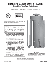
COMMERCIAL GAS, GLASS-LINED, TANK-TYPE WATER HEATER
• INSTALLATION • OPERATION • MAINTENANCE • LIMITED WARRANTY
PLACE THESE INSTRUCTIONS ADJACENT TO HEATER
AND NOTIFY OWNER TO KEEP FOR FUTURE REFERENCE.
PART NO. 195809-000
Printed in U.S.A. 0803 SUPERSEDES PART NO.194780-000
A DIVISION OF A. O. SMITH CORPORATION
McBEE, SOUTH CAROLINA, USA
www.hotwater.com
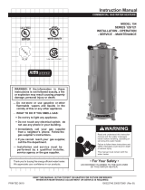
CAUTION
TEXT PRINTED OR OUTLINED IN RED CONTAINS
INFORMATION RELATIVE TO YOUR SAFETY. PLEASE READ
THOROUGHLY BEFORE INSTALLING AND USING THIS
APPLIANCE.
Thank you for buying this energy efficient water heater from
A.O. Smith Water Products Company. We appreciate your
confidence in our products.

2
ROUGH-IN-DIMENSIONS
Model BTI-120 BTI-154 BTI-180 BTI-199 BTI-200 BTI-250 BTI-275 BTI-310 BTI-366 BTI-400
Dim. Inches mm Inches mm Inches mm Inches mm Inches mm Inches mm Inches mm Inches mm Inches mm Inches mm
A 63 1800 70 1778 70 1778 70 1778 72 1829 72 1829 72 1829 73 1854 73 1854 73 1854
B 4 1/4 108 4 1/4 108 4 1/4 108 4 1/4 108 4 1/2 114 4 1/2 114 4 1/2 114 4 1/2 114 4 1/2 114 4 1/2 114
C 59 1/2 1511 66 1/2 1689 66 1/2 1689 66 1/2 1889 70 1778 70 1778 70 1778 72 1829 72 1829 72 1829
D 50 7/8 1292 57 7/8 1470 57 7/8 1470 57 7/8 1470 61 5/8 1565 61 5/8 1565 61 5/8 1565 62 1/2 1588 62 1/2 1588 62 1/2 1588
E 19 11/16 500 19 11/16 500 19 11/16 500 19 11/16 500 20 1/2 521 20 1/2 521 20 1/2 521 20 1/2 521 22 1/2 572 22 1/2 572
F 19 483 19 483 19 483 19 483 21 533 21 533 21 533 21 533 21 533 21 533
G 1/2NPT 1/2NPT 1/2NPT 1/2NPT 1/2NPT 1/2NPT 1/2NPT 3/4NPT 3/4NPT 3/4NPT
(gas inlet)
H 51 7/8 1318 59 1499 59 1499 59 1499 61 1549 61 1549 61 1549 63 1600 63 1600 63 1600
I 5 127 6 152 6 152 6 152 6 152 6 152 6 152 6 152 6 152 6 152
(vent dia)
J 27 3/4 705 27 3/4 705 27 3/4 705 27 3/4 705 27 3/4 705 27 3/4 705 27 3/4 705 27 3/4 705 27 3/4 705 27 3/4 705
K 1 1/2NPT 1 1/2NPT 1 1/2NPT 1 1/2NPT 2NPT 2NPT 2NPT 1 1/2NPT 1 1/2NPT 1 1/2NPT
L 1 1/2NPT 1 1/2NPT 1 1/2NPT 1 1/2NPT 2NPT 2 NPT 2NPT 1 1/2NPT 1 1/2NPT 1 1/2NPT
Appox.
Shipping 400 181 470 213 470 213 470 213 603 274 603 274 603 274 725 329 725 329 725 329
Weight lbs. K.g lbs. K.g lbs. K.g lbs. K.g lbs. K.g lbs. K.g lbs. K.g lbs. K.g lbs. K.g lbs. K.g
STD.
Approx.
Shipping - - - - - - - - 686 311 686 311 686 311 833 378 833 378 833 378
Weight lbs. Kg. lbs. Kg. lbs. Kg. lbs. Kg. lbs. Kg. lbs. Kg.
ASME
FRONT VIEW TOP VIEW
BACK VIEW
TABLE 1. ROUGH-IN-DIMENSIONS
TANK APPROX U.S Gallons/Hr. and Litres/Hr at TEMPERATURE RISE INDICATED
CAPACITY EFF. F° 36F° 40F° 50F° 54F° 60F° 70F° 72F° 80F° 90F° 100F° 108F° 110F° 120F° 126F° 13F° 140F°
Model Btuh KW U.S.Gal. Litres % C° 20C° 22.2C° 27.7C° 30C° 33.3C° 38.8C° 40C° 44.4C° 50C° 55.5C° 60C° 61.1C° 66.6C° 70C° 72.2C° 77.7C°
BTI-120 120,000 71 80 GPH 319 287 230 213 192 164 160 144 128 115 106 105 96 91 88 82
35 269 LPH 1209 1088 870 806 725 622 604 544 484 435 403 396 363 345 335 311
BTI-154 154,000 81 80 GPH 410 369 295 273 246 211 205 184 164 148 137 134 123 117 113 105
45 307 LPH 1551 1396 1117 1034 931 798 776 698 621 559 517 508 465 443 430 399
BTI-180 180,000 81 80 GPH 479 431 345 319 287 246 240 216 192 172 160 157 144 137 133 123
53 307 LPH 1813 1632 1306 1209 1088 933 907 816 725 653 604 593 544 518 502 466
BTI-190 190,000 81 80 GPH 506 455 364 337 303 260 253 228 202 182 169 165 152 144 140 130
56 307 LPH 1914 1723 1378 1276 1148 984 957 861 766 689 638 626 574 547 530 492
BTI-199 199,000 81 80 GPH 530 477 381 353 318 272 265 238 212 191 177 173 159 151 147 136
58 307 LPH 2005 1804 1443 1336 1203 1031 1002 902 802 722 668 656 601 573 555 516
BTI-250 250,000 100 80 GPH 665 599 479 444 399 342 333 299 266 240 222 218 200 190 184 171
73 379 LPH 2519 2267 1813 1679 1511 1295 1259 1133 1007 907 840 824 756 720 697 648
BTI-275 275,000 100 80 GPH 732 659 527 488 439 376 366 329 293 263 244 240 220 209 203 188
81 379 LPH 2770 2493 1995 1847 1662 1425 1385 1247 1108 997 923 907 831 792 767 712
BTI-310 310,000 85 80 GPH 825 743 594 550 495 424 413 371 330 297 275 270 248 236 228 212
91 322 LPH 3123 2811 2249 2082 1874 1606 1561 1405 1249 1124 1041 1022 937 892 865 803
BTI-366 366,000 85 80 GPH 974 877 701 649 584 501 487 438 390 351 325 319 292 278 270 250
107 322 LPH 3687 3318 2655 2458 2212 1896 1844 1659 1475 1327 1229 1207 1106 1053 1021 948
BTI-400 399,000 85 80 GPH 1062 956 765 708 637 546 531 478 425 382 354 348 319 303 294 273
117 322 LPH 4020 3618 2894 2680 2412 2067 2010 1809 1608 1447 1340 1315 1206 1148 1113 1034
TABLE 2. RECOVERY CAPACITIES, based on 80% efficiency
TABLE 3. GAS AND ELECTRICAL CHARACTERISTICS
F
TOP
OUTLET
1 1/2” NPT
TOP
INLET
1 1/2” NPT
Manifold Pressure Maximum Supply Pressure Electrical Characteristics
Model Type of Gas Inches vs. W.C. kPa Inches W.C. kPa Volts/Hz Amperes
Natrual 3.5 0.87 14 3.48 120/60 < 5
Propane 10 2.49 14 3.48 120/60 < 5
BTI 120-400
Minimum Supply Pressure, Natural Gas: 4.5 inches W.C. (1.12kPa)
Minimum Supply Pressure, Propane Gas: 11.0 inches W.C. (1.74kPa)
Minimum Pressures must be maintained under both load and no load (static and dynamic) conditions.

3
TABLE OF CONTENTS
ROUGH-IN-DIMENSIONS ................................................ 2
FOREWORD ..................................................................... 3
GENERAL SAFETY INFORMATION .................................. 4
Precautions .................................................................. 4
Grounding Instructions ................................................. 4
Chemical Vapor Corrosion ........................................... 4
Improper Combustion .................................................. 4
Liquid Petroleum Models ............................................. 4
Extended non-use ........................................................ 4
Insulation Blankets ....................................................... 4-5
High Altitude Installation ............................................... 5
FEATURES ....................................................................... 5
The Eliminator (Self-Cleaning System) ....................... 5
High Limit Switch .......................................................... 5
Electronic Ignition Control ............................................ 5
Exhaust Inducer (Blower Assy.) .................................... 6
Circulating Pump .......................................................... 6
Dishwashing Machine Requirement ........................... 6
INSTALLATION INSTRUCTIONS ...................................... 6
Required Ability ............................................................. 6
Uncrating ...................................................................... 6
Locating The Heater ..................................................... 6-7
Levelling ....................................................................... 7
Clearances ................................................................... 7
Hard Water ................................................................... 7
Air Requirements ......................................................... 7-8
Venting .......................................................................... 8
Multiple Heater Manifold ............................................... 8
Technical Data Venting ................................................. 9-10
Water Line Connections .............................................. 11
Water (Potable) Heating and Space Heating ............... 11
Thermometers (Not Supplied) ..................................... 11
Relief Valve ................................................................... 11
Gas Piping .................................................................... 11-12
Purging ......................................................................... 12
Gas Pressure Regulator .............................................. 12
Heater Wiring ................................................................ 13
INSTALLATION DIAGRAMS ............................................... 14-20
MANIFOLDS ...................................................................... 21
OPERATION ...................................................................... 22
General ......................................................................... 22
SEQUENCE OF OPERATION ........................................... 23
Lighting and Operation................................................. 24
Water Temperature Control .......................................... 25
PREVENTIVE MAINTENANCE ......................................... 25
Check The Ignitor Assembly ........................................ 25
Ignitor Assembly ........................................................... 25
Main Burner .................................................................. 25-26
Gas Valves .................................................................... 26
Checking The Input ...................................................... 26
Venting System ............................................................. 26
Remote Storage Tank Temperature Control ................ 26
Relief Valve ................................................................... 26-27
Hot Water Odor ............................................................. 27
Anode Rod Inspection .................................................. 27
Flushing........................................................................ 27
Draining ........................................................................ 27
Recommended Procedure For Periodic
Removal of Lime Deposits From Tank Type
Commercial Water Heaters ......................................... 27-28
Deliming Solvents ........................................................ 28
Tank Cleanout Procedures .......................................... 28-29
Ignition Module System ................................................ 29
System Diagnostics ..................................................... 29
SERVICE .......................................................................... 29
Electrical Servicing ....................................................... 29
Replacement Parts ...................................................... 29
Sequence of Operation Flow Chart .............................. 30
Operational Checklist ................................................... 31
Limited Warranty .......................................................... 32
Page
Page
FOREWORD
These designs comply with ANSI Z21.10.3 as an automatic
circulating or automatic storage tank type water heater.
BTI 366 and BTI 400 also comply with ANSI Z21.10.3 as an
automatic instantaneous type heater.
Detailed installation diagrams are found in this manual. These
diagrams will serve to provide the installer with a reference for
the materials and methods of piping necessary. It is highly
essential that all water, gas piping and wiring be installed as
shown on the diagrams.
Particular attention should be given to the installation of
thermometers at the locations indicated on the diagrams as
these are necessary for checking the proper functioning of the
heater.
The heater is designed to operate on natural or propane gases.
HOWEVER, MAKE SURE the gas on which the heater will operate
is the same as that specified on the heater model and rating
plate.
These heaters may be installed on combustible floors.
In addition to these instructions, the equipment shall be installed
in accordance with those installation regulations in force in the
local area where the installation is to be made. These shall be
carefully followed in all cases. Authorities having jurisdiction
should be consulted before installations are made.
The installation must conform to these instructions and the local
code authority having jurisdiction. In the absence of local codes,
the installation must comply with the latest editions of the
National Fuel Gas Code, ANSI Z223.1/NFPA 54 and the National
Electrical Code, NFPA 70, documents are available from the
National Fire Protection Association, 1 Batterymarch Park, Quincy,
MA 02269.

4
GENERAL SAFETY
INFORMATION
PRECAUTIONS
DO NOT USE THIS APPLIANCE IF ANY PART HAS BEEN UNDER
WATER. Immediately call a qualified service technician to inspect
the appliance and to replace any part of the control system and
any gas control which has been under water.
IF THE UNIT IS EXPOSED TO THE FOLLOWING, DO NOT
OPERATE HEATER UNTIL ALL CORRECTIVE STEPS HAVE
BEEN MADE BY A QUALIFIED SERVICEMAN.
1. EXTERNAL FIRE.
2. DAMAGE.
3. FIRING WITHOUT WATER.
4. SOOTING
GROUNDING INSTRUCTIONS
This water heater must be grounded in accordance with the
National Electric Code and/or local codes. These must be
followed in all cases.
This water heater must be connected to a grounded metal,
permanent wiring system; or an equipment grounding conductor
must be run with the circuit conductors and connected to the
equipment grounding terminal or lead on the water heater, see
Figure 9.
CHEMICAL VAPOR CORROSION
WARNING
CORROSION OF THE FLUEWAYS AND VENT SYSTEM MAY
OCCUR IF AIR FOR COMBUSTION CONTAINS CERTAIN
CHEMICAL VAPORS. SUCH CORROSION MAY RESULT IN
FAILURE AND RISK OF ASPHYXIATION.
Spray can propellants, cleaning solvents, refrigerator and air
conditioning refrigerants, swimming pool chemicals, calcium
and sodium chloride (water softener salt), waxes, and process
chemicals and typical compounds which are potentially
corrosive. Do not store products of this sort near the heater.
Also, air which is brought in contact with a the heater should not
contain any of these chemicals. If necessary, uncontaminated
air should be obtained from remote or outside sources. The
limited warranty is voided when failure of water heater is due to
a corrosive atmosphere. (Refer to the limited warranty for
complete terms and conditions.
IMPROPER COMBUSTION
WARNING
ATTIC AND/OR EXHAUST FANS OPERATING ON THE
PREMISES WITH A WATER HEATER CAN RESULT IN CARBON
MONOXIDE POISONING AND DEATH.
OPERATION OF THESE FANS CAN PRODUCE A NEGATIVE
DRAFT IN THE AREA OF THE WATER HEATER PREVENTING
THE PRODUCTS OF COMBUSTION FROM EXHAUSTING
THROUGH THE CHIMNEY OR VENT PIPE.
The venting of the water heater should be inspected by a qualified
service technician at the time of installation and periodically
thereafter to ensure a down-draft condition does not exist.
DO NOT OBSTRUCT THE FLOW OF COMBUSTION AND
VENTILATING AIR. ADEQUATE AIR FOR COMBUSTION AND
VENTILATION MUST BE PROVIDED FOR SAFE OPERATION.
LIQUID PETROLEUM MODELS
Water heaters for propane or liquefied petroleum gas (LPG) are
different from natural gas models. A natural gas heater will not
function safely on LP gas and no attempt should be made to
convert a heater from natural gas to LP gas.
LP gas must be used with great caution. It is highly explosive
and heavier than air. It collects first in the low areas making its
odor difficult to detect at nose level. If LP gas is present or even
suspected, do not attempt to find the cause yourself. Go to a
neighbor's house, leaving your doors open to ventilate the house,
then call your gas supplier or service agent. Keep area clear
until a service call has been made.
At times you may not be able to smell an LP gas leak. One
cause is odor fade, which is a loss of the chemical odorant that
gives LP gas its distinctive smell. Another cause can be your
physical condition, such as having a cold or diminishing sense
of smell with age. For these reasons, the use of a propane gas
detector is recommended.
IF YOU EXPERIENCE AN OUT-OF-GAS SITUATION, DO NOT
TRY TO RELIGHT APPLIANCES YOURSELF. Only trained LP
professionals should conduct the required safety checks in
accordance with industry standards.
EXTENDED NON-USE PERIODS
WARNING
HYDROGEN GAS CAN BE PRODUCED IN A HOT WATER
SYSTEM SERVED BY THIS HEATER THAT HAS NOT BEEN USED
FOR A LONG PERIOD OF TIME (GENERALLY TWO WEEKS OR
MORE). HYDROGEN GAS IS EXTREMELY FLAMMABLE. To
reduce the risk of injury under these conditions, it is
recommended that the hot water faucet be opened for several
minutes at the kitchen sink before using any electrical appliance
connected to the hot water system. If hydrogen is present, there
will probably be an unusual sound such as air escaping through
the pipe as the water begins to flow. THERE SHOULD BE NO
SMOKING OR OPEN FLAME NEAR THE FAUCET AT THE TIME
IT IS OPEN.
INSULATION BLANKETS
Insulation blankets available to the general public for external
use on gas water heaters are not approved for use on your
A.O. Smith water heater. The purpose of an insulation blanket is
to reduce the standby heat loss encountered with storage tank
water heaters. Your A.O. Smith water heater meets or exceeds
the ASHRAE/IES 90.1b-1992 standards with respect to insulation
and standby loss requirement making an insulation blanket
unnecessary.
WARNING
Should you choose to apply an insulation blanket to this heater,
you should follow these instructions. Failure to follow these
instructions can result in fire, asphyxiation , serious personal
injury or death.

5
• Do not apply insulation to the top of the water heater, as this
will interfere with safe operation of drafthood.
•
Do not cover the temperature & pressure relief valve.
•
Do not cover the instruction manual. Keep it on the side of the
water heater or nearby for future reference.
• Do obtain new labels from A.O. Smith for placement on the
blanket directly over the existing labels.
HIGH ALTITUDE INSTALLATIONS
WARNING
INSTALLATIONS ABOVE 2000 FEET (610 METERS) REQUIRE
REPLACEMENT OF THE BURNER ORIFICE IN ACCORDANCE
WITH SECTION 8.1.2 OF THE NATIONAL FUEL GAS CODE
(ANSI Z223.1). FAILURE TO REPLACE THE ORIFICE WILL
RESULT IN IMPROPER AND INEFFICIENT OPERATION OF THE
APPLIANCE RESULTING IN THE PRODUCTION OF
INCREASED LEVELS OF CARBON MONOXIDE GAS IN EXCESS
OF SAFE LIMITS WHICH COULD RESULT IN SERIOUS
PERSONAL INJURY OR DEATH.
You should contact your gas supplier for any specific changes
which may be required in your area.
As elevation above sea level is increased, there is less oxygen
per cubic foot of air. Therefore, the heater input rate should be
reduced at high altitudes for satisfactory operation with the
reduced oxygen supply. Failure to make this reduction would
result in an overfiring of the heater causing sooting, poor
combustion and/or unsatisfactory heater performance.
REQUIREMENTS
Ratings specified by manufacturers for most appliances apply
for elevations up to 2000 feet (610m). For elevations above
2000 feet (610m), ratings must be reduced at the rate of 4% for
each 1000 feet (305M) above sea level. For example, if a heater
is rated at 120,000 Btuh (35kW) at sea level, to rate the heater at
4000 feet (1220m), you subtract 4 (once for each thousand feet)
x.04 (4% input reduction) x 120,000 Btuh (original rating) from
the original rating. Therefore, to calculate the input rating at
4,000 feet: 4 x .04 x 120,000 =19,200 Btuh, 120,000 - 19,200 =
100,800 Btuh (30kW). At 6000 feet the correct input rating should
be 91,200 Btuh (27kW).
The input reduction is primarily achieved by reducing the size of
the main burner orifices. To do this, the main burner orifices
require replacement with orifices sized for the particular
installation elevation. Correct orifice sizing and parts may be
obtained from A.O. Smith Water Products Company. When
ordering, be sure to state the model number and the altitude of
the location where the water heater is being installed.
Upon completion of derating of the heater, adjustment to the gas
pressure regulator may be required. See CHECKING THE
INPUT section in this manual for inlet and manifold pressure
requirements.
Also due to the input rating reduction required at high altitudes,
the output rating of the appliance is also reduced and should be
compensated for in the sizing of the equipment for application.
FEATURES
THE ELIMINATOR (SELF-CLEANING SYSTEM)
These units include The Eliminator (Self-Cleaning System)
installed in the front water inlet, See Figure 2. The Eliminator
must be oriented correctly for proper function. There is a marked
range on the pipe nipple portion of the Eliminator, that must be
aligned with the top of the inlet spud. A label above the jacket
hole has an arrow that will point to the marked portion of the pipe
nipple if the orientation is correct. If the arrow does not point
within the marked range on the pipe nipple, adjust the pipe
nipple to correct. A pipe union is supplied with the Eliminator to
reduce the probability of misaligning the Eliminator accidentally
while tightening the connection to the inlet water supply line.
Improper orientation of the Eliminator can cause poor
performance of the heater and can significantly reduce outlet
water temperatures during heavy draws.
Note: The inlet tube may have 1, 3 or 7 cross tubes.
FIGURE 2
For proper function, the Eliminator must be oriented correctly.
There is a marked range on the pipe nipple that must be aligned
with the top of the inlet spud (check for label on the appliance) to
assure proper operation. Please check to confirm that the
marked range is in alignment with the top of the spud. A pipe
union is supplied with the Eliminator to help eliminate the
possibility of changing the orientation by accidentally
overtightening the inlet supply. Improper orientation of the
Eliminator may cause temperature buildup issues or spells of
colder than usual water temperatures.
HIGH LIMIT SWITCH
The digital thermostat (Fig. 3) contains the high limit (energy
cutoff) sensor. The high limit switch interrupts main burner gas
flow should the water temperature reach 203°F (95°C).
In the event of high limit switch operation, the appliance cannot
be restarted unless the water temperature is reduced to
approximately 120°F (49°C). The high limit reset button on the
front of the control then needs to be depressed.
Continued manual resetting of high limit control, preceded by
higher than usual water temperature is evidence of high limit
switch operation. The following is a possible reason for high
limit switch operation.
A malfunction in the thermostatic controls would allow the gas
valve to remain open causing water temperature to exceed the
thermostat setting. The water temperature would continue to
rise until high limit switch operation.
Contact your dealer or service agent if continued high limit switch
operation occurs.
FIGURE 3 - DIGITAL THERMOSTAT

6
ELECTRONIC IGNITION CONTROL
Each heater is equipped with a ignition module. The solid state
ignition control (Fig. 4), ignites the main burner by utilizing a
silicone nitride ignitor. The silicone nitride ignitor shuts off during
the heating cycle and the main burner flame is sensed through
a remote flame sensor integral to the silicone nitride ignitor
assembly. The ignition control will try to ignite the main burner
three times before lockout. Then it waits one hour before trying
again to ignite the main burners. This is a continuous cycle.
FIGURE 4 - IGNITION CONTROL BOARD
EXHAUST INDUCER (BLOWER ASSY.)
All units are equipped with a exhaust inducer (Fig. 5). The inducer
assists in drawing in fresh air to the unit for combustion and
then assists in dispensing the combustion by-products into the
venting leading outside.
The exhaust inducer is equipped with a gravity controlled damper
to reduce the amount of heat loss through the flue, improving
efficiency.
FIGURE 5 - EXHAUST INDUCER
CIRCULATING PUMP
A circulating pump is used when a system requires a circulating
loop or there is a storage tank used in conjunction with the
heater. Refer to the piping diagrams at rear of manual for electrical
hookup information and install in accordance with the latest
version of the National Electric Code ANSI/NFPA No. 70.
Only all bronze circulators are used with commercial water
heaters.
Although circulators are oiled and operated by the manufacturer
some circulators must be oiled again before operating. Please
refer to manufacturer’s instructions.
DISHWASHING MACHINE REQUIREMENT
These appliances meet the National Sanitation Foundation
Standard for sanitary installations when used with the following
leg kits, Part No’s. 6570-0 and 6570-7.
All dishwashing machines meeting the National Sanitation
Foundation requirements are designed to operate with water
flow pressures between 15 (1 bar) and 25 psi (1.7 bars). Flow
pressures above 25 psi (1.7 bars), or below 15 psi (1 bar), will
result in improperly sanitized dishes. Where pressures are
high, a water pressure reducing or flow regulating control valve
should be used in 180
0
F (82°C) line to the dishwashing machine,
and should be adjusted to deliver water between these limits.
The National Sanitation Foundation also recommends
circulation of 180
0
F(82°C) water. Where this is done, the
circulation should be very gentle so that it does not cause any
unnecessary turbulence inside the water heater. The circulation
should be just enough to provide 180
0
F (82°C) water at the point
of take-off to the dishwashing machine. Adjust flow by means of
the plug cock in the circulating line.
INSTALLATION INSTRUCTIONS
REQUIRED ABILITY
INSTALLATION OR SERVICE OF THIS WATER HEATER
REQUIRES ABILITY EQUIVALENT TO THAT OF A LICENSED
TRADESMAN IN THE FIELD INVOLVED. PLUMBING, AIR
SUPPLY, VENTING, GAS SUPPLY AND ELECTRICAL WORK ARE
REQUIRED.
WARNING
FAILURE TO FOLLOW THESE INSTRUCTIONS CAN RESULT
IN SERIOUS PERSONAL INJURY OR DEATH.
UNCRATING
The heater is shipped with the inducer already installed. The
wiring conduit runs from the thermostat to the inducer. Before
turning unit on, check to make sure the wiring conduit is securely
plugged into the inducer.
LOCATING THE HEATER
WARNING
THERE IS A RISK IN USING FUEL BURNING APPLIANCES
SUCH AS GAS WATER HEATERS IN ROOMS, GARAGES OR
OTHER AREAS WHERE GASOLINE, OTHER FLAMMABLE
LIQUIDS OR ENGINE DRIVEN EQUIPMENT OR VEHICLES ARE
STORED, OPERATED OR REPAIRED. FLAMMABLE VAPORS
ARE HEAVY AND TRAVEL ALONG THE FLOOR AND MAY BE
IGNITED BY THE HEATER’S PILOT OR MAIN BURNER FLAMES
CAUSING FIRE OR EXPLOSION. SOME LOCAL CODES PERMIT
OPERATION OF GAS APPLIANCES IN SUCH AREAS IF THEY
ARE INSTALLED 18” OR MORE ABOVE THE FLOOR. THIS MAY
REDUCE THE RISK IF LOCATION IN SUCH AN AREA CANNOT
BE AVOIDED.
DO NOT INSTALL THIS WATER HEATER DIRECTLY ON A
CARPETED FLOOR. A FIRE HAZARD MAY RESULT. Instead the
water heater must be placed on a metal or wood panel extending
beyond the full width and depth by at least 3 inches in any direction.
If the heater is installed in a carpeted alcove, the entire floor
shall be covered by the panel. Also, see the DRAINING
requirements in MAINTENANCE Section.
THE HEATER SHALL BE LOCATED OR PROTECTED SO IT IS
NOT SUBJECT TO PHYSICAL DAMAGE BY A MOVING VEHICLE.

7
WARNING
FLAMMABLE ITEMS, PRESSURIZED CONTAINERS OR ANY
OTHER POTENTIAL FIRE HAZARDOUS ARTICLES MUST
NEVER BE PLACED ON OR ADJACENT TO THE HEATER. OPEN
CONTAINERS OR FLAMMABLE MATERIAL SHOULD NOT BE
STORED OR USED IN THE SAME ROOM WITH THE HEATER.
When installing the heater, consideration must be given to proper
location. Location selected should be as close to the stack or
chimney as practicable, with adequate air supply and as
centralized with the piping system as possible.
THE HEATER MUST NOT BE LOCATED IN AN AREA WHERE IT
WILL BE SUBJECT TO FREEZING.
LOCATE IT NEAR A FLOOR DRAIN. THE HEATER SHOULD BE
LOCATED IN AN AREA WHERE LEAKAGE FROM THE HEATER
OR CONNECTIONS WILL NOT RESULT IN DAMAGE TO THE
ADJACENT AREA OR TO LOWER FLOORS OF THE
STRUCTURE.
WHEN SUCH LOCATIONS CANNOT BE AVOIDED, A SUITABLE
DRAIN PAN SHOULD BE INSTALLED UNDER THE HEATER.
Such pans should be fabricated with sides at least 2" (51mm)
deep, with length and width at least 2" (51mm) greater than the
diameter of the heater and must be piped to an adequate drain.
The pan must not restrict combustion air flow.
For appliance installation locations with elevations above
2000 feet (610m), refer to HIGH ALTITUDE INSTALLATIONS
section of this manual for input reduction procedure.
LEVELING
If the unit is not level, insert the bolts which were used in crating
into the legs to correct this condition.
CLEARANCES
These heaters are approved for installation on combustible
flooring in an alcove when the minimum clearance from any
combustion construction are followed as indicated in figure 6
and Table 4.
Model BTI 366 is approved for installation on non-cumbustible
flooring or combustible flooring with leg kit part no. 6570.
In all installations the minimum combustible clearances from
vent piping shall be 6" (152mm). Vent piping passing through a
combustible wall or ceiling must be a continuous run (no joints)
and retain the 6" (152mm) clearance unless an approved
reducing thimble is used.
A service clearance of 24" (610mm) should be maintained from
serviceable parts, such as relief valves, flue baffles, thermostats,
cleanout openings or drain valves.
The units are approved for installation with side, rear and ceiling
clearances as indicated below:
MINIMUM CLEARANCES TO COMBUSTIBLES
MODEL ”A” ”B” ”C” ”D”
RIGHT SIDE LEFT SIDE BACK CEILING
BTI-120 2” (51mm) 2” (51mm) 2” (51mm) 12” (305mm)
BTI-154 1” (25.4mm) 1” (25.4mm) 1” (25.4mm) 12” (305mm)
BTI-180 3” (76mm) 3” (76mm) 3” (76mm) 12” (305mm)
BTI-199 3” (76mm) 3” (76mm) 3” (76mm) 12” (305mm)
BTI-200/A 2” (51mm) 2” (51mm) 2” (51mm) 12” (305mm)
BTI-250/A 2” (51mm) 2” (51mm) 2” (51mm) 12” (305mm)
BTI-275/A 2” (51mm) 2” (51mm) 2” (51mm) 12” (305mm)
BTI-310/A 3” (76mm) 3” (76mm) 3” (76mm) 12” (305mm)
BTI-366/A 3” (76mm) 3” (76mm) 3” (76mm) 12” (305mm)
BTI-400/A 3” (76mm) 3” (76mm) 3” (76mm) 12” (305mm)
TABLE 4
CLEARANCES TO NONCOMBUSTION CONSTRUCTION
MODEL ”A” ”B” ”C” ”D”
RIGHT SIDE LEFT SIDE BACK CEILING
BTI-120 0 0 0 12” (305mm)
BTI-154 0 0 0 12” (305mm)
BTI-180 3” (76mm) 3” (76mm) 3” (76mm) 12” (305mm)
BTI-199 3” (76mm) 3” (76mm) 3” (76mm) 12” (305mm)
BTI-200/A 0 0 0 12” (305mm)
BTI-250/A 0 0 0 12” (305mm)
BTI-275/A 0 0 0 12” (305mm)
BTI-310/A 0 0 0 12” (305mm)
BTI-366/A 0 0 0 12” (305mm)
BTI-400/A 3” (76mm) 3” (76mm) 3” (76mm) 12” (305mm)
TABLE 5
HARD WATER
Where hard water conditions exist, water softening or the
threshold type of water treatment is recommended. This will
protect the dishwashers, coffee urns, water heaters, water piping
and other equipment.
See MAINTENANCE section for details of tank cleanout
procedure.
AIR REQUIREMENTS
REFER TO THE LATEST EDITION OF THE "NATIONAL FUEL
GAS CODE" ANSI Z223.1/NFPA 54.
KEEP APPLIANCE AREA CLEAR AND FREE OF COMBUSTIBLE
MATERIALS, GASOLINE AND OTHER FLAMMABLES, VAPORS
AND LIQUIDS.
DO NOT OBSTRUCT THE FLOW OF COMBUSTION OR
VENTILATING AIR.
WARNING
FOR SAFE OPERATION PROVIDE ADEQUATE AIR FOR
COMBUSTION AND VENTILATION. AN INSUFFICIENT SUPPLY
OF AIR WILL CAUSE RECIRCULATION OF COMBUSTION
PRODUCTS RESULTING IN AIR CONTAMINATION THAT MAY
BE HAZARDOUS TO LIFE. SUCH A CONDITION OFTEN WILL
RESULT IN A YELLOW, LUMINOUS BURNER FLAME, CAUSING
CARBONING OR SOOTING OF THE COMBUSTION CHAMBER,
BURNERS AND FLUE TUBES AND CREATES A RISK OF
ASPHYXIATION.
Where an exhaust fan is supplied in the same room with a
heater, sufficient openings for air must be provided in the walls.
UNDERSIZED OPENINGS WILL CAUSE AIR TO BE DRAWN
INTO THE ROOM THROUGH THE CHIMNEY, CAUSING POOR
COMBUSTION. SOOTING MAY RESULT IN SERIOUS DAMAGE
TO THE HEATER AND RISK OF FIRE OR EXPLOSION.
UNCONFINED SPACE
In buildings of conventional frame, brick, or stone construction,
unconfined spaces may provide adequate air for combustion,
ventilation and draft hood dilution.
If the unconfined space is within a building of tight construction
(buildings using the following construction: weather stripping,
heavy insulation, caulking, vapor barrier, etc.), air for combustion,
ventilation and draft hood dilution must be obtained from
outdoors. The installation instructions for confined spaces in
tightly constructed buildings must be followed to ensure
adequate air supply.
CONFINED SPACE
When drawing combustion and dilution air from inside a
conventionally constructed building to a confined space, such a
space shall be provided with two permanent openings, ONE IN
OR WITHIN 12 INCHES (30.5cm) OF THE ENCLOSURE TOP

8
AND ONE IN OR WITHIN 12 INCHES (30.5cm) OF THE
ENCLOSURE BOTTOM. Each opening shall have a free area of
at least one square inch per 1000 Btuh (2,225mm
2
/kW)of the
total input of all appliances in the enclosure, but not less than
100 square inches (645 square cm).
If the confined space is within a building of tight construction, air
for combustion, ventilation, and drafthood dilution must be
obtained from outdoors. When directly communicating with the
outdoors or communicating with the outdoors through vertical
ducts, two permanent openings, located in the above manner,
shall be provided. Each opening shall have a free area of not
less than one square inch per 4000 Btuh (550mm
2
/kW) of the
total input of all appliances in the enclosure. If horizontal ducts
are used, each opening shall have a free area of not less than
one square inch per 2000 Btuh (1102mm
2
/kW) of the total input
of all appliances in the enclosure.
VENTING
WARNING
THE INSTRUCTIONS IN THIS SECTION ON VENTING MUST
BE FOLLOWED TO AVOID CHOKED COMBUSTION OR
RECIRCULATION OF FLUE GASES. SUCH CONDITIONS
CAUSE SOOTING OR RISKS OF FIRE AND ASPHYXIATION.
Heater must be protected from freezing downdrafts.
Remove all soot or other obstructions from the chimney that will
retard a free draft.
Type B venting is recommended with these heaters. For typical
venting application see TECHNICAL DATA VENTING on pages 9
and 10.
This water heater must be vented in compliance with all local
codes, the current revision of the National Fuel Gas Code
(ANSI-Z223.1) and with the Category I Venting Tables.
If any part of the vent system are exposed to ambient
temperatures below 40°F (5°C) it must be insulated to prevent
condensation.
The following steps shall be followed with each appliance
connected to the venting system placed in operation, while any
other appliances connected to the venting system are not in
operation.
1. Seal any unused openings in the venting system.
2. Inspect the venting system for proper size and horizontal pitch,
as required in the National Fuel Gas Code, ANSI Z223.1.
Determine that there is no blockage or restriction, leakage,
corrosion and other deficiencies which could cause an unsafe
condition.
3. So far as is practical, close all building doors and windows
and all doors between the space in which the water heater(s)
connected to the venting system are located and other spaces
of the building. Turn on all appliances not connected to the
venting system. Turn on all exhaust fans, such as range
hoods and bathroom exhausts, so they shall operate at
maximum speed. Close fireplace dampers.
4. Follow the lighting instruction. Place the water heater being
inspected in operation. Adjust thermostat so appliance shall
operate continuously.
5. After it has been determined that each appliance connected
to the venting system properly vents when tested as outlined
above, return doors, windows, exhaust fans, fireplace
dampers and any other gas burning appliance to their
previous conditions of use.
6. If improper venting is observed during any of the above tests,
the venting system must be corrected.
WARNING
FAILURE TO CORRECT BACK DRAFTS MAY CAUSE AIR
CONTAMINATION AND UNSAFE CONDITIONS.
• If the back draft cannot be corrected by the normal method or
if a suitable draft cannot be obtained, a blower type flue gas
exhauster must be employed to assure proper venting and
correct combustion.
• Do not connect the heater to a common vent or chimney with
solid fuel burning equipment. This practice is prohibited by
many local building codes as is the practice of venting gas
fired equipment to the duct work of ventilation systems.
FIGURE 7
• Where a separate vent connection is not available and the
vent pipe from the heater must be connected to a common
vent with an oil burning furnace, the vent pipe should enter
the smaller common vent or chimney at a point above the
large vent pipe.
MULTIPLE HEATER MANIFOLD
Figure 8 and tables on pages 9 and 10 should be used for
horizontally manifolding two or more heaters.
FIGURE 8
ILLUSTRATION OF MINIMUM COMBUSTIBLE CLEARANCES IN AN ALCOVE - FIGURE 6

9
TYPE B GAS VENT
Multiple Gas Fired Tank-Type Heaters
When venting multiple tank type heaters using Type B
vent pipe, follow the installation diagram (figure 4) and
tables below which give sizing and data based upon
NFPA 54/ANSI Z223. 1992.
TECHNICAL DATA VENTING
MODEL BTI-120
Input: 120,000 Btu/hr Total Vent Height (Feet)
Vent Connector Size: 5 inches 6 8 10 15 20 30 50 100
Input Btu/hr Rise Vent Connector Diameter (Inches)
120,000 1 Ft. 6 6 5 5 5 5 5 5
120,000 2 Ft. 5 5 5 5 5 5 5 5
120,000 3 Ft. 5 5 5 5 5 5 5 5
Number of Combined Input
BTI 120 Heaters in Thousands of Btu/hr Manifold and Common Vent Diameter (Inches)
2 240,000 7 7 6 6 6 6 6 6
3 360,000 8 8 7 7 7 6 6 6
4 480,000 9 9 9 8 8 7 7 6
MODEL BTI-154
Input: 154,000 Btu/hr Total Vent Height (Feet)
Vent Connector Size: 6 inches 6 8 10 15 20 30 50 100
Input Btu/hr Rise Vent Connector Diameter (Inches)
154,000 1 Ft. 6 6 6 6 6 6 6 6
154,000 2 Ft. 6 6 6 6 6 6 6 6
154,000 3 Ft. 6 6 6 6 6 6 6 6
Number of Combined Input
BTI 154 Heaters in Thousands of Btu/hr Manifold and Common Vent Diameter (Inches)
2 308,000 7 7 6 6 6 6 6 6
3 462,000 8 8 7 7 7 6 6 6
4 616,000 9 9 9 8 8 7 7 6
MODEL BTI-180,199, 200
Input: 180,000, 190,000 and 199,000 Btu/hr Total Vent Height (Feet)
Vent Connector Size: 6 inches 6 8 10 15 20 30 50 100
Input Btuh/hr Rise Vent Connector Diameter (Inches)
180,000 1 Ft. 7 7 6 6 6 6 6 6
190,000 1 Ft. 7 7 7 6 6 6 6 6
199,000 1 Ft. 7 7 7 6 6 6 6 6
180,000 2 Ft. 6 6 6 6 6 6 6 6
190,000 2 Ft. 7 6 6 6 6 6 6 6
199,000 2 Ft. 7 7 6 6 6 6 6 6
180,000 3 Ft. 6 6 6 6 6 6 6 6
190,000 3 Ft. 6 6 6 6 6 6 6 6
199,000 3 Ft. 6 6 6 6 6 6 6 6
Number of Combined Input
BTI Heaters in Thousands of Btu/hr Manifold & Common Vent Diameter (Inches)
360,000 7 7 6 6 6 6 6 6
2 380,000 7 7 7 6 6 6 6 6
398,000 6 7 7 6 6 6 6 6
540,000 7 6 6 6 6 6 6 6
3 570,000 7 6 6 6 6 6 6 6
597,000 6 7 6 6 6 6 6 6
720,000 6 6 6 6 6 6 6 6
4 760,000 6 6 6 6 6 6 6 6
796,000 6 6 6 6 6 6 6 6

10
MODEL BTI-250
Input: 250,000 Btu/hr Total Vent Height (Feet)
Vent Connector Size: 6 inches 6 8 10 15 20 30 50 100
Input Btuh/hr Rise Vent Connector Diameter (Inches)
250,000 1 Ft 8 8 7 7 7 6 6 6
250,000 2 Ft 7 7 7 7 6 6 6 6
250,000 3 Ft 7 7 7 7 6 6 6 6
Number Combined Input
BTI 250 of Heaters in Thousands of Btu/hr Manifold and Common Vent Diameter (Inches)
2 500,000 9 9 9 8 8 7 7 7
3 750,000 12 12 10 10 10 9 8 8
4 1,000,000 14 14 12 12 10 10 9 9
MODEL BTI-275
Input: 275,000 Btu/hr Total Vent Height (Feet)
Vent Connector Size: 6 inches 6 8 10 15 20 30 50 100
Input Btu/hr Rise Vent Connector Diameter (Inches)
275,000 1 Ft 8 8 7 7 6 6 6 6
275,000 2 Ft. 8 8 7 7 6 6 6 6
275,000 3 Ft 7 7 7 7 6 6 6 6
Number of Combined Input
BTI 275 Heaters in Thousands of Btu/hr Manifold and Common Vent Diameter (Inches)
2 550,000 10 9 9 8 8 8 7 7
3 825,000 12 12 12 10 9 9 8 8
4 1,100,000 14 14 14 12 12 10 9 9
MODEL BTI-310
Input: 310,000 Btu/hr Total Vent Height (Feet)
Vent Connector Size: 6 inches 6 8 10 15 20 30 50 100
Input Btu/hr Rise Vent Connector Diameter (Inches)
310,000 1 Ft. 9 8 8 8 7 7 6 6
310,000 2 Ft. 8 8 8 7 7 7 6 6
310,000 3 Ft. 8 8 8 7 7 7 6 6
Number of Combined Input
BTI 310 Heaters in Thousands of Btu/hr Manifold & Common Vent Diameter
2 620,000 10 10 9 9 8 8 7 7
3 930,000 14 12 12 12 10 9 9 8
4 1,240,000 14 14 14 12 12 12 10 9
MODEL BTI-366, 400
Input: 366,000, 399,000 Btu/hr Total Vent Height (Feet)
Vent Connector Size: 6 inches 6 8 10 15 20 30 50 100
Input Btu/hr Rise Vent Connector Diameter (Inches)
366,000 1 Ft 9 9 9 8 8 8 8 8
399,000 1 Ft 10 9 9 9 8 8 8 8
366,000 2 Ft 9 9 8 8 8 8 8 8
399,000 2 Ft 9 9 9 8 8 8 8 8
366,000 3 Ft 9 8 8 8 8 8 8 8
399,000 3 Ft 9 9 8 8 8 8 8 8
Number of Combined Input
BTI Heaters in Thousands of Btu/hr Manifold & Common Vent Diameter (Inches)
2 732,000 12 10 10 9 9 9 8 8
798,000 12 12 10 10 9 9 8 8
3 1,098,000 14 14 14 12 12 10 9 9
1,197,000 14 14 14 12 12 10 10 9
4 1,464,000 16 16 14 14 14 12 12 10
1,596,000 16 16 16 14 14 12 12 10
TECHNICAL DATA VENTING (Continued)

11
WATER LINE CONNECTIONS
This manual provides detailed installation diagrams (see pages
15-21 of this manual) for typical methods of application for the
water heaters.
The water heater may be installed by itself, or with a separate
storage tank, on both single and two-temperature systems.
When used with a separate storage tank, the circulation may be
either by gravity or by means of a circulating pump. When a
circulating pump is used it is important to note that the flow rate
should be slow so that there will be a minimum of turbulence
inside the heater.
If a water heater is installed in a closed water system, contact
the water supplier or local plumbing inspector on how to control
this situation.
WATER (POTABLE) HEATING AND SPACE
HEATING (See pages 15-21)
1. All piping components connected to this unit for space heating
applications shall be suitable for use with potable water.
2. Toxic chemicals, such as those used for boiler treatment,
shall NEVER be introduced into this system.
3. This unit may NEVER be connected to any existing heating
system or component(s) previously used with a non-potable
water heating appliance.
4. When the system requires water for space heating at
temperatures higher than required for domestic water
purposes, a tempering valve must be installed. Please refer
to installation diagrams on pages 16 and 18 of this manual
for suggested piping arrangements.
CAUTION
A closed system will exist if a check valve (without bypass),
pressure reducing valve (without bypass), or a water meter
(without bypass) is installed in the cold water line between the
water heater and street main (or well).
Excessive pressure may develop in such closed systems,
causing premature tank failure or intermittent relief valve
operation.
This is not a warranty failure. An expansion tank or a
similar device may be required in the inlet supply line between
the appliance and the meter or valve to compensate for the
thermal expansion of the water.
SYSTEM CONNECTIONS
The system installation must conform to these instructions and
to the local code authority having jurisdiction. Good practice
requires that all heavy piping be supported.
THERMOMETERS (Not Supplied)
Thermometers should be obtained and field installed as shown
in the installation diagrams.
Thermometers are installed in the system as a means of
detecting the temperature of the outlet water supply.
RELIEF VALVE
This water heater is equipped with a combination
temperature-pressure relief valve that complies with the standard
for relief valves and automatic gas shutoff devices for hot water
supply system, ANSI Z21.22. FOR SAFE OPERATION OF THE
WATER HEATER, THE RELIEF VALVE(S) MUST NOT BE
REMOVED OR PLUGGED.
ASME ratings cover pressure relief capacities. A.G.A. ratings
cover release rate with temperature actuation.
In addition to the appliance relief valve, each remote storage
tank which may be used in conjunction with this appliance shall
also be installed with a properly sized, rated and approved
combination temperature (ANSI) and pressure (ASME) relief
valve(s).
WARNING
THE PURPOSE OF RELIEF VALVE IS TO AVOID EXCESSIVE
PRESSURE OR TEMPERATURE INTO THE STEAM RANGE,
WHICH MAY CAUSE SCALDING AT FIXTURES, TANK
EXPLOSION, SYSTEM OR HEATER DAMAGE. NO VALVE IS TO
BE PLACED BETWEEN THE RELIEF VALVE AND TANK.
Your local code authority may have other specific relief valve
requirements.
A DRAIN LINE MUST BE CONNECTED TO THE RELIEF VALVE
TO DIRECT DISCHARGE TO A SAFE LOCATION TO AVOID
SCALDING OR WATER DAMAGE. THIS LINE MUST NOT BE
REDUCED FROM THE SIZE OF THE VALVE OUTLET AND MUST
NOT CONTAIN VALVES, RESTRICTIONS NOR SHOULD IT BE
LOCATED IN FREEZING AREAS. DO NOT THREAD OR CAP
THE END OF THIS LINE. RESTRICTED OR BLOCKED
DISCHARGE WILL DEFEAT THE PURPOSE OF THE VALVE AND
IS UNSAFE. DISCHARGE LINE SHALL BE INSTALLED TO
ALLOW COMPLETE DRAINAGE OF BOTH THE VALVE AND LINE.
See SERVICE INFORMATION section for procedure and
precautions.
GAS PIPING
Contact your local gas service company to ensure that adequate
gas service is available and to review applicable installation
codes for your area.
Size the main gas line in accordance with Table 6. The figures
shown are for straight lengths of pipe at 0.5 in. W.C. (0.12kPa)
pressure drop, which is considered normal for low pressure
systems. Note: Fittings such as elbows, tees and line regulators
will add to the pipe pressure drop. Also refer to the latest version
of the National Fuel Gas Code.
WARNING
THE HEATER IS NOT INTENDED FOR OPERATION AT HIGHER
THAN 14.0" W.C.(3.48Kpa) - NATURAL GAS, 14.0" W.C.(3.48Kpa)
- PROPANE GAS (1/2 POUND PER SQUARE INCH GAGE-3.45
kPA) SUPPLY GAS PRESSURE. EXPOSURE TO HIGHER
SUPPLY PRESSURE MAY CAUSE DAMAGE TO THE GAS VALVE
WHICH COULD RESULT IN FIRE OR EXPLOSION. IF
OVERPRESSURE HAS OCCURRED SUCH AS THROUGH
IMPROPER TESTING OF GAS LINES OR EMERGENCY

12
MALFUNCTION OF THE SUPPLY SYSTEM, THE GAS VALVE
MUST BE CHECKED FOR SAFE OPERATION. MAKE SURE
THAT THE OUTSIDE VENTS ON THE SUPPLY REGULATORS
AND THE SAFETY VENT VALVES ARE PROTECTED AGAINST
BLOCKAGE. THESE ARE PARTS OF THE GAS SUPPLY SYSTEM,
NOT THE HEATER. VENT BLOCKAGE MAY OCCUR DURING
ICE STORMS.
TABLE 6 - GAS SUPPLY LINE SIZES (IN INCHES)*
MAXIMUM CAPACITY OF PIPE IN
CUBIC FEET PER HOUR
LENGTH NOMINAL IRON PIPE SIZES (INCHES)
IN
FEET 1/2" 3/4" 1" 1 1/4" 1 1/2" 2" 2 1/2" 3" 4"
10 175 360 680 1400 2100 3960 6300 11000 23000
20 120 250 465 950 1460 2750 4360 7700 15800
30 97 200 375 770 1180 2200 3520 6250 12800
40 82 170 320 660 990 1900 3000 5300 10900
50 73 151 285 580 900 1680 2650 4750 9700
60 66 138 260 530 810 1520 2400 4300 8800
70 61 125 240 490 750 1400 2250 3900 8100
80 57 118 220 460 690 1300 2050 3700 7500
90 53 110 205 430 650 1220 1950 3450 7200
100 50 103 195 400 620 1150 1850 3250 6700
125 44 93 175 360 550 1020 1650 2950 6000
150 40 84 160 325 500 950 1500 2650 5500
175 37 77 145 300 460 850 1370 2450 5000
200 35 72 135 280 430 800 1280 2280 4600
IT IS IMPORTANT TO GUARD AGAINST GAS VALVE FOULING
FROM CONTAMINANTS IN THE GAS WAYS. SUCH FOULING
MAY CAUSE IMPROPER OPERATION, FIRE OR EXPLOSION.
IF COPPER SUPPLY LINES ARE USED THEY MUST BE
INTERNALLY TINNED AND CERTIFIED FOR GAS SERVICE.
BEFORE ATTACHING THE GAS LINE, BE SURE THAT ALL GAS
PIPE IS CLEAN ON THE INSIDE.
TO TRAP ANY DIRT OR FOREIGN MATERIAL IN THE GAS
SUPPLY LINE, A DIRT LEG (SOMETIMES CALLED SEDIMENT
TRAP OR DRIP LEG) MUST BE INCORPORATED IN THE PIPING
(SEE FIG. 8). THE DIRT LEG MUST BE READILY ACCESSIBLE
AND NOT SUBJECT TO FREEZING CONDITIONS. INSTALL IN
ACCORDANCE WITH RECOMMENDATIONS OF SERVING GAS
SUPPLIERS. REFER TO THE LATEST VERSION OF THE
NATIONAL FUEL GAS CODE.
To prevent damage, care must be taken not to apply too much
torque when attaching gas supply pipe to gas valve inlet.
Apply joint compounds (pipe dope) sparingly and only to the
male threads of pipe joints. Do not apply compounds to the first
two threads. Use compounds resistant to the action of liquefied
petroleum gases.
BEFORE PLACING THE HEATER IN OPERATION, CHECK FOR
GAS LEAKAGE. Use soap and water solution or other material
acceptable for the purpose in locating the leaks. DO NOT USE
MATCHES, CANDLES, FLAME OR OTHER SOURCES OF
IGNITION FOR THIS PURPOSE.
DISCONNECT THE HEATER AND ITS MANUAL GAS SHUTOFF
VALVE FROM THE GAS SUPPLY PIPING SYSTEM DURING ANY
SUPPLY PRESSURE TESTING EXCEEDING 1/2 PSIG. GAS
SUPPLY LINE MUST BE CAPPED WHEN DISCONNECTED
FROM THE HEATER FOR TEST PRESSURES OF 1/2 PSIG OR
LESS. THE APPLIANCE NEED NOT BE DISCONNECTED, BUT
MUST BE ISOLATED FROM THE SUPPLY PRESSURE TEST BY
CLOSING THE MANUAL GAS SHUTOFF VALVE.
GAS PIPING AND DIRT LEG INSTALLATION
FIGURE 9
PURGING
Gas line purging is required with new piping or systems in which
air has entered.
CAUTION
PURGING SHOULD BE PERFORMED BY PERSONS
EXPERIENCED IN THIS TYPE GAS SERVICE. TO AVOID RISK
OF FIRE OR EXPLOSION, PURGE DISCHARGE MUST NOT
ENTER CONFINED AREAS OR SPACES WHERE IGNITION CAN
OCCUR. THE AREA MUST BE WELL VENTILATED AND ALL
SOURCES OF IGNITION MUST BE INACTIVATED OR REMOVED.
GAS METER SIZE — NATURAL GASES ONLY
Be sure the gas meter has sufficient capacity to supply the full
rated gas input of the water heater as well as the requirements
of all other gas fired equipment supplied by the meter. If gas
meter is too small, ask the gas company to install a larger meter
having adequate capacity.
GAS PRESSURE REGULATOR
The gas pressure regulator is built into the gas valve and is
equipped to operate on the gas specified on model and rating
plate. The regulator is factory adjusted to deliver gas to burner at
correct water column pressure allowing for a nominal pressure
drop through the controls.
The minimum gas supply pressure for input adjustment must
not be less than 4.5" w.c. for natural gas.
Do not subject the combination gas valve to inlet gas pressures
of more than 14.0" W.C. - natural gas. A service regulator is
necessary if higher gas pressures are encountered.
Gas pressure specified in Table 7, refer to flow pressure taken
at pressure tap of automatic gas valve while heater is operating.
TABLE 7
MANIFOLD GAS PRESSURE IN INCHES
OF WATER COLUMN (ALL MODELS*)
TYPE OF GAS
Natural Propane
3.5 10.0

13
HEATER WIRING
All electrical work must be installed in accordance with the latest
version of the National Electrical Code ANSI/NFPA No. 70, must
conform to all local code authority having jurisdiction. AN
ELECTRICAL GROUND IS REQUIRED TO REDUCE RISK OF
ELECTRICAL SHOCK OR POSSIBLE ELECTROCUTION.
If any of the original wire as supplied with the appliance must be
replaced, use only type 105
0
C thermoplastic or equivalent. 250
0
C
type F must be used for the flame sensor leads and the spark
ignition cable must be high voltage 250
0
C.
FIGURE 10 - SINGLE UNIT WIRING DIAGRAM BTI-120 THROUGH 400A

14
INSTALLATION DIAGRAMS-TOP INLET/OUTLET USAGE
Use of the top inlet water connection requires installation of an
inlet dip tube (refer to figure 11). The tube is supplied in the
heater. Follow caution labels if applying heat to this fitting. Do not
allow pipe dope to contact the plastic tube during installation.
CODE RESTRICTIONS
Use of the top inlet water connection is not permitted on
installations in the state of North Carolina, due to the material of
the tube (Polypropylene). Where such code restrictions exist,
use only lower inlet tank connection. This may also require a
heat trap - check local codes. The “Top Outlet” connection may
still be used on these applications. Plug or cap all unused
openings in the tank before filling with water.
DANGER
TEMPERATURE SETTING SHOULD NOT EXCEED SAFE USE
TEMPERATURE AT FIXTURES. SEE WATER TEMPERATURE
CONTROL WARNING ON PAGE 23. IF HIGHER PREHEAT
TEMPERATURES ARE NECESSARY TO OBTAIN ADEQUATE
BOOSTER OUTPUT, ADD AN ANTI-SCALD VALVE FOR HOT
WATER SUPPLIED TO FIXTURES.
GENERAL
The type, size and location of the relief valves must be in
accordance with local codes. The locations of the relief valves
shown in the installation diagrams are typical. The heater has a
factory installed high temperature limit switch and temperature
and pressure relief valve.
Cold water lines to heater should be installed as shown in order
to minimize gravity circulation of hot water to building cold water
lines.
A listed temperature and pressure relief valve of adequate
capacity is installed on the heater. The locations shown in the
installation diagrams on the following pages are typical.
The discharge opening of the temperature and pressure relief
valve, located in front of the heater must be piped to an open
drain and should not be subject to freezing temperatures.
Install in accordance with all local codes.
TUBE INLET INSTALLATION
FIGURE 11

15
VERTICAL STORAGE TANK AND FORCED CIRCULATION
DANGER
TEMPERATURE SETTING SHOULD NOT EXCEED SAFE USE
TEMPERATURE AT FIXTURES. SEE WATER TEMPERATURE CONTROL
WARNING ON PAGE 25. IF HIGHER PREHEAT TEMPERATURES ARE
NECESSARY TO OBTAIN ADEQUATE BOOSTER OUTPUT, ADD AN ANTI-
SCALD VALVE FOR HOT WATER SUPPLIED TO FIXTURES.
HORIZONTAL STORAGE TANK AND FORCED CIRCULATION

16
DANGER
TEMPERATURE SETTING SHOULD NOT EXCEED SAFE USE
TEMPERATURE AT FIXTURES. SEE WATER TEMPERATURE CONTROL
WARNING ON PAGE 25. IF HIGHER PREHEAT TEMPERATURES ARE
NECESSARY TO OBTAIN ADEQUATE BOOSTER OUTPUT, ADD AN ANTI-
SCALD VALVE FOR HOT WATER SUPPLIED TO FIXTURES.
TWO TEMPERATURE - ONE HEATER HIGH TEMPERATURE STORAGE
WITH RECIRCULATION OF SANITIZING LOOP
NOTE 1: TOGGLE SWITCH CONTROLS 180°F (82°C) WATER
CIRCULATION. INSTALL ON OR CLOSE TO DISHWASHING
MACHINE. TOGGLE SWITCH MUST BE CLOSED (ON) DURING
THE RINSE OPERATION AND OPEN (OFF) WHEN DISHWASHER
IS NOT OPERATING OR WHEN ON LONG STANDBY.
NOTE 2: INSTALL LINE TEMPERATURE CONTROL IN AN UNINSULATED
TEE BEYOND THE DISHWASHING MACHINE TAKEOFF IN THE
SANITIZING LOOP. CONTROL SHOULD BE SET AT 185°F
(85°C).
NOTE 3: ADJUST PLUG COCK SO THE SANITIZING LOOP FLOW RATE
DOES NOT CAUSE UNNECESSARY TURBULENCE IN THE TANK.
* TEMPERED WATER LOOP, IF USED, CONNECT TO
POINT “A”.
**PIPE RELIEF VALVE TO OPEN DRAIN.
INSTALL IN ACCORDANCE WITH LOCAL CODES.
CAUTION: IF BUILDING COLD WATER SUPPLY HAS A BACKFLOW
PREVENTER, CHECK VALVE OR WATER METER WITH CHECK
VALVE. PROVISIONS FOR THERMAL EXPANSION OF WATER
IN THE HOT WATER SYSTEM MUST BE PROVIDED.

17
INSTALLATION DIAGRAMS-SIDE INLET/OUTLET USAGE
DANGER
TEMPERATURE SETTING SHOULD NOT EXCEED SAFE USE
TEMPERATURE AT FIXTURES. SEE WATER TEMPERATURE CONTROL
WARNING ON PAGE 25. IF HIGHER PREHEAT TEMPERATURES ARE
NECESSARY TO OBTAIN ADEQUATE BOOSTER OUTPUT, ADD AN ANTI-
SCALD VALVE FOR HOT WATER SUPPLIED TO FIXTURES.
A listed temperature and pressure relief valve of adequate
capacity is installed on the heater. The locations shown in the
installation diagrams on the following pages are typical.
TWO TEMPERATURE - TWO HEATERS, ONE PRE-HEATER/ONE - BOOSTER HEATER
WITH OR WITHOUT BUILDING RECIRCULATION
The discharge opening of the temperature and pressure relief
valve must be piped to an open drain and should not be subject
to freezing conditions. DO NOT REDUCE, BLOCK OR PLUG
THE DISCHARGE OPENING OF THE VALVE.
CIRCULATING RETURN LINE CONNECTION
- FROM FIXTURE LOOP, IF USED, CONNECT
TO PRE-HEATER INLET.
- FROM BOOSTED TEMPERATURE LOOP, IF
USED CONNECT TO BOOSTER INLET.
† AVAILABLE FROM A.O. SMITH.
* PIPE RELIEF VALVE TO OPEN DRAIN.
INSTALL IN ACCORDANCE WITH LOCAL CODES.

18
ONE OR TWO TEMPERATURE - ONE HEATERS, HIGH TEMPERATURE
STORAGE WITH OR WITHOUT RECIRCULATION
HEATER WITH OR WITHOUT MIXING VALVE
HEATER WITH MIXING VALVE AND RECIRCULATED SANITIZING LOOP
NOTE 1: TOGGLE SWITCH CONTROLS 180°F (82°C)
WATER CIRCULATION. INSTALL ON OR CLOSE
TO DISHWASHING MACHINE. TOGGLE SWITCH
MUST BE CLOSED (ON) DURING THE RINSE
OPERATION AND OPEN (OFF) WHEN
DISHWASHER IS NOT OPERATING OR WHEN
ON LONG STANDBY.
NOTE 2: INSTALL LINE TEMPERATURE CONTROL
IN AN UNINSULATED TEE BEYOND THE
DISHWASHING MACHINE TAKEOFF IN
THE SANITIZING LOOP. CONTROL
SHOULD BE SET AT 185°F (85°C).
NOTE 3: ADJUST PLUG COCK SO THE SANITIZING
LOOP FLOW RATE DOES NOT CAUSE
UNNECESSARY TURBULENCE IN THE TANK.
* PIPE RELIEF VALVE TO OPEN DRAIN.
INSTALL IN ACCORDANCE WITH LOCAL
CODES.
CIRCULATING RETURN LINE CONNECTIONS.
- TEMPERED WATER LOOP, IF USED,
CONNECT TO POINT “R”.
- STORED TEMPERATURE WATER LOOP, IF
USED, CONNECT TO COLD WATER INLET.
DANGER
TEMPERATURE SETTING SHOULD NOT
EXCEED SAFE USE TEMPERATURE AT
FIXTURES. SEE WATER TEMPERATURE
CONTROL WARNING ON PAGE 25. IF HIGHER
PREHEAT TEMPERATURES ARE NECESSARY
TO OBTAIN ADEQUATE BOOSTER OUTPUT,
ADD AN ANTI-SCALD VALVE FOR HOT WATER
SUPPLIED TO FIXTURES.
CAUTION: IF BUILDING COLD WATER SUPPLY HAS A BACKFLOW
PREVENTER, CHECK VALVE OR WATER METER WITH CHECK VALVE.
PROVISIONS FOR THERMAL EXPANSION OF WATER IN THE HOT WATER
SYSTEM MUST BE PROVIDED.

19
TWO TEMPERATURE - TWO PRE-HEATERS WITH MIXING VALVE OR BOOSTER
HEATER WITH OR WITHOUT BUILDING RECIRCULATION
TWO PRE-HEATERS WITH MIXING VALVE
TWO PRE-HEATERS WITH BOOSTER HEATER
DANGER
TEMPERATURE SETTING SHOULD NOT
EXCEED SAFE USE TEMPERATURE AT
FIXTURES. SEE WATER TEMPERATURE
CONTROL WARNING ON PAGE 25. IF HIGHER
PREHEAT TEMPERATURES ARE NECESSARY
TO OBTAIN ADEQUATE BOOSTER OUTPUT,
ADD AN ANTI-SCALD VALVE FOR HOT WATER
SUPPLIED TO FIXTURES.

20
MEDIUM TEMPERATURE - ONE HEATER WITH AUXILIARY STORAGE TANK FORCED
CIRCULATION WITH OR WITHOUT BUILDING RECIRCULATION
VERTICAL STORAGE TANK
HORIZONTAL STORAGE TANK
DANGER
TEMPERATURE SETTING SHOULD NOT EXCEED SAFE
USE TEMPERATURE AT FIXTURES. SEE WATER
TEMPERATURE CONTROL WARNING ON PAGE 25. IF
HIGHER PREHEAT TEMPERATURES ARE NECESSARY TO
OBTAIN ADEQUATE BOOSTER OUTPUT, ADD AN ANTI-
SCALD VALVE FOR HOT WATER SUPPLIED TO FIXTURES.
* PIPE RELIEF VALVE TO OPEN DRAIN.
**WHEN USING AN A.O. SMITH T-140, -200,
-350 OR -400 STORAGE TANK, USE
LOWER 3/4” OPENING FOR TANK
TEMPERATURE CONTROL.
IF BUILDING CIRCULATING LOOP IS USED,
CONNECT TO AN OPENING NEAR THE
BOTTOM OF THE TANK.
CAUTION: IF BUILDING COLD WATER SUPPLY HAS A
BACKFLOW PREVENTER, CHECK VALVE OR WATER
METER WITH CHECK VALVE. PROVISIONS FOR
THERMAL EXPANSION OF WATER IN THE HOT WATER
SYSTEM MUST BE PROVIDED.
*PIPE RELIEF VALVE TO OPEN DRAIN
INSTALL IN ACCORDANCE WITH LOCAL CODES.
/