Page is loading ...

cover 5/94 − ST−127 872-A PRINTED IN USA
© 1994 MILLER Electric Mfg. Co.
CC, AC/DC Welding Power Source
For GTAW and SMAW Welding
500 Amperes, 40 Volts AC At 60% Duty Cycle
Uses Single-Phase Input Power
Overload Protection For 115 Volts AC Control Circuit
Built-In High Frequency With Intensity Control
AC Balance Control
For Options And Accessories, See Rear Cover
Read and follow these instructions and all
safety blocks carefully.
Have only trained and qualified persons
install, operate, or service this unit.
Call your distributor if you do not understand
the directions.
Give this manual to the operator.
For help, call your distributor
or: MILLER Electric Mfg. Co., P.O. Box 1079,
Appleton, WI 54912 414-734-9821
OWNER’S
MANUAL
November 1994 Form: OM-350T
Effective With Serial No. KD419169
Syncrowave® 500

OM-350T − 11/94
EMF INFORMATION
The following is a quotation from the General Conclusions Section of
the U.S. Congress, Office of Technology Assessment, Biological
Effects of Power Frequency Electric & Magnetic Fields −
Background Paper, OTA-BP-E-53 (Washington, DC: U.S.
Government Printing Office, May 1989): “. . . there is now a very large
volume of scientific findings based on experiments at the cellular
level and from studies with animals and people which clearly
establish that low frequency magnetic fields can interact with, and
produce changes in, biological systems. While most of this work is
of very high quality, the results are complex. Current scientific
understanding does not yet allow us to interpret the evidence in a
single coherent framework. Even more frustrating, it does not yet
allow us to draw definite conclusions about questions of possible risk
or to offer clear science-based advice on strategies to minimize or
avoid potential risks.”
To reduce magnetic fields in the workplace, use the following
procedures:
1. Keep cables close together by twisting or taping them.
2. Arrange cables to one side and away from the operator.
3. Do not coil or drape cables around the body.
4. Keep welding power source and cables as far away as practical.
5. Connect work clamp to workpiece as close to the weld as
possible.
About Pacemakers:
The above procedures are among those also normally
recommended for pacemaker wearers. Consult your doctor for
complete information.
Considerations About Welding And The Effects Of Low Frequency Electric And
Magnetic Fields
NOTE
mod10.1 4/93
TABLE OF CONTENTS
SECTION 1 − SAFETY INFORMATION 1. . . . . . . . . . . . . . . . . . . . . . . . . . . . . . . . . . . . . . . . . . . . . . . . . . . .
SECTION 2 − SPECIFICATIONS 1. . . . . . . . . . . . . . . . . . . . . . . . . . . . . . . . . . . . . . . . . . . . . . . . . . . . . . . . . .
2-1. Volt-Ampere Curves 2. . . . . . . . . . . . . . . . . . . . . . . . . . . . . . . . . . . . . . . . . . . . . . . . . . . . . . . . . . . .
2-2. Duty Cycle 2. . . . . . . . . . . . . . . . . . . . . . . . . . . . . . . . . . . . . . . . . . . . . . . . . . . . . . . . . . . . . . . . . . . .
SECTION 3 − INSTALLATION 2. . . . . . . . . . . . . . . . . . . . . . . . . . . . . . . . . . . . . . . . . . . . . . . . . . . . . . . . . . . .
3-1. Typical Process Connections 3. . . . . . . . . . . . . . . . . . . . . . . . . . . . . . . . . . . . . . . . . . . . . . . . . . . .
3-2. Selecting A Location And Moving Welding Power Source 3. . . . . . . . . . . . . . . . . . . . . . . . . . . .
3-3. Selecting And Preparing Weld Output Cables 4. . . . . . . . . . . . . . . . . . . . . . . . . . . . . . . . . . . . . .
3-4. Lower Front Panel 5. . . . . . . . . . . . . . . . . . . . . . . . . . . . . . . . . . . . . . . . . . . . . . . . . . . . . . . . . . . . .
3-5. Installing Gas Supply 5. . . . . . . . . . . . . . . . . . . . . . . . . . . . . . . . . . . . . . . . . . . . . . . . . . . . . . . . . . .
3-6. 115 Volts AC Duplex Receptacle 6. . . . . . . . . . . . . . . . . . . . . . . . . . . . . . . . . . . . . . . . . . . . . . . . .
3-7. Connecting To Weld Output Terminals 6. . . . . . . . . . . . . . . . . . . . . . . . . . . . . . . . . . . . . . . . . . . .
3-8. Remote 14 Receptacle Information And Connections 7. . . . . . . . . . . . . . . . . . . . . . . . . . . . . . .
3-9. Connecting Input Power 8. . . . . . . . . . . . . . . . . . . . . . . . . . . . . . . . . . . . . . . . . . . . . . . . . . . . . . . .
SECTION 4 − OPERATION 10. . . . . . . . . . . . . . . . . . . . . . . . . . . . . . . . . . . . . . . . . . . . . . . . . . . . . . . . . . . . . . .
SECTION 5 − MAINTENANCE & TROUBLESHOOTING 16. . . . . . . . . . . . . . . . . . . . . . . . . . . . . . . . . . . . .
5-1. Routine Maintenance 17. . . . . . . . . . . . . . . . . . . . . . . . . . . . . . . . . . . . . . . . . . . . . . . . . . . . . . . . . . .
5-2. Overload Protection 17. . . . . . . . . . . . . . . . . . . . . . . . . . . . . . . . . . . . . . . . . . . . . . . . . . . . . . . . . . . .
5-3. Adjusting Spark Gaps 18. . . . . . . . . . . . . . . . . . . . . . . . . . . . . . . . . . . . . . . . . . . . . . . . . . . . . . . . . .
5-4. Troubleshooting 19. . . . . . . . . . . . . . . . . . . . . . . . . . . . . . . . . . . . . . . . . . . . . . . . . . . . . . . . . . . . . . .
SECTION 6 − ELECTRICAL DIAGRAMS 22. . . . . . . . . . . . . . . . . . . . . . . . . . . . . . . . . . . . . . . . . . . . . . . . . . .
SECTION 7 − HIGH FREQUENCY 26. . . . . . . . . . . . . . . . . . . . . . . . . . . . . . . . . . . . . . . . . . . . . . . . . . . . . . . . .
SECTION 8 − TUNGSTEN ELECTRODE 28. . . . . . . . . . . . . . . . . . . . . . . . . . . . . . . . . . . . . . . . . . . . . . . . . . .
8-1. Selecting Tungsten Electrode 28. . . . . . . . . . . . . . . . . . . . . . . . . . . . . . . . . . . . . . . . . . . . . . . . . . . .
8-2. Preparing Tungsten 29. . . . . . . . . . . . . . . . . . . . . . . . . . . . . . . . . . . . . . . . . . . . . . . . . . . . . . . . . . . .

SECTION 9 − PARTS LIST 30. . . . . . . . . . . . . . . . . . . . . . . . . . . . . . . . . . . . . . . . . . . . . . . . . . . . . . . . . . . . . . .
Figure 9-1. Main Assembly 30. . . . . . . . . . . . . . . . . . . . . . . . . . . . . . . . . . . . . . . . . . . . . . . . . . . . . . . . . . . .
Figure 9-2. Panel, Front (Lower Section) w/Components 32. . . . . . . . . . . . . . . . . . . . . . . . . . . . . . . . . . .
Figure 9-3. Panel, Front (Upper Section) w/Components 34. . . . . . . . . . . . . . . . . . . . . . . . . . . . . . . . . . .
Figure 9-4. Panel, Rear w/Components 36. . . . . . . . . . . . . . . . . . . . . . . . . . . . . . . . . . . . . . . . . . . . . . . . .
Figure 9-5. Terminal Assembly, Pri 36. . . . . . . . . . . . . . . . . . . . . . . . . . . . . . . . . . . . . . . . . . . . . . . . . . . . . .
Figure 9-6. HF Panel 37. . . . . . . . . . . . . . . . . . . . . . . . . . . . . . . . . . . . . . . . . . . . . . . . . . . . . . . . . . . . . . . . .
Figure 9-7. Switch, Range/Polarity/Selector 38. . . . . . . . . . . . . . . . . . . . . . . . . . . . . . . . . . . . . . . . . . . . . .
Figure 9-8. Contact Board Assembly, Switch Selector AC/DC 39. . . . . . . . . . . . . . . . . . . . . . . . . . . . . .
Figure 9-9. Contact Board Assembly, Switch Selector AC/DC 40. . . . . . . . . . . . . . . . . . . . . . . . . . . . . .
Figure 9-10. Contact Board Assembly, Switch Polarity 41. . . . . . . . . . . . . . . . . . . . . . . . . . . . . . . . . . . . .
Figure 9-11. Rectifier, SCR Main 42. . . . . . . . . . . . . . . . . . . . . . . . . . . . . . . . . . . . . . . . . . . . . . . . . . . . . . .

OM-350 Page 1
SECTION 1 − SAFETY INFORMATION
mod1.1 2/93
Read all safety messages throughout this manual.
Obey all safety messages to avoid injury.
Learn the meaning of WARNING and CAUTION.
1 Safety Alert Symbol
2 Signal Word
WARNING means possible death
or serious injury can happen.
CAUTION means possible minor
injury or equipment damage can
happen.
3 Statement Of Hazard And Re-
sult
4 Safety Instructions To Avoid
Hazard
5 Hazard Symbol (If Available)
6 Safety Banner
Read safety blocks for each sym-
bol shown.
7 NOTE
Special instructions for best oper-
ation − not related to safety.
2
NOTE
ELECTRIC SHOCK can kill.
• Do not touch live electrical parts.
• Disconnect input power before
installing or servicing.
WARNING
READ SAFETY BLOCKS at start of
Section 3-1 before proceeding.
WARNING
5
4
6
7
1 2
CAUTION
MOVING PARTS can injure.
• Keep away from moving parts.
• Keep all panels and covers closed
when operating.
3
Turn Off switch when using high frequency.
Figure 1-1. Safety Information
SECTION 2 − SPECIFICATIONS
Table 2-1. Welding Power Source
Specification Description
Type Of Output Constant Current (CC), Alternating Current (AC) Or Direct Current (DC)
Welding Processes Gas Tungsten Arc (GTAW), Shielded Metal Arc Welding (SMAW)
Open-Circuit Voltage 80 Volts
Amperage Range 25 − 625
Overall Dimensions See Figure 3-3
Weight Net: 887 lb (402 kg); Ship: 902 lb (409 kg)
Rated Weld Output NEMA Class l (60) − 500 Amperes, 40 Volts AC At 60% Duty Cycle (See Section NO TAG)
Type Of Input Power Single-Phase; 200, 230, 460, Or 575 Volts AC; 60 Hz
Input Amperes At AC Balanced
Rated Output
206 A At 200 V, 180 A At 230 V, 90 A At 460 V, 72 A At 575 V
Input Amperes Used While Idling 42 A At 200 V, 36.5 A At 230 V, 18.3 A At 460 V, 14.6 A At 575 V
KVA/KW Used At Rated Output 41.4 kVA/26 kW
KVA/KW Used While Idling 8.4 kVA/1.3 kW

OM-350 Page 2
2-1. Volt-Ampere Curves
ssb1.1 10/91 − ST-059 128-A
The volt-ampere curves show the
minimum and maximum voltage
and amperage output capabilities of
the welding power source. Curves
of other settings fall between the
curves shown.
Figure 2-1. Volt-Ampere Curves
2-2. Duty Cycle
CAUTION
WELDING LONGER THAN RATED DUTY CYCLE can damage unit and void warranty.
• Do not weld at rated load longer than shown below.
warn7.1 8/93
Duty Cycle is percentage of 10
minutes that unit can weld at
rated load without overheating.
sb1.2 8/93 − ST-059 427-B
0
10
Minutes
60% Duty Cycle At 500 Amperes
Definition Chart
6 Minutes Welding 4 Minutes Resting
Figure 2-2. Duty Cycle
SECTION 3 − INSTALLATION
WARNING
HIGH-FREQUENCY RADIATION can interfere with radio navigation, safety services,
computers, and communications equipment.
• Have only qualified person familiar with electronic equipment perform this installation.
• Read and follow entire Section 7 for proper location and installation requirements for high-frequency equipment before installing
unit.
swarn13.1 4/93

OM-350 Page 3
3-1. Typical Process Connections
Welding
SMAW
Power
Work
Welding
GTAW
Work
Source
With HF
Off
Power
Source
With HF
On
Figure 3-1. Typical Process Connections
3-2. Selecting A Location And Moving Welding Power Source
WARNING
ELECTRIC SHOCK can kill.
• Do not touch live electrical parts.
• Disconnect input power conductors from de-
energized supply line BEFORE moving welding
power source.
FIRE OR EXPLOSION can result from
placing unit on, over, or near com-
bustible surfaces.
• Do not locate unit on, over, or near combustible
surfaces.
• Do not install unit near flammables.
BLOCKED AIRFLOW causes over-
heating and possible damage to unit.
• Do not block or filter airflow.
Warranty is void if any type of filter is used.
FUMES can be hazardous; LACK OF
FRESH AIR AND PROPER VEN-
TILATION can be harmful.
• Do not breathe welding fumes.
• Place unit only where there is a good fresh air supply
and proper ventilation.
FALLING EQUIPMENT can cause
serious personal injury and equipment
damage.
• Use lifting eye to lift unit only, NOT running gear, gas
cylinders, or any other accessories.
• Use equipment of adequate capacity to lift the unit.
swarn11.1 3/93
ssb9.1 5/94 − ST-800 402 / ST-127 872-A
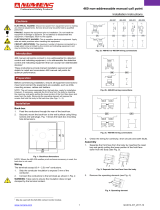
1 Lifting Eye
2 Lifting Forks
Use lifting eye or lifting forks to
move unit.
If using lifting forks, extend forks
beyond opposite side of unit.
3 Rating Label
Use rating label to determine input
power needs.
4 Line Disconnect Device
Locate unit near correct input pow-
er supply.
OR
1
3
Movement
Location And Airflow
2
18 in
4
(460 mm)
18 in
(460 mm)
Special installation may be required
where gasoline or volatile liquids are
present − see NEC Article 511 or CEC
Section 20.
Figure 3-2. Movement And Location Of Welding Power Source

OM-350 Page 4
Overall dimensions (A, B, and C) include lifting eye, handles, hardware, etc.
NOTE
ST-800 338
Inches Millimeters
A 47 1193
B 31-1/4 794
C 22-3/4 577
D 25-1/2 648
E 2-13/16 71
F 1-15/16 49
G 19 483
H 9/16 Dia 14 Dia
4 Holes 4 Holes
C
B
A
E
F
G
D
H
Figure 3-3. Overall Dimensions And Base Mounting Hole Layout
3-3. Selecting And Preparing Weld Output Cables
sb6.5* 5/94 − S-0752
1 Weld Output Cable
Determine total cable length in weld
circuit and maximum welding am-
peres. Use Table 3-1 to select prop-
er cable size.
Use shortest cables possible.
Do not use damaged cables.
2 Terminal Lug
Use lugs of proper amperage
capacity and hole size for connect-
ing to work clamp or electrode
holder, and weld output terminals.
3 Insulated Electrode Holder
4 GTAW Torch
Install according to manufacturer’s
instructions.
5 Work Clamp
Install onto work cable.
10 ft (3 m)
1
Total Cable
Length In Weld
Circuit = 20 ft (6 m)
10 ft (3 m)
For Example,
2
5
2
43
OR
Tools Needed:
Figure 3-4. Selecting And Preparing Weld Output Cables
Table 3-1. Weld Cable Size*
Total Cable (Copper) Length In Weld Circuit Not Exceeding
100 ft (30 m) Or Less
150 ft
(45 m)
200 ft
(60 m)
250 ft
(70 m)
300 ft
(90 m)
350 ft
(105 m)
400 ft
(120 m)
Welding
Amperes
10 To 60%
Duty Cycle
60 Thru 100%
Duty Cycle
10 Thru 100% Duty Cycle
100 4 4 4 3 2 1 1/0 1/0
150 3 3 2 1 1/0 2/0 3/0 3/0
200 3 2 1 1/0 2/0 3/0 4/0 4/0
250 2 1 1/0 2/0 3/0 4/0 2-2/0 2-2/0
300 1 1/0 2/0 3/0 4/0 2-2/0 2-3/0 2-3/0
350 1/0 2/0 3/0 4/0 2-2/0 2-3/0 2-3/0 2-4/0
400 1/0 2/0 3/0 4/0 2-2/0 2-3/0 2-4/0 2-4/0
500 2/0 3/0 4/0 2-2/0 2-3/0 2-4/0 3-3/0 3-3/0
600 3/0 4/0 2-2/0 2-3/0 2-4/0 3-3/0 3-4/0 3-4/0
*Weld cable size (AWG) is based on either a 4 volts or less drop or a current density of at least 300 circular mils per ampere. S-0007-D

OM-350 Page 5
3-4. Lower Front Panel
Ref. ST-144 405-B
1 Work Output Terminal
2 Electrode Output Terminal
3 High Frequency Intensity
Control (See Figure 4-10)
4 Spark Gaps (See Section 5-3)
5 Circuit Breaker CB1 (See
Section 5-2)
6 Gas Valve Fittings
7 115 VAC Duplex Receptacle
8 Remote Contactor And Cur-
rent Control Receptacle
1
2
3
4
5
6
7
8
Figure 3-5. Lower Front Panel
3-5. Installing Gas Supply
WARNING
CYLINDERS can explode if damaged.
• Keep cylinders away from welding and other
electrical circuits.
• Never touch cylinder with welding electrode.
• Always secure cylinder to running gear, wall, or
other stationary support.
BUILDUP OF SHIELDING GAS can harm
health or kill.
• Shut off shielding gas supply when not in use.
warn4.1 9/91
Chain cylinder to running gear, wall,
or other stationary support so it
cannot fall and break off valve.
1 Cap
2 Cylinder Valve
Remove cap, stand to side of valve,
and open valve slightly. Gas flow
blows dust and dirt from valve.
Close valve.
3 Cylinder
4 Regulator/Flowmeter
Install so face is vertical.
5 Gas Hose Connection
Fitting has 5/8-18 right-hand
threads. Obtain and install gas
hose.
6 Flow Adjust
Typical flow rate is 15 cfh (cubic feet
per hour).
Make sure flow adjust is closed
when opening cylinder to avoid
damage to the flowmeter.
7 Gas In Fitting
8 Gas Out Fitting
The gas In and gas Out fittings have
5/8-18 right-hand threads.
Connect hose as shown.
Close access door.
ssb3.3* 5/94 − Ref. ST-158 697- / Ref. C-085 461
Tools Needed:
5/8, 1-1/8 in
4
5
6
1
2
3
Argon Gas
7
IN
OUT
8
GAS
To Torch
Figure 3-6. Shielding Gas Connections

OM-350 Page 6
3-6. 115 Volts AC Duplex Receptacle
1 115 Volts AC Duplex
Receptacle
This welding power source sup-
plies up to 15 amperes of 115 volts
ac power.
Receptacle is protected from over-
load by circuit breaker CB1 (see
Section 5-2).
1
115V 15 A AC
Figure 3-7. 115 Volts AC Duplex Receptacle
3-7. Connecting To Weld Output Terminals
WARNING
ELECTRIC SHOCK can kill.
• Do not touch live electrical parts.
• Turn Off welding power source, and disconnect input power before making any weld output connections.
SERIOUS ELECTRIC SHOCK OR FIRE CAN RESULT FROM WELD CURRENT ON CASE and in
ground conductor.
• Do not let torch cable adapter hit screwheads, access door, case, or any parts.
• Install adapter as shown in Figure 3-8.
warn9.1 3/94
1 Work Weld Output Terminal
2 Electrode Weld Output Terminal
3 Torch Cable Adapter
Adapter connects power and water to
torch and cooling system or drain.
4 Access Door
Connect cables as shown.
Close and secure access door.
Tools Needed:
3/4 in
SMAW Connections GTAW Connections
Work
Work
OR
Use only a proper torch cable adapter
positioned so it does not hit frame,
hardware, or door during operation.
sb9.1 3/94 − Ref. ST-144 405-B / ST-800 578
Location of Terminals
1
Gas Or
Water Hose
1
2
3
1
2
2
4
Figure 3-8. Weld Output Connections

OM-350 Page 7
3-8. Remote 14 Receptacle Information And Connections
sb7.1 5/94 − Ref. ST-144 405-B / Ref. S-0004-A / S-0750
1 Remote 14 Receptacle RC2
(See Table 3-2)
2 Keyway
3 Plug
4 Threaded Collar
To connect to receptacle, align
keyway, insert plug, and tighten
threaded collar.
3
4
AJ
B
K
I
C
L
NH
D
M
G
E
F
12
OR
Figure 3-9. Remote 14 Connections
Table 3-2. Remote 14 Socket Information
A 24 volts ac.
B Contact closure to A completes 24 volts ac contactor control circuit.
C +10 volts dc output to remote control.
D Remote control circuit common.
E 0 to +10 volts dc input command signal from remote control.
Socket Information
*The remaining sockets are not used.
Socket*

OM-350 Page 8
3-9. Connecting Input Power
WARNING
HIGH-FREQUENCY RADIATION can
interfere with radio navigation, safety
services, computers, and communica-
tions equipment.
• Have only qualified person familiar with electronic
equipment perform this installation.
• Read and follow entire Section 7 for proper location
and installation requirements for high-frequency
equipment before installing unit.
ELECTRIC SHOCK can kill.
• Do not touch live electrical parts.
• Turn Off welding power source, and disconnect
input power before inspecting or installing.
• Have only qualified persons install unit.
• Installation must meet National Electrical Code and
all other codes.
swarn13.2 4/93
A. Positioning Jumper Links
ssb5.1 2/92 − ST-800 337-A
Jumper links allow operation on dif-
ferent input voltages and are facto-
ry set for the highest input voltage.
Check input voltage available at
site.
Remove side panel to check jump-
er links.
1 Input Voltage Label − Only
One Is On Unit
Look at jumper links and compare
link position with unit label.
2 Input Voltage Jumper Links
Move links to match input voltage.
For example, use 230 volts position
when 230 volts input power is avail-
able.
Reinstall side panel or go on to
Figure 3-11.
1
Tools Needed:
S-048 604-A S-081 896-A
2
1/2 in
3/8 in
Figure 3-10. Input Voltage Jumper Links Location

S-0092-G
OM-350 Page 9
B. Connecting Input Power
Have only qualified persons make
this installation.
Remove side panel.
1 Line Disconnect Device Of
Proper Rating
2 Input Conductors
3 Grounding Conductor
Select size and length using
Table 3-3. Conductor rating must
comply with national, state, and
local electrical codes. Use lugs of
proper amperage capacity and cor-
rect hole size.
4 Strain Relief Connector
Insert conductors through strain
relief.
5 Input Terminal Board
6 Line Terminals
7 Welding Power Source
Ground Terminal
Connect grounding conductor to
ground terminal first. Then connect
input conductors to line terminals.
8 Disconnect Device Ground
Terminal
Install and connect grounding
conductor and input conductors in
conduit or equivalent to deener-
gized line disconnect device.
Connect grounding conductor first,
then line input conductors.
Be sure grounding conductor goes
to an earth ground.
Reinstall side panel.
9 Overcurrent Protection
Select type and size using
Table 3-3. Install into deenergized
line disconnect device (fused dis-
connect switch shown).
ssb2.4 1/94 − SB-127 873-B
1
Tools Needed:
9
5
4
6
2
7
3
1/2 in
3/8 in
8
Figure 3-11. Input Power Connections
Table 3-3. Electrical Service Requirements*
Input Voltage
200 230 460 575
Input Amperes At Rated Output
206 180 90 72
Recommended Standard Fuse Or Circuit Breaker
Rating In Amperes
1
300 250 125 110
Input Conductor Size In AWG/Kcmil
2
2/0 1/0 4 6
Max Input Conductor Length In Feet (Meters)
3
139 (42) 163 (50) 318 (97) 336 (102)
Grounding Conductor Size In AWG/Kcmil
4
4 4 6 6
*
These values are calculated from the 1993 edition of the National Electrical Code (NEC).
1 Recommended fuse or circuit breaker size is that closest to 150% of rated input amperage of the welding power source. Article 630-12(a) of NEC
allows fuse or circuit breaker sizing up to 200% of rated input amperage.
2 Input conductor size is for insulated copper wire with 75°C rating with not more than three single current-carrying conductors in a cable or raceway
(Table 310-16 of NEC).
3 Maximum length is to prevent more than a 3% voltage drop between service entrance and input terminals of the welding power source (Articles
210-19(a) and 215-2(b) of NEC).
4 The grounding conductor shall be colored or identified as specified in the NEC. Grounding conductor size for copper wire is not required to be larger
than input conductor (Article 250-95 of NEC).

OM-350 Page 10
SECTION 4 − OPERATION
WARNING
ELECTRIC SHOCK can kill.
• Always wear dry insulating gloves.
• Insulate yourself from work and ground.
• Do not touch live electrical parts.
• Keep all panels and covers securely in place.
FUMES AND GASES can be hazardous
to your health.
• Keep your head out of the fumes.
• Ventilate area, or use breathing device.
• Read Material Safety Data Sheets (MSDSs) and
manufacturer’s instructions for material used.
WELDING can cause fire or explosion.
• Do not weld near flammable material.
• Watch for fire; keep extinguisher nearby.
• Do not locate unit over combustible surfaces.
• Do not weld on closed containers.
• Allow work and equipment to cool before handling.
ARC RAYS can burn eyes and skin;
NOISE can damage hearing.
• Wear welding helmet with correct shade of filter.
• Wear correct eye, ear, and body protection.
MOVING PARTS can cause injury.
• Keep away from moving parts.
• Keep all doors, panels, covers, and guards closed
and securely in place.
MAGNETIC FIELDS FROM HIGH CUR-
RENTS can affect pacemaker operation.
• Pacemaker wearers keep away.
• Wearers should consult their doctor before going
near arc welding, gouging, or spot welding opera-
tions.
See Safety Precautions at beginning of manual for ba-
sic welding safety information.
swarn6.1 10/91
Ref. ST-144 405-B
1 Output (Contactor) Switch
2 Amperage Control Switch
3 Start Amperage Switch
4 Start Amperage Control
5 Amperage Adjustment Control
6 Voltmeter
7 Ammeter
8 Power Switch
9 Pilot Light
10 Postflow Time Control
11 AC Balance Control
12 Polarity Switch
13 AC/DC Switch
14 Crater Fill Switch
15 High Frequency Switch
1
2
3
4
5
6
7
8
9
10
11
12
13
15
14
Figure 4-1. Controls

OM-350 Page 11
Wear the following while welding:
1 Dry, Insulating Gloves
2 Safety Glasses With Side
Shields
3 Welding Helmet With Correct
Shade Of Filter (See ANSI
Z49.1)
sb3.1 1/94
123
Figure 4-2. Safety Equipment
1 Work Clamp
Connect work clamp to a clean,
paint-free location on workpiece, as
close to weld area as possible.
Use wire brush or sandpaper to
clean metal at weld joint area. Use
chipping hammer to remove slag
after welding.
sb4.1 2/93
Tools Needed:
1
Figure 4-3. Work Clamp
WARNING
ELECTRIC SHOCK can kill.
• Do not use AC output in damp areas, if movement is
confined, or if there is a danger of falling.
• Use AC output ONLY if required for the welding
process.
• If AC output is required, use remote output control.
• Read Safety Precautions at beginning of this
manual.
ARCING can damage switch.
• Do not change AC/DC or Polarity switch position
while welding.
Arcing inside switch can damage contacts, causing
switch to fail.
warn6.3 4/92 / warn5.1* 2/93
Ref. ST-116 740-A
1 AC/DC Switch
Use switch to select type of weld
output.
2 Polarity Switch
Use switch to select either DC
Electrode Positive (DCEP) or DC
Electrode Negative (DCEN) output.
1
2
Figure 4-4. AC/DC And Polarity Switches

OM-350 Page 12
1 Amperage Adjustment Control
Use control to select weld output
amperage.
2 Amperage Control Switch
Use switch to select way of control-
ling amperage adjustment.
For front panel control, place switch
in the Panel position.
For remote control, place switch in
Remote 14 position (see Section
3-8).
3 Fingertip Control
4 Remote Hand Control
5 Remote Foot Control
See example below.
1
Set Switch Adjust Remote ControlSet Desired Maximum Amperage
3
4
5
2
Example Of Front Panel Amperage Control
In Example:
Min = 25 A AC
Max = 300 A AC
Figure 4-5. Amperage/Voltage Controls
1 Start Switch
On − provides start amperage
control;
Off − no start amperage control.
2 Start Amperage Control
Use control to select amperage lev-
el for arc starting that is different
than Amperage Adjustment control
setting.
The numbers are a percentage of
the maximum welding amperage of
the unit and not an actual value.
1 2
Figure 4-6. Start Amperage Controls

OM-350 Page 13
WARNING
ELECTRIC SHOCK can kill.
• Do not touch live electrical parts.
• Do not touch weld output terminals when contactor is energized.
• Do not touch electrode and work clamp at the same time.
swarn7.1 10/91
1 Output (Contactor) Switch
Use switch to select way of control-
ling unit output.
For weld output, place switch in On
position.
For remote output control, place
switch in Remote 14 position (see
Section 3-8).
1
Weld output terminals are
energized when switch is
On and Power is On.
Figure 4-7. Output (Contactor) Switch
S-0795-A
1 AC Balance Control
Use control to change the ac output
square wave.
Turn control towards 10 to obtain
deeper penetration. Turn control to-
wards 0 to obtain more cleaning ac-
tion of the workpiece. The wave
shape of position 3 (balanced), pro-
vides equal penetration and clean-
ing action, and is a recommended
starting point for GTAW.
50% Electrode
68% Electrode
Negative
50% Electrode
Negative
32% Electrode
Positive
55% Electrode
Positive
45% Electrode
Negative
Positive
3
10
0
1
Balance Control Waveform Examples
More Penetration
Balanced
More Cleaning
Figure 4-8. AC Balance Control

OM-350 Page 14
1 Postflow Time Control
Use control to set the length of time
in seconds gas (and coolant if appli-
cable) flows after welding stops.
1
Figure 4-9. Postflow Time Control
USING HIGH FREQUENCY WITH THE SHIELDED METAL ARC WELDING (SMAW) PROCESS can result in
serious personal injury.
• Place the High Frequency switch in the Off position before using the Shielded Metal Arc Welding (SMAW) Process.
WARNING
1 High Frequency Switch
Off − No HF. Use Off for SMAW
welding.
Start − provides HF for arc starting
only.
Continuous − provides HF continu-
ously throughout the weld.
2 High Frequency Intensity
Control (Figure 3-5)
Use control to change amount of
HF energy used to start and main-
tain the arc. Set as low as practical
to prevent interfering with electronic
equipment. Numbers around the
control are for reference only.
21
S-000 485
HF
Figure 4-10. High Frequency Controls
1 Crater Fill Switch
In − provides crater time;
Out − provides no crater time.
Place switch in the Out position for
SMAW.
Use crater to taper weld output from
setting of the Amperage Adjust-
ment control to the minimum of the
unit.
When using the crater time circuit,
set Postflow Time Control (see
Figure 4-9) for at least 8 to 10
seconds.
1
Figure 4-11. Crater Fill Switch

OM-350 Page 15
1 Ammeter
Ammeter displays weld amperage
output of unit.
2 Voltmeter
Voltmeter displays voltage at the
weld output terminals, but not nec-
essarily the welding arc due to
cable resistance, poor connec-
tions, etc.
21
Figure 4-12. Ammeter And Voltmeter
1 Power Switch
Use this switch to turn unit and pilot
light On and Off.
1
Figure 4-13. Power Switch

OM-350 Page 16
WARNING
BUILDUP OF SHIELDING GAS can harm health or kill.
• Shut off shielding gas supply when not in use.
warn1.1 9/91
1 Shielding Gas Cylinder
2 Valve
3 Fingertip Control
4 Foot Control
Open valve on cylinder just before
welding.
Fingertip control or foot control
turns weld output and gas flow on
and off.
Close valve on cylinder when fin-
ished welding.
sb5.3* 5/94 − S-0621-C / S-0769
2
1
43
OR
Figure 4-14. Shielding Gas
Turn On
Shielding Gas
ssb8.1* 12/92
Install &
Connect
Equipment
Select
Tungsten (See
Section 8)
Insert
Tungsten
Into Torch
Put On
Personal Safety
Equipment
Set Controls
Adjust
High-Frequency
Intensity
Turn On
Welding Power
Source
Begin Welding
Figure 4-15. Sequence Of Gas Tungsten Arc Welding (GTAW)
Begin Welding
ssb7.1 9/92
Install &
Connect
Equipment
Select
Electrode
Put On
Personal Safety
Equipment
Set Controls
Insert
Electrode
Into Holder
Turn On
Welding Power
Source
Figure 4-16. Sequence Of Shielded Metal Arc Welding (SMAW)
SECTION 5 − MAINTENANCE & TROUBLESHOOTING
WARNING
ELECTRIC SHOCK can kill.
• Do not touch live electrical parts.
• Turn Off welding power source, and disconnect
input power before inspecting, maintaining, or
servicing.
HOT PARTS can cause severe burns.
• Allow cooling period before maintaining or servicing.
MOVING PARTS can cause injury.
• Keep away from moving parts.
Maintenance to be performed only by qualified persons.
swarn8.1 2/93

OM-350 Page 17
5-1. Routine Maintenance
Turn Off all power before maintaining.
3 Months
Clean
And
Tighten
Weld
Terminals
Replace
Unreadable
Labels
14-Pin Cord
Gas Hose Torch Cable
Replace
Cracked
Parts
Adjust
Spark
Gaps
3 Months
Tape Or
Replace
Cracked
Cables
See
Section
9
− −
3-7
5-3
− −
ST-127 872-A
6 Months
OR
During Heavy Service,
Clean Monthly
Blow Out
Or
Vacuum
Inside
−−
Figure 5-1. Maintenance Schedule
5-2. Overload Protection
READ SAFETY BLOCKS at start of
Section 5 before proceeding.
WARNING
Ref. ST-144 405-B
1 Circuit Breaker CB1
CB1 protects the 115 volts ac wind-
ing of transformer T1 from over-
load. If CB1 opens, high frequency
and output to the 115 volts ac du-
plex receptacle stop.
Press button to reset breaker.
Close access door.
1
Figure 5-2. Circuit Breaker CB1
/