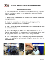
Kawasaki IMP-1354 User manual
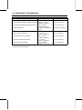
- Category
- Water dispensers
- Type
- User manual
This manual is also suitable for

KX250F
Motorcycle
Service Manual


This quick reference guide will assist
you in locating a desired topic or pro-
cedure.
•Bend the pages back to match the
black tab of the desired chapter num-
ber with the black tab on the edge at
each table of contents page.
•Refer to the sectional table of contents
for the exact pages to locate the spe-
cific topic required.
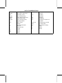
Quick Reference Guide
General Information 1 j
Periodic Maintenance 2 j
Fuel System 3 j
Cooling System 4 j
Engine Top End 5 j
Engine Right Side 6 j
Engine Lubrication System 7 j
Engine Removal/Installation 8 j
Crankshaft/Transmission 9 j
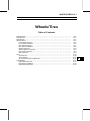
Wheels/Tires 10 j
Final Drive 11 j
Brakes 12 j
Suspension 13 j
Steering 14 j
Frame 15 j
Electrical System 16 j
Appendix 17 j


KX250F
Motorcycle
Service Manual
All rights reserved. No parts of this publication may be reproduced, stored in a retrieval system, or
transmitted in any form or by any means, electronic mechanical photocopying, recording or otherwise,
without the prior written permission of Quality Divis ion/Consumer Products & Machinery Company/Kawasaki
Heavy Industries, Ltd., Japan.
No liability can be accepted for any inaccuracies or omissions in this publication, although every possible
care has been taken to make it as complete and accurate as possible.
The right is reserved to make changes at any time without prior notice and without incurring an obligation
to make such changes to products manufactured previously. See your Motorcycle dealer for the latest
information on product improvements incorporated after this publication.
All information contained in this publication is based on the latest product information available at the time
of publication. Illustrations and photographs in this publication are intended for reference use only and may
not depict actual model component parts.
© 2005 Kawasaki Heavy Industries, Ltd. First Edition (1) : Jul. 8, 2005 (M)

LIST OF ABBREVIATIONS
A ampere(s) lb pound(s)
ABDC after bottom dead center m meter(s)
AC alternating current min minute(s)
ATDC after top dead center N newton(s)
BBDC before bottom dead center Pa pascal(s)
BDC bottom dead center PS horsepower
BTDC before top dead center psi pound(s) per square inch
°C degree(s) Celsius r revolution
DC direct current r/min, rpm revolution(s) per minute
F farad(s) TDC top dead center
°F degree(s) Fahrenheit TIR total indicator reading
ft foot, feet V volt(s)
g gram(s) (mass) W watt(s)
h hour(s) Ω ohm(s)
kg (mass)
kgf (force)
L liter(s)

Foreword
This manual is designed primarily for use by
trained mechanics in a properly equipped shop.
However, it contains enough detail and basic in-
formation to make it useful to the owner who de-
sires to perform his own basic maintenance and
repair work. A basic knowledge of mechanics,
the proper use of tools, and workshop proce-
dures must be understood in order to carry out
maintenance and repair satisfactorily. When-
ever the owner has insufficient experience or
doubts his ability to do the work, all adjust-
ments, maintenance, and repair should be c ar-
ried out only by qualified mechanics.
In order to perform the work efficiently and
to avoid costly mistakes, read the text, thor-
oughly familiarize yourself with the procedures
before starting work, and then do the work care-
fully in a clean area. Whenever special tools or
equipment are specified, do not use makeshift
tools or equipment. Precision measurements
can only be made if the proper instruments are
used, and the use of substitute tools may ad-
versely affect safe operation.
To get the longest life out of your vehicle:
•
Follow the Periodic Maintenance Chart in the
Service Manual.
•
Be alert for problems and non-scheduled
maintenance.
•
Use proper tools and genuine Kawasaki Mo-
torcycle parts. Special tools, gauges, and
testers that are necessary when servicing
Kawasaki motorcycles are introduced by the
Special Tool Catalog or Manual. Genuine
parts provided as spare parts are listed in the
Parts Catalog.
•
Follow the procedures in this manual care-
fully. Don’t take shortcuts.
•
Remember to keep complete records of main-
tenance and repair with dates and any new
parts installed.
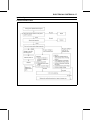
How to Use This Manual
In this manual, the product is divided into
its major systems and these systems make up
the manual’s chapters. The Quick Reference
Guide shows you all of the product’s system
and assists in locating their chapters. Each
chapter in turn has its own comprehensive Ta-
ble of Contents.
For example, if you want stick coil information,
use the Quick Reference Guide to locate the
Electrical System chapter. Then, use the Table
of Contents on the first page of the chapter to
find the Stick Coil section.
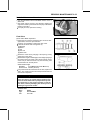
Whenever you see these WARNING and
CAUTION symbols, heed their i nstructions!
Always follow safe operating and maintenance
practices.
WARNING
This warning symbol identifies special
instructions or procedures which, if not
correctly followed, could result in per-
sonal injury, or loss of life.
CAUTION
This caution symbol identifies special
instructions or procedures which, if not
strictly observed, could result in dam-
age to or destruction of equipment.
This manual contains four more symbols (in
addition to WARNING and CAUTION) which will
help you distinguish different types of informa-
tion.
NOTE
○
This note symbol ind icates points of par-
ticular interest for more efficient and con-
venient operation.
•
Indicates a procedural step or work to be
done.
○
Indicates a procedural sub-step or how to do
the work of the procedural step it follows. It
also precedes the text of a NOTE.
Indicates a conditional step or what action to
take based on the results of the test or inspec-
tion in the procedural step or sub-step it fol-
lows.
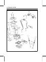
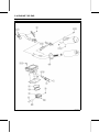
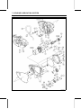
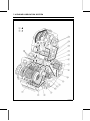
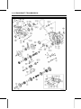
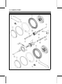
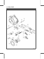
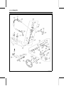
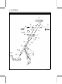
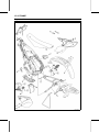
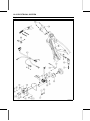
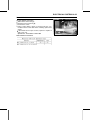
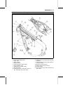
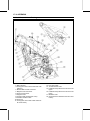
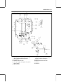
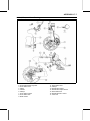
In most chapters an exploded view illustration
of the system components follows the Table of
Contents. In these illustrations you will find the
instructions indicating which parts require spec-
ified tightening torque, oil, grease or a locking
agent during assembly.


GENERAL INFORMATION 1-1
1
General Information
Table of Contents
Before Servicing ..................................................................................................................... 1-2
Model Identification................................................................................................................. 1-7
General Specifications............................................................................................................ 1-8
Unit Conversion Table ............................................................................................................ 1-10

1-2 GENERAL INFORMATION
Before Servicing
Before starting to perform an inspection service or carry out a disassembly and reassembly opera-
tion on a motorcycle, read the precautions given below. To facilitate actual operations, notes, illustra-
tions, photographs, cautions, and detailed descriptions have been included in each chapter wherever
necessary. This section explains the items that require particular attention during the removal and
reinstallation or disassembly and reassembly of general parts.
Especially n ote the following:
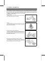
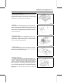
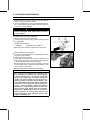
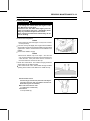
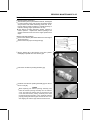
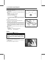
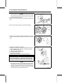
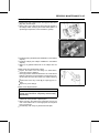
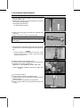
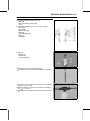
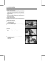
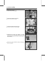
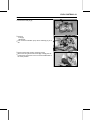
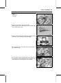
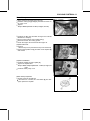
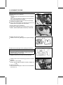
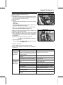
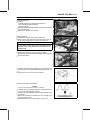
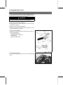
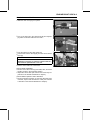
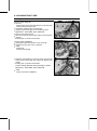
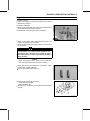
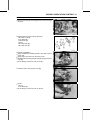
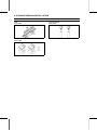
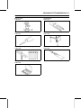
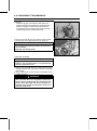
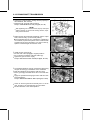
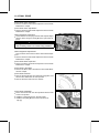
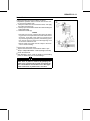
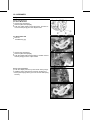
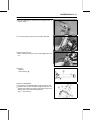
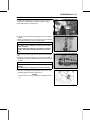
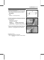
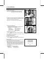
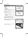
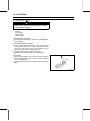
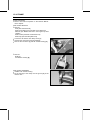
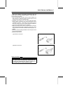
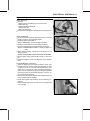
Edges of Parts
Lift large or heavy parts wearing gloves to prevent injury
from possible sharp edges on the parts.
Solvent
Use a high flush point solvent when cleaning parts. High
flush point solvent s hould be used according to directions
of the solvent manufacturer.
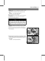
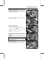
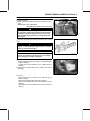
Cleaning vehicle before disassembly
Clean the vehicle thoroughly before disassembly. Dirt or
other foreign materials entering into sealed areas during ve-
hicle disassembly can cause excessive wear and decrease
performance of the vehicle.
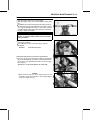
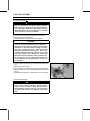
Arrangement and Cleaning of Removed Parts
Disassembled parts are easy to confuse. Arrange the
parts according to the order the parts were disassembled
and clean the parts in order prior to assembly.

GENERAL INFORMATION 1-3
Before Servicing
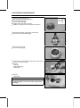
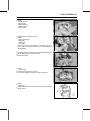
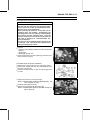
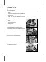
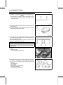
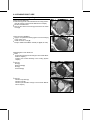
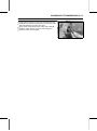
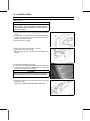
Storage of Removed Parts
After all the parts including subassembly parts have been
cleaned, store the parts in a clean area. Put a clean cloth
or plastic sheet over the parts to protect from any foreign
materials that m ay collect before re-assembly.
Inspection
Reuse of worn or damaged parts may lead to serious ac-
cident. Visually inspect removed parts for corrosion, discol-
oration, or other damage. Refer to the appropriate sections
of this manual for service limits on individual parts. Replace
the parts if any damage has been found or if the part is be-
yond its service limit.
Replacement Parts
Replacement Parts must be KAWASAKI genuine or rec-
ommended by KAWASAKI. Gaskets, O rings, Oil seals,
Grease seals, circlips or cotter pins must be replaced with
new ones whenever disassembled.
Assembly Order
In most cases assembly order is the reverse of disassem-
bly, however, if assembly order is provided in this Service
Manual, follow the procedures given.
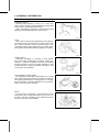
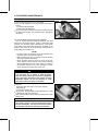
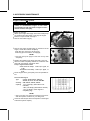
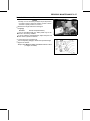
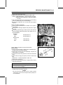
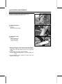
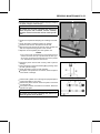
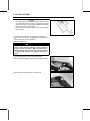
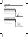
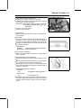
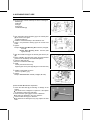
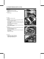
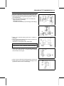
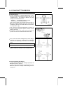
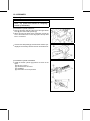
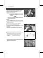
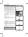
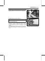
Tightening Sequ ence
Generally, when installing a part with several bolts, nuts,
or screws, start them all in their holes and tighten them to
a snug fit. Then tighten them according to the specified se-
quence to prevent case warpage or deformation which can
lead to malfunction. Conversely when loosening the bolts,
nuts, or screws, first loosen all of them by about a quar-
ter turn and them remove them. If the specified tightening
sequence is not indicated, tighten the fasteners alternating
diagonally.

1-4 GENERAL INFORMATION
Before Servicing
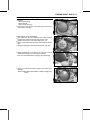
Tightening Torque
Incorrect torque applied to a bolt, nut, or screw may
lead to serious damage. Tighten fasteners to the specified
torque using a good quality torque wrench.
Often, the tightening sequence is followed twice-initial
tightening and final tightening with torque wrench.
Force
Use common sense during disassembly and assembly,
excessive force can cause expensive or hard to repair dam-
age. When necessary, remove screws that have a non
-permanent locking agent applied using an impact driver.
Use a plastic-faced mallet whenever tapping is necessary.
Gasket, Oring
Hardening, shrinkage, or damage of both gaskets
and O-rings after disassembly can reduce sealing per-
formance. Remove old gaskets and clean the sealing
surfaces thoroughly so that no gasket material or other
material remains. Install new gaskets and replace used
O-rings when re-assembling
Liquid Gasket, Locking Agent
For applications that require Liquid Gasket or a Locking
agent, clean the surfaces so that no oil residue remains be-
fore applying liquid gasket or locking agent. Do not apply
them excessively. Excessive application can clog oil pas-
sages and cause serious damage.
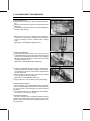
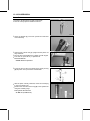
Press
For items such as bearings or oil seals that must be
pressed into place, apply small amount of oil to the con-
tact area. Be sure to maintain proper alignment and use
smooth movements when installing.

GENERAL INFORMATION 1-5
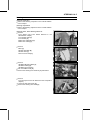
Before Servicing
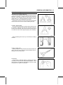
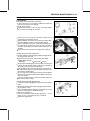
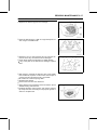
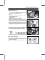
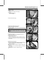
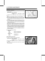
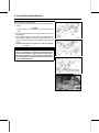
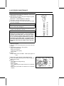
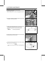
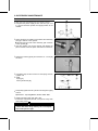
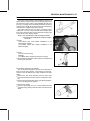
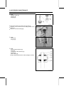
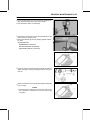
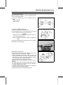
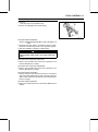
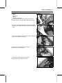
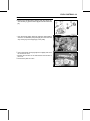
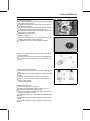
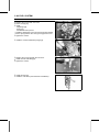
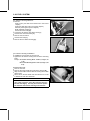
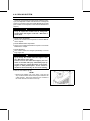
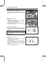
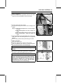
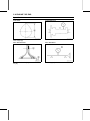
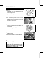
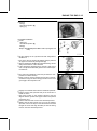
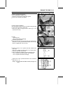
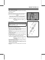
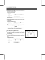
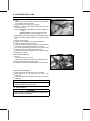
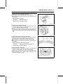
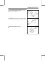
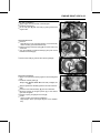
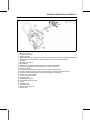
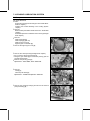
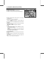
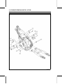
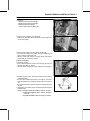
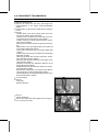
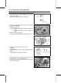
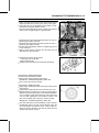
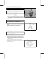
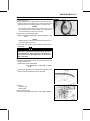
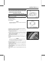
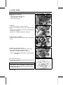
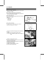
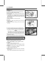
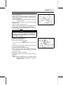
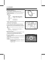
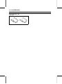
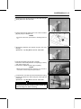
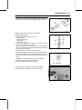
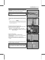
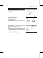
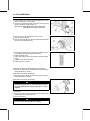
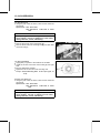
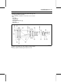
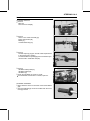
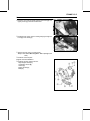
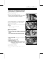
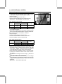
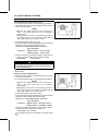
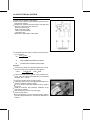
Ball Bearing and Needle Bearing
Do not remove pressed ball or needle unless removal is
absolutely necessary. Replace with new ones whenever
removed. Press bearings with the manufacturer and size
marks facing out. Press the bearing into place by putting
pressure on the correct bearing race as shown.
Pressing the incorrect race can cause pressure between
the inner and outer race and result in bearing damage.
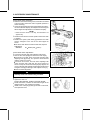
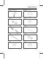
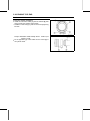
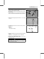
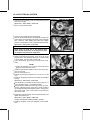
Oil Seal, Grease Seal
Do not remove pressed oil or grease seals unless removal
is necessary. Replace with new ones whenever removed.
Press new oil seals with manufacture and size marks facing
out. Make sure the seal is aligned properly when installing.
Apply specified grease to the lip of seal before installing
the seal.
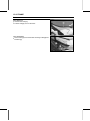
Circlips, Cotter Pins
Replace circlips or cotter pins that were removed with new
ones. Take care not to open the clip excessively when in-
stalling to prevent deformation.
Lubrication
It is important to lubricate rotating or sliding parts during
assembly to minimize wear during initial operation. Lubri-
cation points are called out throughout this manual, apply
the specific oil or grease as specified.

1-6 GENERAL INFORMATION
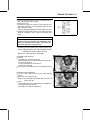
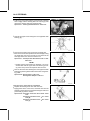
Before Servicing
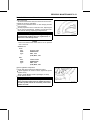
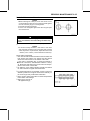
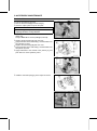
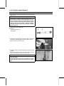
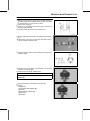
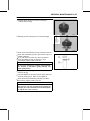
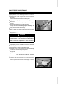
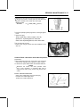
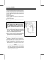
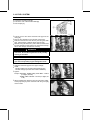
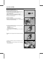
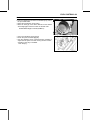
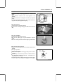
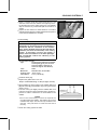
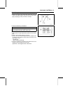
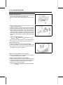
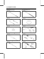
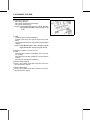
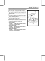
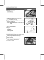
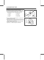
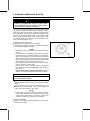
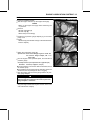
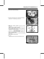
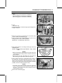
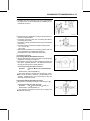
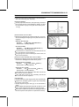
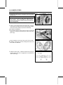
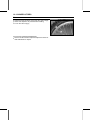
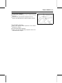
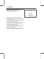
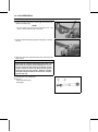
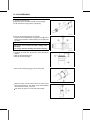
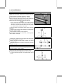
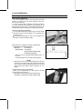
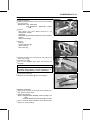
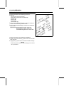
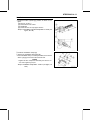
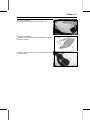
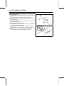
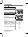
Direction of Engine Rotation
When rotating the c rankshaft by hand, the free play
amount of rotating direction will affect the adjustment. Ro-
tate the crankshaft to positive direction (clockwise viewed
from output side).
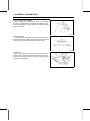
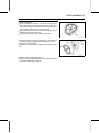
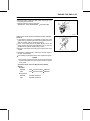
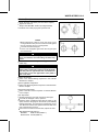
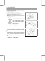
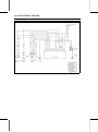
Electrical Wires
A two-color wire is identified first by the primary color and
then the stripe color. Unless instructed otherwise, electrical
wires must be connected to those of the same color.
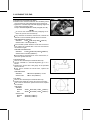
Instrument
Use a meter that has enough accuracy for an accurate
measurement. Read the manufacture’s instructions thor-
oughly before using the meter. Incorrect values may lead
to improper adjustments.

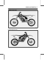
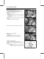
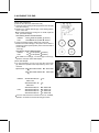
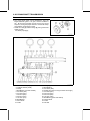
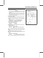
GENERAL INFORMATION 1-7
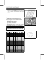
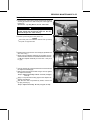
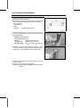
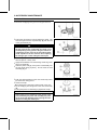
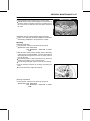
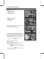
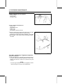
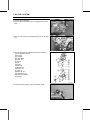
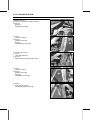
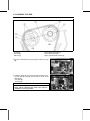
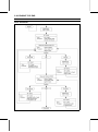
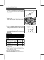
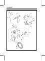
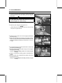
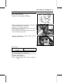
Model Identification
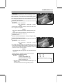
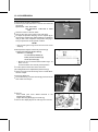
KX250T6F Left Side View
KX250T6F Right Side View

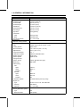
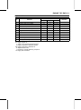
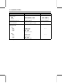
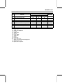
1-8 GENERAL INFORMATION
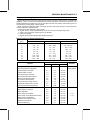
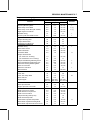
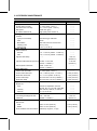
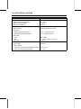
General Specifications
Items KX250T6F
Dimensions
Overall Length 2 160 mm (85.04 in.)
Overall Width 820 mm (32.3 in.)
Overall Height 1 270 mm (50 in.)
Wheelbase 1 469 mm (57.83 in.)
Road Clearance 372 mm (14.6 in.)
Seat Height 960 mm (37.8 in.)
Dry Mass 92.5 kg (204 lb)
Curb Mass:
Front 49.9kg(110lb)
Rear 52.6kg(116lb)
Fuel Tank Capacity 7.2 L (1.9 US gal)
Performance
Minimum Turning Radius –
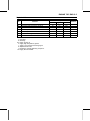
Engine
Type 4-stroke, single cylinder, DOHC 4 valve
Cooling System Liquid-cooled
Bore and Stroke 77.0 × 53.6 mm (3.03 × 2.11 in.)
Displacement 249 mL (15.2 cu in.)
Compression Ratio 13.5 : 1
Carburetion System Carburetor, KEIHIN FCR37
Starting System Primary kick
Ignition System Digital AC-CDI
Timing Advance
Ignition Timing BTDC 8° @2 000 r/min (rpm)
Spark Plug NGK CR8E
Valve Timing
Inlet
Open BTDC 41°
Close ABDC 71°
Duration
292°
Exhaust
Open BBDC 69°
Close ATDC 49°
Duration 298°
Lubrication System Forced lubrication (semi-dry sump)
Engine Oil:
Type
API SG, SH, SJ or SL with JASO MA
Viscosity
SAE 10W-40
Capacity 1.5 L (1.6 USqt)
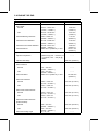
Drive Train
Primary Reduction System:
Type
Gear
Reduction Ratio
3.350 (67/20)

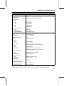
GENERAL INFORMATION 1-9
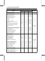
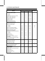
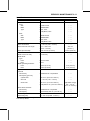
General Specifications
Items KX250T6F
Clutch Type
Wet, multi disc, Manual
Transmission:
Type 5-speed, constant mesh, return shift
Gear ratios:
1st 2.142 (30/14)
2nd 1.785 (25/14)
3rd
1.444 (26/18)
4th
1.200 (24/20)
5th
1.052 (20/19)
Final Drive System:
Type Chain drive
Reduction Ratio 3.692 (48/13)
Overall Drive Ratio 13.020 @Top gear
Frame
Type semi-double cradle
Steering Angle 42° to either side
Caster (rake angle) 27.7°
Trail 119 mm (4.69 in.)
Front tire:
Size 80/100-21 51M
Make/Type BRIDGESTONE, M401, Tube type
BRIDGESTONE M201 (EUR), Tube type
Rear tire:
Size 100/90-19 57M
Make/Type BRIDGESTONE, M402, Tube type
BRIDGESTONE M202 (EUR), Tube type
Front suspension:
Type Telescopic fork (up side down)
Wheel travel 315 mm (12.4 in.)
Rear suspension:
Type
Swingarm (New Uni-trak)
Wheel travel
310 mm (12.2 in.)
Brake type:
Front and Rear Single disc
Effective disc diameter:
Front (effect. dia.) 225 mm (8.86 in.)
Rear (effect. dia.) 215 mm (8.46 in.)
EUR: Europe Model
Specifications are subject to change without notice, and may not apply to every country.

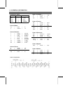
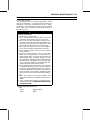
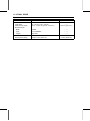
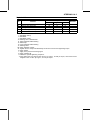
1-10 GENERAL INFORMATION
Unit Conversion Table
Prefixes for Units:
Prefix Symbol
Power
mega M × 1 000 000
kilo k × 1 000
centi c ×0.01
milli m ×0.001
micro µ × 0.000001
Units of Mass:
kg ×2.205=lb
g × 0.03527 = oz
Units of Volume:
L × 0.2642 =
gal (US)
L × 0.2200 = gal (imp)
L × 1.057 = qt (US)
L × 0.8799 = qt (imp)
L×2.113=
pint (US)
L × 1.816 =
pint (imp)
mL × 0.03381 =
oz (US)
mL × 0.02816 = oz (imp)
mL × 0.06102 = cu in
Units o f Force:
N × 0.1020 = kgf
N × 0.2248 = lb
kgf
×9.807=N
kgf
×2.205=lb
Units of Length:
km × 0.6214 = mile
m × 3.281 = ft
mm × 0.03937 = in
Units o f Torque:
N·m × 0.1020 = kgf·m
N·m × 0.7376 =
ft·lb
N·m × 8.851 = in·lb
kgf·m
× 9.807 = N·m
kgf·m × 7.233 = ft·lb
kgf·m × 86.80 = in·lb
Units o f Pressure:
kPa × 0.01020 = kgf/cm²
kPa × 0.1450 = psi
kPa × 0.7501 = cm Hg
kgf/cm²
× 98.07 = kPa
kgf/cm² × 14.22 = psi
cmHg×1.333=kPa
Units o f Speed:
km/h × 0.6214 = mph
Units o f Power:
kW × 1.360 =
PS
kW ×1.341=HP
PS
× 0.7355 = kW
PS × 0.9863 = HP
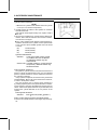
Units of Temperature:

PERIODIC MAINTENANCE 2-1
2
Periodic Maintenance
Table of Contents
Periodic Maintenance Chart ................................................................................................... 2-3
Torque and Locking Agent...................................................................................................... 2-5
Specifications ......................................................................................................................... 2-10
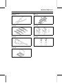
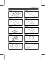
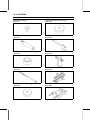
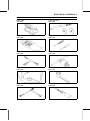
Special Tools .......................................................................................................................... 2-12
Periodic Maintenance Procedures.......................................................................................... 2-13
Fuel System......................................................................................................................... 2-13
Fuel Hose and Connection Inspection .............................................................................. 2-13
Throttle Grip Free Play Inspection .................................................................................... 2-13
Throttle Grip Free Play Adjustment................................................................................... 2-13
Hot Start Lever Free Play Inspection ................................................................................ 2-14
Idle Speed Inspection (Carburetor Inspection) ................................................................. 2-14
Idle Speed Adjustment (Carburetor Adjustment) .............................................................. 2-15
Air Cleaner Element Cleaning and Inspection .................................................................. 2-16
Fuel System Clean............................................................................................................ 2-18
Cooling System.................................................................................................................... 2-19
Coolant Level Inspection ................................................................................................... 2-19
Coolant Deterioration Inspection....................................................................................... 2-20
Radiator Hoses and Connections Inspection.................................................................... 2-20
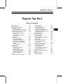
Engine Top End ................................................................................................................... 2-21
Valve Clearance Inspection .............................................................................................. 2-21
Valve Clearance Adjustment............................................................................................. 2-21
Cylinder Head Warp Inspection ........................................................................................ 2-23
Cylinder Wear Inspection.................................................................................................. 2-24
Piston/Cylinder Clearance ................................................................................................ 2-24
Piston, Piston Ring and Piston Pin Replacement ............................................................. 2-24
Exhaust System Inspection ............................................................................................... 2-25
Silencer Packing Change.................................................................................................. 2-25
Engine Right Side ................................................................................................................ 2-26
Clutch Adjustment............................................................................................................. 2-26
Friction and Steel Plates Inspection.................................................................................. 2-27
Engine Lubrication System .................................................................................................. 2-28
Engine Oil Change............................................................................................................ 2-28
Oil Filter Change ............................................................................................................... 2-29
Breather Hose Inspection ................................................................................................. 2-29
Crankshaft/Transmission ..................................................................................................... 2-30
Crankshaft Inspection ....................................................................................................... 2-30
Wheel/Tires.......................................................................................................................... 2-30
Air Pressure Inspection/Adjustment.................................................................................. 2-30
Tires Inspection.................................................................................................................2-31
Spoke Tightness Inspection.............................................................................................. 2-31
Rim Runout Inspection ...................................................................................................... 2-32
Wheel Bearing Inspection ................................................................................................. 2-32
Final Drive............................................................................................................................ 2-33
Drive Chain Wear Inspection ............................................................................................ 2-33
Drive Chain Slack Inspection ............................................................................................ 2-34
Drive Chain Slack Adjustment .......................................................................................... 2-34

2-2 PERIODIC MAINTENANCE
Drive Chain Lubrication..................................................................................................... 2-35
Sprocket Wear Inspection................................................................................................. 2-36
Rear Sprocket Warp Inspection ........................................................................................ 2-36
Brakes.................................................................................................................................. 2-36
Brake Lever and Pedal Adjustment .................................................................................. 2-36
Brake Fluid Level Inspection............................................................................................. 2-38
Brake Fluid Change .......................................................................................................... 2-39
Brake Pad Wear Inspection .............................................................................................. 2-41
Brake Master Cylinder Cup and Dust Seal Replacement ................................................. 2-41
Caliper Piston Seal and Dust Seal Replacement.............................................................. 2-42
Brake Hose and Connection Check.................................................................................. 2-45
Brake Hose Replacement ................................................................................................. 2-45
Suspension.......................................................................................................................... 2-47
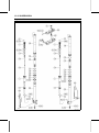
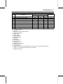
Front Fork Inspection ........................................................................................................ 2-47
Front Fork Oil Change (each fork leg) .............................................................................. 2-47
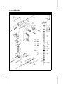
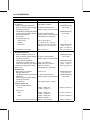
Rear Shock Absorber Oil Change..................................................................................... 2-57
Swingarm and Uni-Trak Linkage Inspection ..................................................................... 2-66
Swingarm and Uni-Track Linkage Pivot Lubricate ............................................................ 2-67
Steering ............................................................................................................................... 2-67
Steering Inspection ........................................................................................................... 2-67
Steering Adjustment ......................................................................................................... 2-67
Stem Bearing Lubrication.................................................................................................. 2-69
Frame .................................................................................................................................. 2-70
Frame Inspection .............................................................................................................. 2-70
Electrical System ................................................................................................................. 2-70
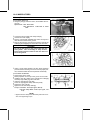
Spark Plug Cleaning and Inspection................................................................................. 2-70
Chassis Parts Lubrication and Cable Inspection ................................................................. 2-71
Lubrication ........................................................................................................................ 2-71
Nut, Bolt, and Fastener Tightness Inspection ...................................................................... 2-72
Tightness Inspection ......................................................................................................... 2-72
Page is loading ...
Page is loading ...
Page is loading ...
Page is loading ...
Page is loading ...
Page is loading ...
Page is loading ...
Page is loading ...
Page is loading ...
Page is loading ...
Page is loading ...
Page is loading ...
Page is loading ...
Page is loading ...
Page is loading ...
Page is loading ...
Page is loading ...
Page is loading ...
Page is loading ...
Page is loading ...
Page is loading ...
Page is loading ...
Page is loading ...
Page is loading ...
Page is loading ...
Page is loading ...
Page is loading ...
Page is loading ...
Page is loading ...
Page is loading ...
Page is loading ...
Page is loading ...
Page is loading ...
Page is loading ...
Page is loading ...
Page is loading ...
Page is loading ...
Page is loading ...
Page is loading ...
Page is loading ...
Page is loading ...
Page is loading ...
Page is loading ...
Page is loading ...
Page is loading ...
Page is loading ...
Page is loading ...
Page is loading ...
Page is loading ...
Page is loading ...
Page is loading ...
Page is loading ...
Page is loading ...
Page is loading ...
Page is loading ...
Page is loading ...
Page is loading ...
Page is loading ...
Page is loading ...
Page is loading ...
Page is loading ...
Page is loading ...
Page is loading ...
Page is loading ...
Page is loading ...
Page is loading ...
Page is loading ...
Page is loading ...
Page is loading ...
Page is loading ...
Page is loading ...
Page is loading ...
Page is loading ...
Page is loading ...
Page is loading ...
Page is loading ...
Page is loading ...
Page is loading ...
Page is loading ...
Page is loading ...
Page is loading ...
Page is loading ...
Page is loading ...
Page is loading ...
Page is loading ...
Page is loading ...
Page is loading ...
Page is loading ...
Page is loading ...
Page is loading ...
Page is loading ...
Page is loading ...
Page is loading ...
Page is loading ...
Page is loading ...
Page is loading ...
Page is loading ...
Page is loading ...
Page is loading ...
Page is loading ...
Page is loading ...
Page is loading ...
Page is loading ...
Page is loading ...
Page is loading ...
Page is loading ...
Page is loading ...
Page is loading ...
Page is loading ...
Page is loading ...
Page is loading ...
Page is loading ...
Page is loading ...
Page is loading ...
Page is loading ...
Page is loading ...
Page is loading ...
Page is loading ...
Page is loading ...
Page is loading ...
Page is loading ...
Page is loading ...
Page is loading ...
Page is loading ...
Page is loading ...
Page is loading ...
Page is loading ...
Page is loading ...
Page is loading ...
Page is loading ...
Page is loading ...
Page is loading ...
Page is loading ...
Page is loading ...
Page is loading ...
Page is loading ...
Page is loading ...
Page is loading ...
Page is loading ...
Page is loading ...
Page is loading ...
Page is loading ...
Page is loading ...
Page is loading ...
Page is loading ...
Page is loading ...
Page is loading ...
Page is loading ...
Page is loading ...
Page is loading ...
Page is loading ...
Page is loading ...
Page is loading ...
Page is loading ...
Page is loading ...
Page is loading ...
Page is loading ...
Page is loading ...
Page is loading ...
Page is loading ...
Page is loading ...
Page is loading ...
Page is loading ...
Page is loading ...
Page is loading ...
Page is loading ...
Page is loading ...
Page is loading ...
Page is loading ...
Page is loading ...
Page is loading ...
Page is loading ...
Page is loading ...
Page is loading ...
Page is loading ...
Page is loading ...
Page is loading ...
Page is loading ...
Page is loading ...
Page is loading ...
Page is loading ...
Page is loading ...
Page is loading ...
Page is loading ...
Page is loading ...
Page is loading ...
Page is loading ...
Page is loading ...
Page is loading ...
Page is loading ...
Page is loading ...
Page is loading ...
Page is loading ...
Page is loading ...
Page is loading ...
Page is loading ...
Page is loading ...
Page is loading ...
Page is loading ...
Page is loading ...
Page is loading ...
Page is loading ...
Page is loading ...
Page is loading ...
Page is loading ...
Page is loading ...
Page is loading ...
Page is loading ...
Page is loading ...
Page is loading ...
Page is loading ...
Page is loading ...
Page is loading ...
Page is loading ...
Page is loading ...
Page is loading ...
Page is loading ...
Page is loading ...
Page is loading ...
Page is loading ...
Page is loading ...
Page is loading ...
Page is loading ...
Page is loading ...
Page is loading ...
Page is loading ...
Page is loading ...
Page is loading ...
Page is loading ...
Page is loading ...
Page is loading ...
Page is loading ...
Page is loading ...
Page is loading ...
Page is loading ...
Page is loading ...
Page is loading ...
Page is loading ...
Page is loading ...
Page is loading ...
Page is loading ...
Page is loading ...
Page is loading ...
Page is loading ...
Page is loading ...
Page is loading ...
Page is loading ...
Page is loading ...
Page is loading ...
Page is loading ...
Page is loading ...
Page is loading ...
Page is loading ...
Page is loading ...
Page is loading ...
Page is loading ...
Page is loading ...
Page is loading ...
Page is loading ...
Page is loading ...
Page is loading ...
Page is loading ...
Page is loading ...
Page is loading ...
Page is loading ...
Page is loading ...
Page is loading ...
Page is loading ...
Page is loading ...
Page is loading ...
Page is loading ...
Page is loading ...
Page is loading ...
Page is loading ...
Page is loading ...
Page is loading ...
Page is loading ...
Page is loading ...
Page is loading ...
Page is loading ...
Page is loading ...
Page is loading ...
Page is loading ...
Page is loading ...
Page is loading ...
Page is loading ...
Page is loading ...
Page is loading ...
Page is loading ...
Page is loading ...
Page is loading ...
Page is loading ...
Page is loading ...
Page is loading ...
Page is loading ...
Page is loading ...
Page is loading ...
Page is loading ...
Page is loading ...
Page is loading ...
Page is loading ...
Page is loading ...
Page is loading ...
Page is loading ...
Page is loading ...
Page is loading ...
Page is loading ...
Page is loading ...
Page is loading ...
Page is loading ...
Page is loading ...
Page is loading ...
Page is loading ...
Page is loading ...
Page is loading ...
Page is loading ...
Page is loading ...
Page is loading ...
Page is loading ...
Page is loading ...
Page is loading ...
Page is loading ...
Page is loading ...
Page is loading ...
Page is loading ...
Page is loading ...
Page is loading ...
Page is loading ...
Page is loading ...
Page is loading ...
Page is loading ...
Page is loading ...
Page is loading ...
Page is loading ...
Page is loading ...
Page is loading ...
Page is loading ...
Page is loading ...
Page is loading ...
Page is loading ...
Page is loading ...
Page is loading ...
Page is loading ...
Page is loading ...
Page is loading ...
Page is loading ...
Page is loading ...
Page is loading ...
Page is loading ...
Page is loading ...
Page is loading ...
Page is loading ...
Page is loading ...
Page is loading ...
Page is loading ...
Page is loading ...
Page is loading ...
Page is loading ...
Page is loading ...
Page is loading ...
Page is loading ...
Page is loading ...
Page is loading ...
Page is loading ...
Page is loading ...
Page is loading ...
Page is loading ...
Page is loading ...
Page is loading ...
Page is loading ...
-
 1
1
-
 2
2
-
 3
3
-
 4
4
-
 5
5
-
 6
6
-
 7
7
-
 8
8
-
 9
9
-
 10
10
-
 11
11
-
 12
12
-
 13
13
-
 14
14
-
 15
15
-
 16
16
-
 17
17
-
 18
18
-
 19
19
-
 20
20
-
 21
21
-
 22
22
-
 23
23
-
 24
24
-
 25
25
-
 26
26
-
 27
27
-
 28
28
-
 29
29
-
 30
30
-
 31
31
-
 32
32
-
 33
33
-
 34
34
-
 35
35
-
 36
36
-
 37
37
-
 38
38
-
 39
39
-
 40
40
-
 41
41
-
 42
42
-
 43
43
-
 44
44
-
 45
45
-
 46
46
-
 47
47
-
 48
48
-
 49
49
-
 50
50
-
 51
51
-
 52
52
-
 53
53
-
 54
54
-
 55
55
-
 56
56
-
 57
57
-
 58
58
-
 59
59
-
 60
60
-
 61
61
-
 62
62
-
 63
63
-
 64
64
-
 65
65
-
 66
66
-
 67
67
-
 68
68
-
 69
69
-
 70
70
-
 71
71
-
 72
72
-
 73
73
-
 74
74
-
 75
75
-
 76
76
-
 77
77
-
 78
78
-
 79
79
-
 80
80
-
 81
81
-
 82
82
-
 83
83
-
 84
84
-
 85
85
-
 86
86
-
 87
87
-
 88
88
-
 89
89
-
 90
90
-
 91
91
-
 92
92
-
 93
93
-
 94
94
-
 95
95
-
 96
96
-
 97
97
-
 98
98
-
 99
99
-
 100
100
-
 101
101
-
 102
102
-
 103
103
-
 104
104
-
 105
105
-
 106
106
-
 107
107
-
 108
108
-
 109
109
-
 110
110
-
 111
111
-
 112
112
-
 113
113
-
 114
114
-
 115
115
-
 116
116
-
 117
117
-
 118
118
-
 119
119
-
 120
120
-
 121
121
-
 122
122
-
 123
123
-
 124
124
-
 125
125
-
 126
126
-
 127
127
-
 128
128
-
 129
129
-
 130
130
-
 131
131
-
 132
132
-
 133
133
-
 134
134
-
 135
135
-
 136
136
-
 137
137
-
 138
138
-
 139
139
-
 140
140
-
 141
141
-
 142
142
-
 143
143
-
 144
144
-
 145
145
-
 146
146
-
 147
147
-
 148
148
-
 149
149
-
 150
150
-
 151
151
-
 152
152
-
 153
153
-
 154
154
-
 155
155
-
 156
156
-
 157
157
-
 158
158
-
 159
159
-
 160
160
-
 161
161
-
 162
162
-
 163
163
-
 164
164
-
 165
165
-
 166
166
-
 167
167
-
 168
168
-
 169
169
-
 170
170
-
 171
171
-
 172
172
-
 173
173
-
 174
174
-
 175
175
-
 176
176
-
 177
177
-
 178
178
-
 179
179
-
 180
180
-
 181
181
-
 182
182
-
 183
183
-
 184
184
-
 185
185
-
 186
186
-
 187
187
-
 188
188
-
 189
189
-
 190
190
-
 191
191
-
 192
192
-
 193
193
-
 194
194
-
 195
195
-
 196
196
-
 197
197
-
 198
198
-
 199
199
-
 200
200
-
 201
201
-
 202
202
-
 203
203
-
 204
204
-
 205
205
-
 206
206
-
 207
207
-
 208
208
-
 209
209
-
 210
210
-
 211
211
-
 212
212
-
 213
213
-
 214
214
-
 215
215
-
 216
216
-
 217
217
-
 218
218
-
 219
219
-
 220
220
-
 221
221
-
 222
222
-
 223
223
-
 224
224
-
 225
225
-
 226
226
-
 227
227
-
 228
228
-
 229
229
-
 230
230
-
 231
231
-
 232
232
-
 233
233
-
 234
234
-
 235
235
-
 236
236
-
 237
237
-
 238
238
-
 239
239
-
 240
240
-
 241
241
-
 242
242
-
 243
243
-
 244
244
-
 245
245
-
 246
246
-
 247
247
-
 248
248
-
 249
249
-
 250
250
-
 251
251
-
 252
252
-
 253
253
-
 254
254
-
 255
255
-
 256
256
-
 257
257
-
 258
258
-
 259
259
-
 260
260
-
 261
261
-
 262
262
-
 263
263
-
 264
264
-
 265
265
-
 266
266
-
 267
267
-
 268
268
-
 269
269
-
 270
270
-
 271
271
-
 272
272
-
 273
273
-
 274
274
-
 275
275
-
 276
276
-
 277
277
-
 278
278
-
 279
279
-
 280
280
-
 281
281
-
 282
282
-
 283
283
-
 284
284
-
 285
285
-
 286
286
-
 287
287
-
 288
288
-
 289
289
-
 290
290
-
 291
291
-
 292
292
-
 293
293
-
 294
294
-
 295
295
-
 296
296
-
 297
297
-
 298
298
-
 299
299
-
 300
300
-
 301
301
-
 302
302
-
 303
303
-
 304
304
-
 305
305
-
 306
306
-
 307
307
-
 308
308
-
 309
309
-
 310
310
-
 311
311
-
 312
312
-
 313
313
-
 314
314
-
 315
315
-
 316
316
-
 317
317
-
 318
318
-
 319
319
-
 320
320
-
 321
321
-
 322
322
-
 323
323
-
 324
324
-
 325
325
-
 326
326
-
 327
327
-
 328
328
-
 329
329
-
 330
330
-
 331
331
-
 332
332
-
 333
333
-
 334
334
-
 335
335
-
 336
336
-
 337
337
-
 338
338
-
 339
339
-
 340
340
-
 341
341
-
 342
342
-
 343
343
-
 344
344
-
 345
345
-
 346
346
-
 347
347
-
 348
348
-
 349
349
-
 350
350
-
 351
351
-
 352
352
-
 353
353
-
 354
354
-
 355
355
-
 356
356
-
 357
357
-
 358
358
-
 359
359
-
 360
360
-
 361
361
-
 362
362
-
 363
363
-
 364
364
-
 365
365
-
 366
366
-
 367
367
-
 368
368
-
 369
369
-
 370
370
-
 371
371
-
 372
372
-
 373
373
-
 374
374
-
 375
375
-
 376
376
-
 377
377
-
 378
378
-
 379
379
-
 380
380
-
 381
381
-
 382
382
-
 383
383
-
 384
384
-
 385
385
-
 386
386
-
 387
387
-
 388
388
-
 389
389
-
 390
390


Kawasaki IMP-1354 User manual
- Category
- Water dispensers
- Type
- User manual
- This manual is also suitable for
Ask a question and I''ll find the answer in the document
Finding information in a document is now easier with AI
Related papers
-
Kawasaki ER-6N - User manual
-
Kawasaki KX250F - User manual
-
-
-
-
-
-
Kawasaki Ninja ZX-6RR User manual
-
-
Other documents
-
 pedestal 230201 Installation guide
-
Pittsburgh Automotive Item 35555 Owner's manual
-
 APEC Water Systems O-RING-SET User manual
-
 BEMIS 1526OR 000 Installation guide
-
Oakland Living HD93015-4-8CSBG-BG Operating instructions
-
-
 BETTERCLOUD TR-600HP Snap-in High Pressure Tire Wheel Valve Stems (100 Pack) Installation guide
-
Barska Reassemble Locknut Owner's manual
-
 EVOTECH Suzuki GSX-S1000 User manual
-
MasterCool GM A6/R4/DA6/V5 Seal Tool Kit 91269 Operating instructions


