Spektrum NX10 10 Channel Transmitter Only Owner's manual
- Category
- Remote controlled toys
- Type
- Owner's manual
This manual is also suitable for

Instruction Manual
Bedienungsanleitung
Manuel d’utilisation
Manuale di Istruzioni
®
NX10
10-Channel 2.4GHz
DSMX
®
Aircraft System

2 SPEKTRUM NX10 • TRANSMITTER INSTRUCTION MANUAL
EN
WARNING: Read the ENTIRE instruction manual to become familiar with the features of the product before operating.
Failure to operate the product correctly can result in damage to the product, personal property and cause serious injury.
This is a sophisticated hobby product. It must be operated with caution and common sense and requires some basic mechanical
ability. Failure to operate this Product in a safe and responsible manner could result in injury or damage to the product or other
property. This product is not intended for use by children without direct adult supervision. Do not attempt disassembly, use with
incompatible components or augment product in any way without the approval of Horizon Hobby, LLC. This manual contains
instructions for safety, operation and maintenance. It is essential to read and follow all the instructions and warnings in the manual,
prior to assembly, setup or use, in order to operate correctly and avoid damage or serious injury.
WARNING AGAINST COUNTERFEIT PRODUCTS: Always purchase from a Horizon Hobby, LLC authorized dealer to ensure
authentic high-quality Spektrum product. Horizon Hobby, LLC disclaims all support and warranty with regards, but not limited
to, compatibility and perform ance of counterfeit products or products claiming compatibility with DSM or Spektrum technology.
NOTICE: This product is only intended for use with unmanned, hobby-grade, remote-controlled vehicles and aircraft. Horizon Hobby
disclaims all liability outside of the intended purpose and will not provide warranty service related thereto.
General Notes
• Models are hazardous when operated and maintained
incorrectly.
• Always install and operate a radio control system correctly.
• Always pilot a model so the model is kept under control in all
conditions.
• Please seek help from an experienced pilot or your local hobby
store.
• Contact local or regional modeling organizations for guidance
and instructions about flying in your area.
• When working with a model, always power on the transmitter
first and power off the transmitter last.
• After a model is bound to a transmitter and the model is set
up in the transmitter, always bind the model to the transmitter
again to establish failsafe settings.
Pilot Safety
• Always make sure all batteries are fully charged before flying.
• Time flights so you can fly safely within the time allotted by your
battery.
• Perform a range check of the transmitter and the model before
flying the model.
• Make sure all control surfaces correctly respond to transmitter
controls before flying.
• Do NOT fly a model near spectators, parking areas or any other
area that could result in injury to people or damage to property.
• Do NOT fly during adverse weather conditions. Poor visibility,
wind, moisture and ice can cause pilot disorientation and/or
loss of control of a model.
• When a flying model does not respond correctly to controls,
land the model and correct the cause of the problem.
NOTICE
All instructions, warranties and other collateral documents are subject to change at the sole discretion of Horizon Hobby, LLC. For up-
to-date product literature, visit horizonhobby.com or towerhobbies.com and click on the support or resources tab for this product.
Meaning of Special Language
The following terms are used throughout the product literature to indicate various levels of potential harm when operating this product:
WARNING: Procedures, which if not properly followed, create the probability of property damage, collateral damage and serious injury
OR create a high probability of superficial injury.
CAUTION: Procedures, which if not properly followed, create the probability of physical property damage AND a possibility of serious injury.
NOTICE: Procedures, which if not properly followed, create a possibility of physical property damage AND little or no possibility of injury.
Age Recommendation: Not for Children under 14 years. This is not a toy.
Warranty Registration
Visit www.spektrumrc.com today to register your product.
NOTICE: While DSMX technology allows you to use more than 40 transmitters simultaneously, when using DSM2 receivers, DSMX
receivers in DSM2 mode or transmitters in DSM2 mode, do not use more than 40 transmitters simultaneously.

3SPEKTRUM NX10 • TRANSMITTER INSTRUCTION MANUAL
EN
BEFORE USING YOUR TRANSMITTER
Before going any further, visit the Spektrum Community website at www.spektrumrc.com to register your transmitter and
download the latest Spektrum AirWare
™
firmware updates. A registration reminder screen occasionally appears until you
register your transmitter. When you register your transmitter, the reminder screen does not appear again.
BOX CONTENTS SPECIFICATIONS
For helpful videos on programming the NX10 and other Spektrum
AirWare
™
equipped transmitters, go to www.spektrumrc.com.
CHARGING WARNINGS
* EU versions of the NX10 are not compatible with DSM2
®
receivers.
WARNING: Failure to exercise caution while using this
product and comply with the following warnings could
result in product malfunction, electrical issues, excessive heat,
FIRE, and ultimately injury and property damage.
• NEVER LEAVE CHARGING BATTERIES UNATTENDED.
• NEVER CHARGE BATTERIES OVERNIGHT.
• Never attempt to charge dead, damaged or wet battery packs.
• Never attempt to charge a battery pack containing different
types of batteries.
• Never allow children under 14 years of age to charge battery packs.
• Never charge batteries in extremely hot or cold places or place
in direct sunlight.
• Never charge a battery if the cable has been pinched or shorted.
• Never connect the charger if the power cable has been pinched
or shorted.
• Never attempt to dismantle the charger or use a damaged charger.
• Always use only rechargeable batteries designed for use with
this type of charger.
• Always inspect the battery before charging.
• Always keep the battery away from any material that could be
affected by heat.
• Always monitor the charging area and have a fire extinguisher
available at all times.
• Always end the charging process if the battery becomes hot to the
touch or starts to change form (swell) during the charge process.
• Always connect the positive leads (+) and negative leads (–) correctly.
• Always disconnect the battery after charging, and let the
charger cool between charges.
• Always charge in a well-ventilated area.
• Always terminate all processes and contact Horizon Hobby if
the product malfunctions.
• Charge only rechargeable batteries. Charging non-rechargeable
batteries may cause the batteries to burst, resulting in injury to
persons and/or damage to property.
• The USB outlet shall be installed near the equipment and shall
be easily accessible.
CAUTION: Always ensure the battery you are charging
meets the specifications of this charger. Not doing so can
result in excessive heat and other related product malfunctions,
which can lead to user injury or property damage.
CAUTION: If at any time during the charging process the
battery pack becomes hot or begins to puff, disconnect
the battery immediately and discontinue the charge process as
batteries can cause fire, collateral damage and injuries.
The transmitter comes with a thin, clear plastic film applied to some front panels for protection during shipping. Humidity and use may
cause this film to come off. Carefully remove this film as desired.
Type DSM2/DSMX 10 CH Telemetry Transmitter
Application Airplanes, Helicopters, Sailplanes, Multirotors
Channels 10
Wireless Trainer DSM2*/DSMX Compatible
Switches
2 - 2 Position, 6 - 3 Position, 1 Momentary
Button, 2 - Trimmers, 2 - Sliders
Modulation DSM2*/DSMX
Telemetry Integrated
Bind Method Bind Button or From Within Menu
Frame Rate
22ms Default,
11ms Selectable (Digital Servos Required)
Resolution 2048
Battery 3.7V 6,000 mAh LiIon
Band 2.4GHz
Feedback Tone, Vibration, Voice
• NX10 Transmitter (SPMR10100)
• Manual
• Magnetic USB charge cable
• Magnetic Micro USB charge adapter
• Decal set
• Neck strap

4 SPEKTRUM NX10 • TRANSMITTER INSTRUCTION MANUAL
EN
TABLE OF CONTENTS
Table of Contents ........................................................................ 4
Charging the Lithium Ion Battery Pack ...................................... 5
Updating with WiFi ..................................................................... 5
Transmitter Functions ................................................................ 6
Powering the NX10 On and Off ................................................... 7
Main Screen ................................................................................ 8
Navigation ................................................................................... 8
Auto Switch Select ..................................................................... 8
Internal Memory ......................................................................... 9
External Memory card ................................................................ 9
Memory card Functions ........................................................... 10
Update Spektrum AirWare
™
Software ........................................ 10
Model Type Programming Guide .............................................. 11
System Setup ............................................................................ 12
Model Select ............................................................................. 12
Model Type ............................................................................... 12
Model Name ............................................................................. 13
F-Mode Setup ........................................................................... 13
Flight Mode Setup ..................................................................... 14
Channel Assignment ................................................................. 14
Channel Input Configuration ...................................................... 14
Trim Setup ................................................................................ 15
Model Utilities ........................................................................... 16
Create New Model .................................................................... 16
Delete Model ............................................................................ 16
Copy Model .............................................................................. 17
Model Reset ............................................................................. 17
Sort Model List ......................................................................... 17
Validate All Models .................................................................... 17
Delete All Models ...................................................................... 17
Warnings .................................................................................. 17
Telemetry ................................................................................. 18
Telemetry Settings .................................................................... 18
Telemetry Auto-Configuration ..................................................... 18
Telemetry Alarms ...................................................................... 18
Preflight Setup .......................................................................... 19
Frame Rate ............................................................................... 19
Bind .......................................................................................... 19
Serial Port Setup ....................................................................... 19
Trainer ...................................................................................... 20
Wired Trainer ........................................................................... 20
Wireless Trainer ........................................................................ 20
Instructor Transmitter Configuration ............................................ 21
Binding Wireless Trainer ............................................................ 21
Head Tracking FPV Setup ........................................................... 21
Center Tone .............................................................................. 22
Sound Utilities ........................................................................... 22
Palette Utilities .......................................................................... 22
System Settings ........................................................................ 22
User Name ............................................................................... 22
Brightness ................................................................................ 23
Mode* ...................................................................................... 23
Battery Alarm ............................................................................ 23
Selecting a Language ................................................................ 23
Inactive Alarm ........................................................................... 23
Extra Settings ........................................................................... 24
System Sounds ......................................................................... 24
Vibrator Intensity Adjustment...................................................... 24
Trim Style ................................................................................. 24
Volume Controls ........................................................................ 24
Channel Monitor ....................................................................... 24
Set Date/Time ........................................................................... 24
Power Sounds .......................................................................... 25
Factory Reset............................................................................ 25
Calibrate ................................................................................... 25
WiFi Utilities .............................................................................. 25
USB Settings ............................................................................. 25
Transfer Memory Card .............................................................. 26
Model Import/Export .................................................................. 26
Import All Models ...................................................................... 26
Memory Location ...................................................................... 26
Export Model ............................................................................ 26
Importing/Exporting Color Palettes .............................................. 27
Update AirWare ......................................................................... 27
About / Regulatory .................................................................... 28
Serial Number ........................................................................... 28
Exporting the Serial Number to the Memory card ........................ 28
Locating the Transmitter Spektrum AirWare Software Version ....... 28
Function List ............................................................................. 29
Servo Setup .............................................................................. 29
Travel Adjust ............................................................................. 29
Sub-Trim .................................................................................. 29
Reverse .................................................................................... 29
Speed ...................................................................................... 30
Absolute (Abs.) Travel ................................................................ 30
Balance .................................................................................... 30
Dual Rates and Expo ................................................................. 30
Differential (Acro and Sail Types Only) ....................................... 30
Throttle Cut (Acro and Heli Types Only) ...................................... 31
Throttle Curve (Acro and Heli Types Only) .................................. 31
Analog Switch Setup ................................................................. 31
Digital Switch Setup .................................................................. 31
Mixing ...................................................................................... 32
Normal Mix ............................................................................... 32
Curve Mix ................................................................................. 33
Curve (Page) Advanced Configuration Options ............................. 33
Sequencer ................................................................................ 33
Range Test ................................................................................ 34
Timer ........................................................................................ 35
Telemetry ................................................................................. 35
Forward Programming .............................................................. 35
Audio Events ............................................................................. 36
VTX Setup ................................................................................. 36
Function Bar ............................................................................. 36
Bind .......................................................................................... 37
Start Trainer .............................................................................. 37
System Setup ........................................................................... 37
Monitor ..................................................................................... 37
ACRO (Airplane) ........................................................................ 39
Aircraft Type ............................................................................. 39
Recommended Servo Connections ............................................ 39
Aircraft Options ......................................................................... 39
Elevon Servo Control ................................................................. 40
Flap System .............................................................................. 40
ACRO Mixing ............................................................................. 40
Differential ................................................................................ 41
V-Tail Differential ...................................................................... 41
Gyro Menus .............................................................................. 41
HELI (Helicopter) ....................................................................... 42
Swash Type .............................................................................. 42
Collective Type .......................................................................... 42
Pitch Curve ............................................................................... 42
Swashplate ............................................................................... 43
Gyro .......................................................................................... 43
Tail Curve ................................................................................ 43
Mixing ..................................................................................... 43
Sail (Sailplane) .......................................................................... 44
Sailplane Type .......................................................................... 44
Sailplane Image ........................................................................ 44
Camber Preset ......................................................................... 44
Camber System ........................................................................ 44
SAIL Mixing............................................................................... 45
V-Tail Differential ...................................................................... 45
Multi (Multirotor) ...................................................................... 46
F-Mode Setup ........................................................................... 46
Trim Setup ................................................................................ 46
D/R and Exponential.................................................................. 46
Motor Cut ................................................................................. 47
Motor Curve ............................................................................. 47
Physical Transmitter Adjustments ........................................... 48
Adjust Stick Tension .................................................................. 48
Control Stick Length Adjustment .............................................. 48
Gimbal Travel Limit ................................................................... 48
Ratcheted Throttle – Smooth Throttle Adjustment ...................... 49
Antenna Position ....................................................................... 49
Mode Conversion ...................................................................... 49
Troubleshooting Guide .............................................................. 50
1-Year Limited Warranty .......................................................... 51
Warranty and Service Contact Information ............................. 52
FCC Information ........................................................................ 52
IC Information ........................................................................... 52
Compliance Information for the European Union .................... 53

5SPEKTRUM NX10 • TRANSMITTER INSTRUCTION MANUAL
EN
For optimum charging results, the built-in charger requires a USB
power supply capable of at least 2-3A output. Using a power supply
with a lower output will result in very long charge times or the
transmitter not charging if it is powered on while attempting to charge.
The first time the transmitter is charged, the charge time may be
6-7 hours. Charge the transmitter when the low battery alarm
sounds. See the System Settings section for information on setting
the low battery alarm level.
Always charge the transmitter on a heat-resistant surface.
CAUTION: Never change the low voltage limit for Li-Ion
batteries below 3.3V. Doing so could over-discharge the
battery and damage both battery and transmitter.
CAUTION: Never leave a charging battery unattended.
CAUTION: Never charge the battery outside of the
transmitter. Charging the battery outside of the
transmitter may interfere with the battery monitoring system,
which can give false low battery warnings.
1. Connect a 2-3A USB power supply (not included) to an AC outlet.
2. Connect the included magnetic USB charging cable to the
power supply.
3. Insert the included magnetic micro USB adapter in the USB
port on the back of the transmitter.
4. Connect the USB charging cable to the magnetic adapter.
5. The LED will flash blue while charging. A fast press of the
power switch will bring the Charge Battery icon to the color
touch screen display.
6. Charging is complete when the button is pressed and the
battery capacity icon on the screen shows full. Disconnect the
USB cable once charging is complete.
Disconnect the power supply from the power outlet.
The magnetic micro USB adapter can be left in the transmitter
USB port for future use.
The NX10 transmitter has a WiFi capabilities to enable you to
download updates from the SpektrumRC.com website. You must
start an account at SpektrumRC.com first on your PC, Mac, or
mobile device before you can connect with your NX10
1. Power ON your NX10 and enter the Function menu, Scroll to
the bottom to access the System menu.
2. Scroll down and select Check For Updates. The NX10 will
search for WiFi networks in range and display the options for
you to connect with.
3. Select your WiFi connection. Load the SSID and password for
connection and select Connect.
4. Select Log In and fill in your account information.
5. Select Check For Updates to check for the newest updates on
your NX10, and download them automatically.
6. If you wish to erase your registration information from your
NX10 you may do so. Otherwise, select Log Out to resume
normal operation.
CHARGING THE LITHIUM ION BATTERY PACK
UPDATING WITH WIFI

6 SPEKTRUM NX10 • TRANSMITTER INSTRUCTION MANUAL
EN
1
8
9
10
11
12
13
14
15
16
17
18
19
20
21
22
23
24
25
26
27
28
29
30
31
32
33
34
35
36
37
38
39
40
1
2
3
4
5
6
7
2
3
4
5
67
8
9
10
11
12
TRANSMITTER FUNCTIONS
Function
1
Elevator Trim (Mode 2, 4)
Throttle Trim (Mode 1, 3)
2 R Trimmer
3 R Knob
4 Switch E
5 Switch H
6 Switch G
7 Switch F
8
Throttle Tension
Adjustment
Throttle Ratchet
Adjustment
(Mode 1, 3)
9
Gimbal Travel Limiter
Access Panel
10 Mode Change Screw
Function
11
Throttle/Aileron Stick
(Mode 1)
Elevator/Aileron Stick
(Mode 2)
Throttle/Rudder Stick
(Mode 3)
Elevator/Rudder Stick
(Mode 4)
12
Left/Right Gimbal Stick
Tension Adjustment
13
Up/Down Gimbal Stick
Tension Adjustment
14
Gimbal Travel Limiter
Access Panel
15
Aileron Trim (Mode 1, 2)
Rudder Trim (Mode 3, 4)
16 Neck Strap Mount
17 WiFi Indicator
18 Scroll wheel
19 Charge Indicator
20 LCD
Function
21 Function Button
22 Back Button
23 Clear Button
24 Speaker
25
Rudder Trim (Mode 1, 2)
Aileron Trim (Mode 3, 4)
26
Throttle Tension
Adjustment
Throttle Ratchet
Adjustment
(Mode 2, 4)
27
Gimbal Travel Limiter
Access Panel
28 Mode Change Screw
29
Elevator/Rudder Stick
(Mode 1)
Throttle/Rudder Stick
(Mode 2)
Elevator/Aileron Stick
(Mode 3)
Throttle/Aileron Stick
(Mode 4)
Function
30
Left/Right Gimbal Stick
Tension Adjustment
31
Up/Down Gimbal Stick
Tension Adjustment
32
Gimbal Travel Limiter
Access Panel
33 Switch D
34 Switch B
35 Switch A
36 Switch C
37 L Trimmer
38
Elevator Trim (Mode 1, 3)
Throttle Trim (Mode 2, 4)
39 On/Off Switch
40 Antenna

7SPEKTRUM NX10 • TRANSMITTER INSTRUCTION MANUAL
EN
1
8
9
10
11
12
13
14
15
16
17
18
19
20
21
22
23
24
25
26
27
28
29
30
31
32
33
34
35
36
37
38
39
40
1
2
3
4
5
6
7
2
3
4
5
67
8
9
10
11
12
Function
1 Switch I/ Bind
2 Switch A
3 Left Lever
4 Mounting for CSRF
5 Micro USB Connector
6 Memory Card Opening
Function
7 Battery Cover
8 Data Port
9 Audio Port
10 Right Lever
11 Switch H
12 Antenna Rotation Tension
POWERING THE NX10 ON AND OFF
1. Press and hold the Spektrum Logo for several seconds to turn
ON the NX10.
2. Press and hold the power button for about 4 seconds to power
OFF the NX10.

8 SPEKTRUM NX10 • TRANSMITTER INSTRUCTION MANUAL
EN
• Scroll the scroll wheel to move through the screen content or
change programming values. Press the scroll wheel to make
a selection.
• Use the Back button to go to the previous screen (for example,
to go from the Mixing Screen to the Function List).
• Use the Clear button to return a selected value on a screen to
the default setting.
• Direct Model Access enables you to access the Model Select
screen without powering off the transmitter. Anytime the
transmitter power is on, press the Clear and Back buttons to
access the Model Select screen.
• Press and hold the scroll wheel while powering on the
transmitter to show the System Setup list. No radio
transmission occurs when a System Setup screen is
displayed, preventing accidental damage to linkages and
servos during changes to programming.
• At the main screen you can scroll to view the servo monitor.
• The Main Screen appears when you power on the transmitter.
Press the scroll wheel once to display the Function List.
• When you want to change a value in a screen for a particular
control position, move the control to the desired position to
highlight the value you want to change, such as 0/1/2, up/
down or left/right.
Turn
Press
Press
Enter, Choose
or Exit
Move between
options or change
value in an option
Hold for 3
seconds and
release to move to
the Main Screen
Scroll HoldPress
TIP: The tick mark below shows the current switch position.
Rolling and clicking the scroll wheel turns the selected box black,
indicating that the value or condition will act on that position.
MAIN SCREEN
NAVIGATION
AUTO SWITCH SELECT
To easily select a switch in a function, such as a program mix,
roll with the scroll wheel to highlight the switch selection box, and
press the scroll wheel. The box around the switch should now
flash. To select a switch, toggle the switch you wish to select.
Verify the switch selection is now displayed as desired. When
correct, press the scroll wheel to select this switch and complete
the switch selection.
Function
1 Model Name
2 DSMX/DSM2 If not shown, this indicates not bound
3 Displays throttle position
4
Digital Battery Voltage (an alarm sounds and the screen flashes
when battery charge gets down to 3.2V for a Li Ion battery.)
5 Model Avatar
6
Elevator Trim (Mode 2, 4)
Throttle Trim (Mode 1, 3)
7
Aileron Trim (Mode 1, 2)
Rudder Trim (Mode 3, 4)
8 Model Memory Timer
9
Rudder Trim (Mode 1, 2)
Aileron Trim (Mode 3, 4)
Function
10
Throttle Trim (Mode 2, 4)
Elevator Trim (Mode 1, 3)
11 Timer
5
4
2
3
10
11
1
6
7
9
8

9SPEKTRUM NX10 • TRANSMITTER INSTRUCTION MANUAL
EN
EXTERNAL MEMORY CARD
*iX12, iX20, DX20, DX18t, DX18SE, DX18G2, DX18G1, DX18QQ, DX9Black, DX9, DX10t, DX8G2, DX7G2, DX6G3, DX6e, NX8 and DX6G2
INTERNAL MEMORY
The internal memory may be accessed via the USB port on the
transmitter to enable the following tasks:
• Update Spektrum AirWare software in the transmitter
• Install/Update sound files
• Back up models for safe keeping
• Import/Export Color Palettes
To connect to the internal memory:
1. Connect a Micro USB cable to your PC and the micro USB
connector on the back of the transmitter.
2. Power ON the transmitter, enter the system menu -> USB
storage, select Access Internal Storage, the NX10 will connect
to your PC.
3. Complete your file transfer(s).
4. Press the Back button or the roller to exit.
5. Disconnect the USB cable from your transmitter.
Installing An External Memory Card
A micro memory card (not included) enables you to:
• Import (copy) models from any compatible* Spektrum
AirWare
™
transmitter
• Export (transfer) models to any Spektrum AirWare transmitter*
• Update Spektrum AirWare software in the transmitter
• Install/Update sound files
• Back up models for safe keeping
To install or remove a Memory card:
1. Power OFF the transmitter.
2. Press the Memory card into the card opening with the card
label facing toward the back of the transmitter.

10 SPEKTRUM NX10 • TRANSMITTER INSTRUCTION MANUAL
EN
MEMORY CARD FUNCTIONS
Update Spektrum AirWare
™
Software
NOTICE: The orange LED Spektrum bars flash and a status
bar appears on the screen when Spektrum AirWare software
updates are installing. Never power off the transmitter when
updates are installing. Doing so may damage the system files.
NOTICE: Before installing any Spektrum AirWare files, always
Export All Models to an Memory card separate from the
Memory card containing the update. The update may erase all
model files.
For more information on Spektrum AirWare software updates, visit
www.spektrumrc.com.
Software updates may be completed with either the micro Memory
card or using WiFi. See the section in this manual covering WiFi for
more inforamtion about updating with WiFi.
Automatically Installing Spektrum AirWare Software Updates
1. Go to www.spektrumrc.com. Under the Setups/Updates pull
down tab, select the Firmware Updates link (shown).
2. Log into your Spektrum account.
3. Find your registered transmitter in the MY PRODUCTS list and
click on Download Updates. Follow directions on the screen
for downloading the update to an Memory card through your
computer.
4. Eject the Memory card from the computer.
5. Make sure the transmitter is powered off and install the
Memory card into the transmitter.
6. Power on the transmitter and the update automatically installs
in the transmitter.
Manually Installing Spektrum AirWare Software Updates
1. Save the desired Spektrum AirWare version to an Memory
card.
2. Install the Memory card into the transmitter.
3. Select Update Firmware in the Memory card Menu options.
The Select File screen appears.
4. Select the desired Spektrum AirWare version from the File
List. When updates are installing, the transmitter screen is
dark. The orange LED Spektrum bars flash and the update
status bar appears on the screen.
NOTICE: Do not power off the transmitter when updates are
installing. Doing so will damage the transmitter.
Screen shots from www.spektrumrc.com are correct at time of
printing but may change at a future date.

11SPEKTRUM NX10 • TRANSMITTER INSTRUCTION MANUAL
EN
MODEL TYPE PROGRAMMING GUIDE
Menu options show up on model type selection. These menu options vary between Model Types (Airplane, Helicopter,Sailplane and
Multirotor), but are identical for all models in that type. Subsequent aircraft type (Aircraft, Swashplate,Sailplane or Multirotor) selections
make other menu options appear.
System Setup List:
Model Select
Model Type
Model Name
Aircraft Type
F-Mode Setup
Spoken Flight Mode
Channel Assign
Trim Setup
Model Utilities
Warnings
Telemetry
Preflight Setup
Frame Rate
Bind
Serial Port Setup
Trainer
Analog Switch Setup
Digital Switch Setup
Center Tone
Sound Utilities
System Settings
WiFi Utilities
USB Settings
Transfer SD Card
About/Regulatory
Function List:
Servo Setup
D/R and Expo
Differential
V-Tail Differential
Throttle Cut
Throttle Curve
3–Axis Gyro
Gyro (1,2,3)
Flap System
Mixing
Sequencer
Range Test
Timer
Telemetry
Forward Programming
Audio Events
VTX Setup
Function Bar
Start Timer
System Setup
Monitor
System Setup List:
Model Select
Model Type
Model Name
Sailplane Type
F-Mode Setup
Spoken Flight Mode
Channel Assign
Trim Setup
Model Utilities
Warnings
Telemetry
Preflight Setup
Frame Rate
Bind
Serial Port Setup
Trainer
Analog Switch Setup
Digital Switch Setup
Center Tone
Sound Utilities
System Settings
WiFi Utilities
USB Settings
Transfer SD Card
About/Regulatory
Function List:
Servo Setup
D/R and Expo
Differential
V-Tail Differential
Throttle Cut
Motor Curve
Camber Presets
Camber System
Mixing
Sequencer
Range Test
Timer
Telemetry
Forward Programming
Audio Events
VTX Setup
Function Bar
Start Timer
System Setup
Monitor
System Setup List:
Model Select
Model Type
Model Name
Aircraft Type
F-Mode Setup
Spoken Flight Mode
Channel Assign
Trim Setup
Model Utilities
Warnings
Telemetry
Preflight Setup
Frame Rate
Bind
Serial Port Setup
Trainer
Analog Switch Setup
Digital Switch Setup
Center Tone
Sound Utilities
System Settings
WiFi Utilities
USB Settings
Transfer SD Card
About/Regulatory
Function List:
Control Setup
D/R and Expo
Motor Cut
Motor Curve
Mixing
Sequencer
Range Test
Timer
Telemetry
Forward Programming
Audio Events
VTX Setup
Function Bar
Start Timer
System Setup
Monitor
System Setup List:
Model Select
Model Type
Model Name
Swashplate Type
F-Mode Setup
Spoken Flight Mode
Channel Assign
Trim Setup
Model Utilities
Warnings
Telemetry
Preflight Setup
Frame Rate
Bind
Serial Port Setup
Trainer
Analog Switch Setup
Digital Switch Setup
Center Tone
Sound Utilities
System Settings
WiFi Utilities
USB Settings
Transfer SD Card
About/Regulatory
Function List:
Servo Setup
D/R and Expo
Throttle Cut
Throttle Curve
Pitch Curve
Swashplate
Gyro
Tail Curve
Mixing
Sequencer
Range Test
Timer
Telemetry
Forward Programming
Audio Events
VTX Setup
Function Bar
Start TimerSystem Setup
Monitor
System Setup List:
Model Select
Model Type
Model Name
Aircraft Type
F-Mode Setup
Spoken Flight Mode
Channel Assign
Trim Setup
Model Utilities
Warnings
Telemetry
Preflight Setup
Frame Rate
Bind
Serial Port Setup
Trainer
Analog Switch Setup
Digital Switch Setup
Center Tone
Sound Utilities
System Settings
WiFi Utilities
USB Settings
Transfer SD Card
About/Regulatory
Function List:
Servo Setup
D/R and Expo
Differential
V-Tail Differential
Throttle Cut
Throttle Curve
3–Axis Gyro
Gyro (1,2,3)
Flap System
Mixing
Sequencer
Range Test
Timer
Telemetry
Forward Programming
Audio Events
VTX Setup
Function Bar
Start Timer
System Setup
Monitor
System Setup List:
Model Select
Model Type
Model Name
Sailplane Type
F-Mode Setup
Spoken Flight Mode
Channel Assign
Trim Setup
Model Utilities
Warnings
Telemetry
Preflight Setup
Frame Rate
Bind
Serial Port Setup
Trainer
Analog Switch Setup
Digital Switch Setup
Center Tone
Sound Utilities
System Settings
WiFi Utilities
USB Settings
Transfer SD Card
About/Regulatory
Function List:
Servo Setup
D/R and Expo
Differential
V-Tail Differential
Throttle Cut
Motor Curve
Camber Presets
Camber System
Mixing
Sequencer
Range Test
Timer
Telemetry
Forward Programming
Audio Events
VTX Setup
Function Bar
Start Timer
System Setup
Monitor
System Setup List:
Model Select
Model Type
Model Name
Aircraft Type
F-Mode Setup
Spoken Flight Mode
Channel Assign
Trim Setup
Model Utilities
Warnings
Telemetry
Preflight Setup
Frame Rate
Bind
Serial Port Setup
Trainer
Analog Switch Setup
Digital Switch Setup
Center Tone
Sound Utilities
System Settings
WiFi Utilities
USB Settings
Transfer SD Card
About/Regulatory
Function List:
Control Setup
D/R and Expo
Motor Cut
Motor Curve
Mixing
Sequencer
Range Test
Timer
Telemetry
Forward Programming
Audio Events
VTX Setup
Function Bar
Start Timer
System Setup
Monitor
System Setup List:
Model Select
Model Type
Model Name
Swashplate Type
F-Mode Setup
Spoken Flight Mode
Channel Assign
Trim Setup
Model Utilities
Warnings
Telemetry
Preflight Setup
Frame Rate
Bind
Serial Port Setup
Trainer
Analog Switch Setup
Digital Switch Setup
Center Tone
Sound Utilities
System Settings
WiFi Utilities
USB Settings
Transfer SD Card
About/Regulatory
Function List:
Servo Setup
D/R and Expo
Throttle Cut
Throttle Curve
Pitch Curve
Swashplate
Gyro
Tail Curve
Mixing
Sequencer
Range Test
Timer
Telemetry
Forward Programming
Audio Events
VTX Setup
Function Bar
Start TimerSystem Setup
Monitor

12 SPEKTRUM NX10 • TRANSMITTER INSTRUCTION MANUAL
EN
Enter the System Setup menu to define baseline settings for your model such as what type of aircraft, wing type, flight mode setup, etc.
The options chosen in the system menu configures the function list for the chosen model number for your requirements. Some options,
such as the flap menu, will not appear at all in the function list until they are selected within the System Setup menu.
Press and hold the scroll wheel while powering on the transmitter to show the System Setup list. No radio transmission occurs when a
System Setup screen is displayed, preventing accidental damage to linkages and servos during changes to programming.
You can also enter the System Setup from the Function list without turning the transmitter off. A caution screen will appear that warns
that RF will be disabled (the transmitter will no longer transmit). Press YES if you are sure and want to access the System List. If you are
not sure, press NO to exit to the main screen and continue operation.
Model Select enables you to access any of the 250 internal model
memory locations in the Model Select list.
1. Scroll to the desired model memory in the Model Select list.
2. When the desired model memory is highlighted, press the
scroll wheel once to select the model. The transmitter returns
to the System Setup List.
3. Add a new model by rolling to the bottom of the list. You will
then be prompted with the Create New Model screen, with
the option to create a new model or cancel. If you select
Cancel, the system will return to the Model Select function. If
you select Create, the new model will be created and now be
available in the model select list.
Direct Model Access
Press the Clear and Back buttons from the Main Screen or a
telemetry screen to access Model Select.
SYSTEM SETUP
Select from Airplane, Helicopter, Sailplane or Multicopter model types.
IMPORTANT: When you select a new model type, you will
delete any programming data in the current model memory.
Always confirm the desired model memory before changing
model types. It will be necessary to re-bind after resetting the
model type.
To change the model type:
1. Scroll to the desired model type and press the scroll wheel.
The Confirm Model Type screen appears.
2. Select Yes and press the scroll wheel to confirm the model
type. All data will be reset. Selecting No will exit the Confirm
Model Type screen and return to the Model Type screen.
Model Select
Model Type
WARNING: Do not press YES unless the model is turned
off or the model is secured.
If you do not press YES or NO, the system will exit to the main
screen and continue operation within approximately 10 seconds.

13SPEKTRUM NX10 • TRANSMITTER INSTRUCTION MANUAL
EN
Use the Flight Mode Setup menu to assign switches to flight modes.
Flight Mode Setup
You can assign up to ten flight modes using any combination of up
to three switches, maximum flight modes and switches available
dependent on model type. You can also assign a priority switch.
When the priority switch position is active, only the current flight
mode is active, regardless of other switch positions.
Aircraft Flight Mode Table
You can assign the available flight modes to each of the switch
positions (up to 3 switches can be used for Aircraft/Sailplane).
Press NEXT from the Flight Mode Name page to access the flight
mode table assignment page when Custom flight mode has
been selected in the Flight Mode Setup page. The combination of
switches can be used to access all of the flight modes available.
Below is an example of 5 flight modes, you can configure up to
10 flight modes with the NX10:
Number
of Flight
Modes
2 3 3* 4 4 5
Switch 1
(number of
positions)
2P 3P 2P 2P 3P 3P
Switch 2
(number of
positions)
2P 3P 2P 3P
Flight
Mode
1
Launch Launch Launch Launch Launch Launch
2 Cruise Cruise Cruise Cruise Cruise Cruise
3 Land Land Land
4 Thermal Thermal Thermal Thermal
5 Speed Speed
* Must be set up in a 4/5 flight mode.
Model Name enables you to assign a custom name to the current
model memory. Model names can include up to 20 characters,
including spaces.
To add letters to a Model Name:
1. Scroll to the desired letter position and press the scroll wheel
once. A flashing box appears.
2. Scroll left or right until the desired character appears. Press
the scroll wheel once to save the character.
3. Scroll to the next desired letter position. Repeat Steps 1 and
2 until the Model Name is complete. Insert a character by
selecting <+> or delete a character by selecting <->.
4. Select BACK to return to the System Setup list.
To erase a character:
1. Press CLEAR while the character is selected.
2. Press CLEAR a second time to erase all characters to the right
of the cursor.
Aircraft Type
This menu is only available in Airplane Mode. See ACRO (Airplane) section for set up.
Sailplane Type
This menu is only available in Sailplane Mode. See SAIL (Sailplane) section for set up.
Swash Type
This menu is only available in Helicopter Mode. See HELI (Helicopter) section for set up.
Aircraft Options
This menu is only available in Multirotor Mode. See MULTI (Multirotor) section for set up.
Model Name
F-Mode Setup
Mode Number of Switches Number of Flight Modes
ACRO 3 10
HELI 3 (including Throttle Hold) 5 (including Throttle Hold)
SAIL 3 10
MULTI 2 5

14 SPEKTRUM NX10 • TRANSMITTER INSTRUCTION MANUAL
EN
Enables you to assign custom names to the Flight Mode positions.
Flight Mode names can include up to 20 characters, including
spaces.
To change the Flight Mode name:
1. Scroll to the Flight Mode name you wish to change and press
the scroll wheel.
2. Scroll to the character position you wish to change and press
the scroll wheel once. A flashing box appears.
3. Scroll left or right until the desired character appears. Press
the scroll wheel once to save the character. Insert a character
by selecting <+> or delete a character by selecting <->.
4. Repeat Steps 2 and 3 until the Model Name is complete.
5. Select BACK to return to the Flight Mode Names list.
The Channel Assignment function allows you to reassign almost
any receiver channel to a different transmitter channel. For
example, the receiver gear channel could be re-assigned to the
transmitter throttle channel.
1. Scroll to the receiver channel you wish to change.
2. Press the scroll wheel once and scroll left or right to change
the receiver input selection.
3. Press the scroll wheel a second time to save the selection.
IMPORTANT: You cannot assign a mix to a channel that has
been moved. Create the mix first, then move the channel.
The Channel Input Configuration screen enables you to assign a
transmitter channel to a different control stick or switch.
1. Select NEXT on the RX Port Assignments screen to access the
Channel Input Configuration screen.
2. Scroll to the transmitter channel you wish to re-assign and
press the scroll wheel. The box around the current input
selection flashes.
3. Scroll left or right to select the desired control stick or switch.
4. Press the scroll wheel to save the selection.
Flight Mode Setup
Channel Assignment
Channel Input Configuration

15SPEKTRUM NX10 • TRANSMITTER INSTRUCTION MANUAL
EN
Trim Setup
Use the Trim Setup screen to change the size of the trim step and
the trim type.
Trim Step
Adjusting the trim step value determines how many “clicks” of trim
you input each time you press the trim button. Changing the trim
step value to 0 disables the trim for the channel.
To change the trim step value:
1. Scroll to the trim step channel you wish to change.
2. Select the trim step value and scroll left or right to change
the value.
3. Press the scroll wheel to save the selection.
Trim Type
The two Trim Type options are Common and F Mode.
Common trim type maintains the same trim values for all
flight modes.
F Mode trim type enables you to save trim values for individual
flight modes if you find, for example, the aircraft requires aileron
trim in Flight Mode 1 but not in Flight Mode 2.
Trim Assignment
In a few instances, you can reassign a trim to a different
location.
Aircraft Model Type
Throttle
• Throttle Digital trim button (default)
Left Lever
Right Lever
Throttle Trim Type
• Common
• Flight Mode
Trim Location
Normal and Cross trim types are available. Normal trims align with
the control stick; for example, the throttle trim is next to the throttle
stick.
Cross trims reverse the position of the trims; for example, the
throttle trim is next to the elevator stick and vice versa.
To change the Trim Position from Normal to Crossed, select Normal
at the bottom of the Trim Setup screen and press the scroll wheel.
IMPORTANT: Crossed trims will cross both sets of trims for
both gimbals.

16 SPEKTRUM NX10 • TRANSMITTER INSTRUCTION MANUAL
EN
Delete Model
Use this selection to permanently delete a model from the model
select list. If you do not wish to delete a model, select Cancel to
exit the page.
1. To delete a model, highlight the model listed. Press to select,
then roll to the model name. Press the scroll wheel to select.
2. Select DELETE to delete the model.
Create New Model
Use this selection to create a new model in the model select list.
1. Select Create New Model. Within this screen, you will have the
option to create a new model or cancel.
2. Select the model type. Choose the aircraft image to define the
model type for a blank model file, or select Template to load
a template file. A SAFE template and a SAFE Select template
come pre-loaded on your NX10.
• Templates are saved in the templates folder on the internal
memory (accessible with the USB connection, new .NSPM files
may be added)
• The SAFE template puts the 3 position flight mode switch
(Channel 5) on switch B. The Panic button is on the I button
(Channel 6). SAFE airplanes have a fixed configuration in the
receiver and will match this setup after binding.
• The SAFE Select template uses the D switch for flaps
(Channel 5), the A switch for retracts (Channel 6), and the
B button to turn SAFE select ON or OFF (Channel 7). Selecting
this template alone will not enable SAFE Select, it must be done
during the bind process. Also, the switch must be assigned in
the receiver after binding, and the flap travel values need to be
applied. See your airplane manual for more information.
3. If you select Cancel, the system will return to the Model Select
function.
4. If you select Create, the new model will be created and now
be available in the model select list.
WARNING: Complete a preflight check before
attempting to fly any model with a new model file or
template. If you have the controls set up incorrectly for your
aircraft, it may result in loss of control and a crash.
Select the BNF model type setting to access a list of pre-
configured model files for Horizon Hobby BNF aircraft.
In the Model Utilities function you can create a new model, delete
a model, copy a model, reset a model to default settings and sort
the model list.
Model Utilities

17SPEKTRUM NX10 • TRANSMITTER INSTRUCTION MANUAL
EN
Copy Model
The Model Copy menu enables you to duplicate model
programming from one Model List location to another.
Use Model Copy to:
• Save a default model copy before experimenting with
programming values
• Expedite programming for a model using a similar programming
setup
IMPORTANT: Copying a model program from one model
memory to another will erase any programming in the “To”
model memory.
To copy model programming:
1. Make sure the model program you wish to copy is active. If
the desired model program is not active, select Cancel and
change the active model in the Model Select menu.
2. Select the model memory next to “To” and scroll to the desired
model memory. Press the scroll wheel once to save the
selection.
3. Select Copy and the Confirm Copy screen appears.
4. Select Copy to confirm. Selecting Cancel will return to the
System Setup screen.
5. Select the “To” model as the current model, then bind the
transmitter and receiver. Copying a model does not copy the
bind from the original model.
You cannot use the Model Copy screen to copy model
programming to a memory card. To copy model programming to a
memory card, see “Transfer Memory Card”.
Model Reset
Use the Model Reset menu to delete all model programming in
the active model memory. Reset returns all model settings to the
default settings and erases all programming in the selected model.
After a model reset, it is necessary to re-bind.
Sort Model List
With this function you can sort the model order in the model select
function. This is helpful to group similar models together to make
them easy to find. To move a model, highlight the model that you
wish to move with the scroll wheel, then press the scroll wheel to
select it. Scroll the scroll wheel to move the selected model to the
position desired. Press the scroll wheel when you have the model
in the position desired.
Validate All Models
Run this option to verify your model files are valid. If there are any
corrupted model files this process can detect them.
Delete All Models
This option will delete all model files. Only run this option if you
want to remove all models files, they cannot be recovered once
this option has been executed.
The Warnings menu enables you to program a voice, tone or
vibration alert during power on of the transmitter for any selected
switch or channel position.
The alarm activates and an alert message appears on the screen if
a specific switch or control stick is in an unsafe position when you
power the transmitter on.
Return the switch or control stick to the safe position to silence the
alarm.
For safety reasons, the default throttle alarm activates if the
throttle position is above 10%.
Warnings

18 SPEKTRUM NX10 • TRANSMITTER INSTRUCTION MANUAL
EN
Telemetry
Installing the optional telemetry module and sensors enables the
display of aircraft performance data on the transmitter screen.
You can also enable Data Logging to save a telemetry file on the
Memory card and view the data in the Spektrum STi
™
mobile
application or other TLM file viewers.
Telemetry Settings
Display
Telemetry display options include:
Tele: When you press the scroll wheel, the Telemetry screens
appear and the Main Screen is disabled.
Main: Telemetry alerts appear on the Main screen, but all
Telemetry screens are disabled.
Roller (Default): Allows you to toggle between the Telemetry
screens and the main screen by pressing the
scroll wheel.
Auto: The Telemetry screen automatically appears as soon as
the transmitter receives data from the telemetry module.
Units
Scroll to Units and press the scroll wheel to change between US
and Metric.
Telemetry Auto-Configuration
IMPORTANT: The Auto-Config option is not available from the
System Setup>Telemetry menu. RF signal must be transmitting
when you use the Auto-Config option. When the System Setup
menu is active, RF signal is off.
The NX10 transmitter features telemetry Auto-Configuration,
allowing the transmitter to detect new telemetry sensors.
To use Telemetry Auto-Config:
1. Make sure all telemetry components are bound to the
transmitter and receiver.
2. Power on the transmitter, then power on the receiver.
3. Select Telemetry from the Function List, then select Auto
Config. “Configuring” flashes for 5 seconds and any new
sensors appear in the list.
4. Adjust the sensor alert values as necessary.
Status Reports:
Status Reports determines how often the transmitter refreshes
the data on the screen. Each telemetry sensor can be adjusted
independently. For example, the RPM status report can refresh
every 10 seconds while the altimeter sensor refreshes every
15 seconds.
Warning Reports:
Warning Reports determines how often a telemetry alert occurs,
if an alert is active.
Telemetry Alarms
Select Inh under Alarm to select the type of alarm desired.
Options include Inh and Tone.
File Settings
This is used to select the data logging settings.
File Name
1. Select File Name to assign a custom file name.
2. The File Name screen appears, allowing you to name the file
as you would for a Model Name or Flight Mode Name. The file
name can include a maximum of 8 characters.
3. Press BACK to save the name.
Start
1. Select Start to assign a specific switch position or stick
position that activates Data Logging.
2. Press the scroll wheel once to save the selection.
Enabled
When Enabled is set to NO, Data Logging is turned off.
Select YES to save Telemetry data to the Memory card. The
Memory card must be installed in the transmitter to select YES.
CAUTION: If you access the Telemetry menu from the
Function List, you may see a Frame Loss appear when
you exit the menu. The Frame Loss is not an error, but there will
be a momentary loss of radio signal when exiting the Telemetry
screen. DO NOT access the Telemetry menu during flight.

19SPEKTRUM NX10 • TRANSMITTER INSTRUCTION MANUAL
EN
The Preflight Setup menu option enables you to program a
pre-flight checklist that appears each time you power on the
transmitter or when you select a new model memory. Each item on
the list must be confirmed before you can access the Main Screen.
The Frame Rate menu enables you to change the frame rate and
modulation mode. Select the option you wish to change and press
the scroll wheel.
You must use digital servos if you select 11ms frame rate. Analog
and digital servos can be used with a 22ms frame rate.
Modulation Mode
We recommend using DSMX
®
(default) modulation mode. When
DSMX is active, the transmitter operates in DSMX with DSMX
receivers and DSM2 with DSM2
®
receivers. The transmitter
automatically detects DSM2 or DSMX during binding and changes
the mode accordingly to match the receiver type you are using.
If you select DSM2, the transmitter operates in DSM2 regardless of
whether it is bound to a DSM2 or DSMX receiver.
*DSM2 is not available in the EU.
NOTICE: While DSMX allows you to use more than 40
transmitters simultaneously, do not use more than 40
transmitters simultaneously when using a DSM2 receiver or a
transmitter in DSM2 mode.
NOTICE: For EU versions, DSM2 operation is not available.
The Bind menu enables you to bind a transmitter and receiver
without powering off the transmitter. This menu is helpful if you are
programming a model and need to bind the receiver for failsafe
positions.
See “Programming Failsafe Positions” for more information.
Preflight Setup
Bind
Frame Rate
Serial Port Setup
Serial Output
The Serial Output menu manages serial port usage on the back of
the transmitter. This port is designed to communicate with external
RF devices using digital communication protocols. The NX10
includes the SRXL2 as well as the CRFS protocols for compatibility
with the TBS Cross Fire and Cross Fire 2. In addition, the NX10 is
engineered to deliver a 9.5V power supply for external devices.
Any changes made in this menu will not be applied until the RF is
re-enabled.
Serial Port Protocol
Scroll to the Protocol. Select Inhibit, SRXL2, Cross Fire 1 or
Cross Fire 2. Selecting the Cross Fire 1 or Cross Fire 2 options
will enable the CRFS data stream. Connecting the Cross Fire
system requires the Cross Fire serial port adaptor (SPMA3090,
not included). Consult the manufacturer’s manual for use of any
external RF device. Horizon Hobby does not provide support for
external RF devices connected to the NX10 transmitter.
Spektrum RF
Select Active to transmit Spektrum RF along with the data stream
coming from the data port when other protocols are selected. The
switch defaults to Active when the Protocol is set to Inhibit.
External Power (9.5v)
Select On when using an external power source for the external
device. Select Off to use the internal power of the NX10 to power
the device.
IMPORTANT: Battery use will be affected and the expected
use time will decrease when using this option to power external
devices.

20 SPEKTRUM NX10 • TRANSMITTER INSTRUCTION MANUAL
EN
Trainer
All options related to programming and using the trainer functions are
controlled with the Trainer menu.
Three options are available in the trainer menu:
• Wired Trainer
• Wireless Trainer
• Trainer Alerts
Wired Trainer and Wireless Trainer have similar options when
connecting two transmitters for the purpose of training a student
pilot. In addition, an advanced menu for FPV pilots in both the
Wired and Wireless Trainer menus provides specialized functions
needed specifically for FPV head tracking applications.
Wireless Trainer
Wireless Trainer enables instructors and students to work
together without any cables connecting the transmitters. Wireless
Trainer supports up to 10 channels of input depending on the
number of channels available from the student transmitter or
wireless headtracker. It is only necessary to put the instructor
transmitter into the special wireless trainer bind mode. The
student transmitter uses the normal binding process. Wireless
Trainer modes are compatible with any Spektrum DSMX or DSM2
transmitter, Spektrum Focal
®
Headsets, and the small MLP4 and
MLP6 transmitters from Horizon Hobby RTF models which include
Spektrum technology.
When wireless trainer mode is selected, a drop down menu will
appear with the following options:
Programmable Instructor
This training mode designates the NX10 as the instructor and
requires the student transmitter to be fully configured, including
reversing, travel, mixes, etc. This mode is helpful when the student
has the full model configuration complete.
Pilot Link Instructor
This training mode designates the NX10 as the instructor and
requires the student transmitter to have no settings applied, all of
the reverse settings to normal and all travel settings at 100%. This
option is intended to make it as simple as possible to connect any
student transmitter to any airplane.
FPV
This mode is available for connecting a head tracking system
to the NX10 for FPV use. This option is covered further in the
Headtracking FPV Setup section.
Wired Trainer
Wired Trainer enables a student and instructor to work together by
physically connecting two transmitters together with a cable.
The optional Spektrum wired trainer adaptor (SPMA3091, not
included) and trainer cable (SPM6805, not included) are required
for wired trainer operation. The wired trainer adaptor connects
to the serial port on the back of the transmitter. The trainer cable
plugs into the adaptor.
Wired trainer supports up to 8 input channels with PPM based
trainer systems connected. If the NX10 is used with a wired
connection, the correct wired trainer option must be selected in
the trainer menu and the student mode started or the wired trainer
connection will not work.
When Wired Trainer mode is selected, a menu will appear. Select
from the following trainer options:
Standard Instructor
This training mode designates the NX10 as the instructor, and
requires the student transmitter to be fully configured, including
reversing, travel, mixes, etc. This mode is helpful when the student
has the full model configuration complete.
Pilot Link Instructor
This training mode designates the NX10 as the instructor, and
requires the student transmitter to have no settings applied, all of
the reverse settings to normal and all travel settings at 100%. This
option is intended to make it as simple as possible to connect any
student transmitter to any airplane.
FPV
This mode is available for connecting a head tracking system to
the NX10 for FPV use. See the Headtracking FPV Setup section for
more information.
P-Link Student
This training mode designates the NX10 as the student transmitter.
Use this option if the instructor transmitter is set up with Wired Pilot
Link Instructor. A Start Student Mode button appears, which activates
and deactivates wired trainer student capabilities. In this mode, the
NX10 should be left on a default ACRO model with no changes.
Normal Student
This training mode designates the NX10 as the student transmitter.
Use this option if the instructor transmitter is set up with Wired
Programmable Instructor. A Start Student Mode button appears, which
activates and deactivates wired trainer student capabilities. In this
selection the NX10 must be fully configured to operate the aircraft.
Page is loading ...
Page is loading ...
Page is loading ...
Page is loading ...
Page is loading ...
Page is loading ...
Page is loading ...
Page is loading ...
Page is loading ...
Page is loading ...
Page is loading ...
Page is loading ...
Page is loading ...
Page is loading ...
Page is loading ...
Page is loading ...
Page is loading ...
Page is loading ...
Page is loading ...
Page is loading ...
Page is loading ...
Page is loading ...
Page is loading ...
Page is loading ...
Page is loading ...
Page is loading ...
Page is loading ...
Page is loading ...
Page is loading ...
Page is loading ...
Page is loading ...
Page is loading ...
Page is loading ...
Page is loading ...
-
 1
1
-
 2
2
-
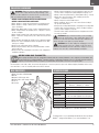 3
3
-
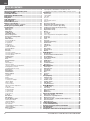 4
4
-
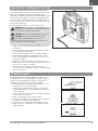 5
5
-
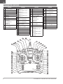 6
6
-
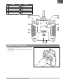 7
7
-
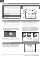 8
8
-
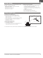 9
9
-
 10
10
-
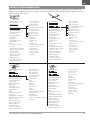 11
11
-
 12
12
-
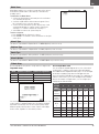 13
13
-
 14
14
-
 15
15
-
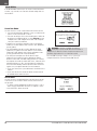 16
16
-
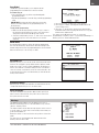 17
17
-
 18
18
-
 19
19
-
 20
20
-
 21
21
-
 22
22
-
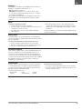 23
23
-
 24
24
-
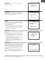 25
25
-
 26
26
-
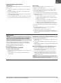 27
27
-
 28
28
-
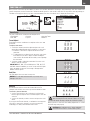 29
29
-
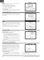 30
30
-
 31
31
-
 32
32
-
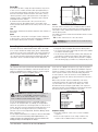 33
33
-
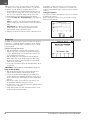 34
34
-
 35
35
-
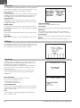 36
36
-
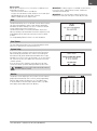 37
37
-
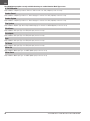 38
38
-
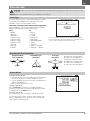 39
39
-
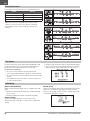 40
40
-
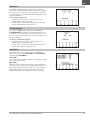 41
41
-
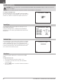 42
42
-
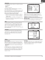 43
43
-
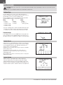 44
44
-
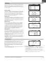 45
45
-
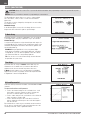 46
46
-
 47
47
-
 48
48
-
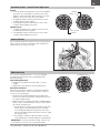 49
49
-
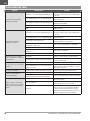 50
50
-
 51
51
-
 52
52
-
 53
53
-
 54
54


Spektrum NX10 10 Channel Transmitter Only Owner's manual
- Category
- Remote controlled toys
- Type
- Owner's manual
- This manual is also suitable for
Ask a question and I''ll find the answer in the document
Finding information in a document is now easier with AI
Related papers
-
Spektrum SPMR10110 Owner's manual
-
Spektrum SPMR7100 Owner's manual
-
-
Spektrum TM1100 DSMX Fly-By Aircraft Telemetry Module Operating instructions
-
Spektrum NX8 8 Channel DSMX Transmitter Only User manual
-
E-flite EFL12550UC Owner's manual
-
Spektrum DX8 Owner's manual
-
Spektrum NX6 6 Channel Transmitter Only User manual
-
Spektrum DX8eDX8e 8-Channel Transmitter Only Owner's manual
-
Spektrum DX4e DSMX 4-Channel Full Range Tx only MD1/3 Owner's manual
Other documents
-
Blade BLH5450 Owner's manual
-
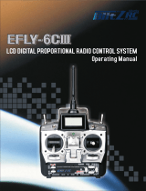 BlitzRCWorks EFLY-6CIII Specification
-
Blade ST-10+ User manual
-
RadioLink T6EAP User manual
-
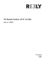 Reely HT-6 User manual
-
Fly Sky FS-i6X User manual
-
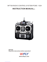 WFLY WFT08 User manual
-
Blade BLH6150 Owner's manual
-
Aircraft Extras FPS-Plus-nt Installation guide
-


