Bradford White 54367 Installation guide
- Category
- Space heaters
- Type
- Installation guide

Information contained in this document is subject to change without notice.
1
238-54367-00A REV 09/21
INSTALLATION GUIDE AND OWNER’S MANUAL
KwickShot® Tankless Electric Water Heaters
Read and understand the instructions thoroughly before attempting the installation or service of the water heater. Failure
to follow the instructions can result in serious injury, death and/or property damage. The warranty of the water heater will
depend upon proper installation according to the instructions. Some heaters come supplied with separate faucet aerators.
If supplied, the aerator must be installed in the faucet for optimum performance. The heater must only be used to heat
water and must be installed in a location where it is not subject to freezing temperatures. The manufacturer is not liable for
any damages resulting from improper installation or misuse.
The installation must conform to the latest requirements of the National Electrical Code and all applicable state and local
codes. This information is available through local authorities. You must fully understand the requirements before
beginning this installation.
This water heater is not required by UL 499 to employ a temperature and pressure relief valve (T&P). Check with local
codes to find out if one is required. If it is, the T&P valve must be installed in the outlet hot water pipe between the heater
and the isolation valve.
IMPORTANT SAFETY INSTRUCTIONS
When using electrical equipment, basic safety precautions should always be followed, including the following:
READ AND FOLLOW ALL INSTRUCTIONS
Supply the water heater only from a grounded system. A green terminal (or a wire connector marked “G”, “GR, “Ground”,
or “GROUNDING”) is provided for wiring the appliance. To reduce the risk of electric shock, connect this terminal, or
connector, to the grounding terminal of the electric service or supply panel with a continuous copper wire. Connection
should be made in accordance with the electrical installation code.
BEFORE ATTEMPTING ANY INSTALLATION, MODIFICATION OR SERVICE OF THE
HEATER, MAKE SURE THE ELECTRICAL POWER IS DISCONNECTED.

Information contained in this document is subject to change without notice.
2
238-54367-00A REV 09/21
DO NOT INSTALL IN A BATH ENCLOSURE OR SHOWER STALL OR CONNECT TO A SALT-REGENERATED
WATER SOFTENER OR A WATER SUPPLY OF SALT WATER. ATTENTION: NE PAS INSTALLER DANS UNE BAIGNOIRE OU UNE
CABINE DE DOUCHE ET NE PAS BRANCHER À UN ADOUCISSEUR D’EAU RÉGÉNÉRÉ AVEC DU SEL OU À UN
APPROVISIONNEMENT EN EAU SALÉE.
(CANADIAN INSTALLATIONS ONLY) CONNECT ONLY TO A CIRCUIT PROTECTED BY A CLASS A GROUND
FAULT CIRCUIT INTERRUPTER. ATTENTION: BRANCHER UNIQUEMENT À UN CIRCUIT PROTÉGÉ PAR UN DISJONCTEUR DE
FUITE DE TERRE DE CLASSE A.
(CANADIAN INSTALLATIONS ONLY) USE COPPER CONDUCTORS ONLY. USE BONDING CONDUCTOR IN
ACCORDANCE WITH THE CANADIAN ELECTRICAL CODE PART I. UTILISEZ DEZ CONDUCTEURS EN CUIVE UNIQUEMENT.
UTILISEZ DES CONDUCTEURS DE MIZE À LA MASSE CONFORMEMENT AU CODE CANADIEN DE L’ÉLECTRICITÉ, PARTIE I.
Contents
1. GENERAL ............................................................................................................................................................................. 2
2. MOUNTING THE UNIT TO THE WALL .................................................................................................................................. 3
3. PLUMBING HOOK-UP .......................................................................................................................................................... 4
4. ELECTRICAL HOOK-UP ......................................................................................................................................................... 7
5. COMMISSIONING THE HEATER ........................................................................................................................................... 9
6. THERMOSTATIC UNIT OPERATION .................................................................................................................................... 11
7. TROUBLESHOOTING .......................................................................................................................................................... 13
8. PERIODIC MAINTENANCE .................................................................................................................................................. 15
9. REPLACEMENT PART NUMBERS ........................................................................................................................................ 15
10. REPAIR PARTS .................................................................................................................................................................... 16
SAVE THESE INSTRUCTIONS
SECTION 1: GENERAL
Bradford White offers thermostatic, and flow controlled tankless electric water heaters.
KwickShot® thermostatic heaters are designed to accept cold or preheated water and heat it to temperatures suitable for
normal domestic usage up to a maximum temperature setpoint of 140°F.

Information contained in this document is subject to change without notice.
3
238-54367-00A REV 09/21
“ML” option models: Factory set to a maximum temperature setpoint of 110°F and are recommended for multi-lavatory
handwashing applications – refer to section 3 for supplied aerator details.
“CA” option models: Manufactured for Canadian market and it indicates evaluation and compliance to either Underwriters
Laboratories (UL) or Intertek (ETL) under CAN/CSA-C22.2 No. 64/No. 88.
KwickShot® flow-controlled heaters are designed to take in cold water and heat it to temperatures suitable for
handwashing and other fixed-flow applications.
NOTICE: KwickShot® tankless electric water heaters are tested @ 125 deg. per Department of Energy (DOE)
10CFR Part 430, Energy Conservation Program for Consumer Products.
To obtain optimum performance and energy savings, the water heater should be located as close as possible to the point-
of-use. The unit is supplied with compression rings and nuts suitable for direct coupling to 3/8” copper or PEX™ piping.
Do not use additional screwed fittings, pipe dope or Teflon tape – doing so will void the warranty. DO NOT SOLDER
PIPES WHILE THE UNIT IS INSTALLED as serious damage to the heater will result and the warranty will be voided
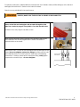
SECTION 2: MOUNTING THE UNIT TO THE WALL
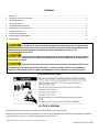
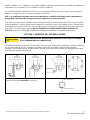
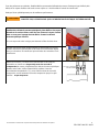
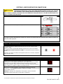
The heater should be mounted on the wall under the sink, as close to the point-of-use as possible. Ideal position is fittings
pointed down; however, the heater may be mounted in any orientation.
Note: an additional logo decal has been provided to ensure branding is clearly displayed in any mounting orientation.
Make sure to leave a minimum of 8 inches service
clearance at the end OPPOSITE the fittings.
THIS HEATER MUST BE INSTALLED IN A LOCATION WHERE IT IS NOT SUBJECT TO
FREEZING TEMPERATURES.

Information contained in this document is subject to change without notice.
4
238-54367-00A REV 09/21
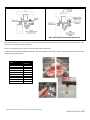
Remove the cover and fasten to the wall using the mounting holes at
each corner of the back plate. Replace the cover.
SECTION 3: PLUMBING HOOK-UP
The water heater is supplied with 3/8” brass compression fittings that are compatible with either copper or plastic pipes.
Make sure these fittings are used for this installation. Contact your representative for further information.
Bradford White strongly recommends that the heater be supplied directly from the main cold-water trunk line when
possible. This helps to avoid a potential water flow interruption to the water heater which could lead to a failure of the
heating element.
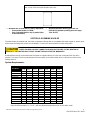
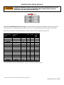
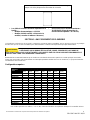
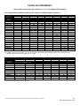
System Requirements:
Base Model*
Turn On Flow Rate, GPM (LPM)
0.2
(0.76)
0.25
(0.95)
0.3
(1.14)
0.4
(1.51)
0.5
(1.89)
0.7
(2.65)
0.8
(3.03)
TEF024V120
•
TEF030V120
•
TEF035V120
•
TEF035V240
•
TEF048V240
•
TEF055V240
•
TEF065V240
•
TEF075V240
•
TEF095V240
•
TEF030V208
•
TEF041V208
•
TET083V208
•
TEF030V277
•
TEF041V277
•
TEF060V277
•
TEF080V277
•
TEF090V277
•
TEF100V277
•
*Special suffixed models (i.e. CA, ML), will have identical temperature rises as their base model
• Minimum turn on flow rates are family dependent:
o Thermostatic Models: 0.2 GPM
o Flow Controlled Models: vary by model (refer
to the table below)
• Minimum/maximum working pressure: 30
PSI/150 PSI (Optimal operating pressure range:
35 to 80 PSI)
NEVER SUBSTITUTE THREADED PIPE FITTINGS USING PIPE DOPE OR TEFLON TAPE AND
NEVER SOLDER ANY PIPE CONNECTIONS WHILE ATTACHED TO THIS HEATER AS
DAMAGE TO THE HEATER WILL RESULT. DOING THIS WILL VOID THE WARRANTY!

Information contained in this document is subject to change without notice.
5
238-54367-00A REV 09/21
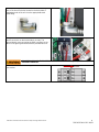
For optimum performance, Bradford White recommends the use of isolation valves (full flow ball type) on the inlet and
outlet pipes and a 40 mesh Y-Strainer on the inlet of the heater.
Clean the screen periodically for best performance.
BEFORE ATTEMPTING ANY INSTALLATION, MODIFICATION OR SERVICE OF THIS
HEATER, MAKE SURE THE ELECTRICAL POWER IS DISCONNECTED.
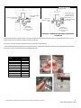
The heater’s water INLET and OUTLET are labeled. Install full flow ball
valves to the inlet and outlet pipes and run water through the inlet
pipe into a bucket to purge it of any debris. Close the inlet ball valve.
*Failure to do so may clog the inlet water screen.
Make sure the inlet filter screen is present in the inlet fitting and the inlet
and outlet pipes are correctly aligned with the heater connections to
minimize stress on the heater.
Remove the cover. Connect the pre-assembled inlet and outlet pipes to the
heater (do not overtighten compression fittings) and fully open the inlet
and outlet ball valves. Check the system for water leaks at all plumbing
connections. If a leak is present at the compression fitting, slowly tighten
compression nut until it stops – do not overtighten.

Information contained in this document is subject to change without notice.
6
238-54367-00A REV 09/21
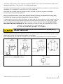
Sample installation diagrams:
Note: KwickShot® Thermostatic Models only
Open the hot water faucet and run water for a minimum of 60 seconds and until the flow is continuous and free of air pockets. Close
the faucet and install the aerator (if supplied).
Failure to install aerator will result in less-than-favorable heater performance.
**ML thermostatic models are designed to deliver a flow of 0.35 GPM to each lavatory. Please install the supplied aerators to ensure
maximum heating performance.
MODEL
# OF
AERATORS
TET055V240ML
2
TET060V277ML
2
TET065V240ML
2
TET075V240ML
2
TET080V277ML
2
TET083V208ML
3
TET090V277ML
3
TET095V240ML
3
TET100V277ML
3
TET115V240ML
3

Information contained in this document is subject to change without notice.
7
238-54367-00A REV 09/21
SECTION 4: ELECTRICAL HOOK-UP
BEFORE BEGINNING ANY WORK ON THIS INSTALLATION, CONFIRM THE ELECTRICAL
BREAKER IS “OFF” AND THAT ALL MOUNTING AND PLUMBING WORK HAS BEEN
COMPLETED PER THE STATED INSTRUCTIONS.
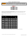
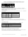
For use on an individual branch circuit only. The heater shall be installed using insulated, UL listed, 2 wire cable (2
wire plus ground) of the appropriate size suitable for up to 75°C and protected by the correctly rated circuit breaker.
Refer to the chart below for recommended copper wiring for conductors with a temperature rating of 75°C:
Flow Controlled
Models
Thermostatic
Models
Voltage
Max
power
Max
current
Minimum
wire size
(AWG)
@75°C
(VAC)
(kW)
(A)
TEF024V120
—
120
2.4
20
14
TEF030V120
—
120
3
25
12
TEF035V120
—
120
3.5
29
10
TEF035V240
—
240
3.5
15
14
TEF048V240
—
240
4.8
20
14
TEF055V240
TET055V240
240
5.5
23
12
TEF065V240
TET065V240
240
6.5
27
10
TEF075V240
TET075V240
240
7.5
32
10
TEF095V240
TET095V240
240
9.5
40
8
—
TET115V240
240
11.5
48
8
TEF030V208
—
208
3
15
14
TEF041V208
—
208
4.1
20
14
TEF083V208
TET083V208
208
8.3
40
8
TEF030V277
—
277
3
11
14
TEF041V277
—
277
4.1
14.8
14
TEF060V277
TET060V277
277
6
22
12
TEF080V277
TET080V277
277
8
29
10
TEF090V277
TET090V277
277
9
33
10
TEF100V277
TET100V277
277
10
36
8
*Recommendation for special suffixed models (i.e. CA, ML), are identical to standard models.

Information contained in this document is subject to change without notice.
8
238-54367-00A REV 09/21
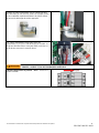
Power cable entry to the heater should be made through
one of the knock-out holes located on the back plate or
top/bottom ends of the unit. Use the appropriate strain
relief fitting.
The power leads are to be secured to the L1 and L2 or L
and N connectors on the terminal block or relay. The
ground lead is to be secured to the GND connector on the
block or the green ground wire with the provided wire nut.
FAILURE TO GROUND THE SYSTEM MAY RESULT IN SERIOUS INJURY, DEATH AND/OR
PROPERTY DAMAGE.
Leave the breaker in the “OFF” position. Proceed to the
next section:

Information contained in this document is subject to change without notice.
9
238-54367-00A REV 09/21
SECTION 5: COMMISSIONING THE HEATER
BEFORE SWITCHING THE ELECTRICAL BREAKER “ON”, VERIFY THE INLET AND OUTLET
BALL VALVES ARE FULLY OPEN AND WATER IS FLOWING THROUGH THE HOT WATER
FAUCET FOR A MINUTE OR TWO UNTIL THE FLOW IS CONTINUOUS AND FREE FROM AIR POCKETS. DO
NOT SWITCH THE BREAKER “ON” IF THERE IS A POSSIBILITY THE WATER IN THE HEATER IS FROZEN.
Verify water is flowing through the faucet.
Switch “ON” the electric power supply at the breaker.
The following steps are dependent on the water heater, please be sure to read all instructions to best commission the
appropriate model.
KwickShot® Flow Controlled Models
The LED indicator light will flash rapidly while water flows through the unit.
Maintain flow.
After 15 seconds, the LED indicator light will turn solid red and there will be an
audible click.
The heater is commissioned at this point. The faucet can be turned off and
used as needed.
Note: with no flow, the unit will flash every 4 seconds, indicating normal stand-
by mode.
KwickShot® Thermostatic Models
Keep water flowing through the faucet for the next step.
The display on the circuit board should come “ON”. With the flow running, the
heater will go through the 60 seconds startup/self-calibration procedure. The
display will count down from 60 to 0. When the display timer reaches 45, the
unit starts heating and continues counting down to 0.
After the 60 seconds in step 4, the display will show the temperature setpoint.
See The heater is commissioned at this point. Faucet can be turned off
and used as needed.
Note: the temperature display will turn off after 5 minutes of inactivity. Display
turns on when water flows through heater.

Information contained in this document is subject to change without notice.
10
238-54367-00A REV 09/21
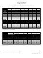
Congratulations!
Your KwickShot® tankless electric water heater is installed and ready for use!
For temperature rise at specified flow rate, please consult the table below:
Note: the values shown above are only for comparison purposes.
*Special suffixed models (i.e. CA, ML), will have identical temperature rises as their base model
“-” Flow rate below turn on flow for this model
BASE MODEL*
FLOW RATE, GPM (LPM)
KwickShot®
Thermostatic
models
0.35
(1.33)
0.5
(1.89)
1
(3.79)
1.5
(5.68)
2
(7.58)
2.5
(9.48)
3
(11.37)
TEMPERATURE RISE, °F (°C)
TET055V240
107**
(59)
75
(42)
38
(21)
25
(14)
19
(11)
15
(8)
13
(7)
TET065V240
127**
(71)
89
(49)
44
(24)
30
(17)
22
(12)
18
(10)
15
(8)
TET075V240
146**
(81)
102**
(57)
51
(28)
34
(19)
26
(14)
20
(11)
17
(9)
TET095V240
185**
(103)
130**
(72)
65
(36)
43
(24)
32
(18)
26
(14)
22
(12)
TET115V240
224**
(124)
157**
(87)
79
(44)
52
(29)
39
(22)
31
(17)
26
(14)
TET083V208
162**
(90)
113**
(63)
57
(32)
38
(21)
28
(16)
23
(13)
19
(11)
TET060V277
117**
(65)
82
(46)
41
(23)
27
(15)
20
(11)
16
(9)
14
(8)
TET080V277
156**
(87)
109**
(61)
55
(31)
36
(20)
27
(15)
22
(12)
18
(10)
TET090V277
176**
(98)
123**
(68)
61
(34)
41
(23)
31
(17)
25
(14)
20
(11)
TET100V277
195**
(108)
137**
(76)
68
(38)
46
(26)
34
(19)
27
(15)
23
(13)
**Note: the heaters’ actual temperature rises are limited by their thermostatic controls. The theoretical values shown above are only for
comparison purposes.
BASE MODEL*
KwickShot®
Flow
controlled
models
FLOW RATE, GPM (LPM)
0.2
(0.76)
0.25
(0.95)
0.3
(1.14)
0.4
(1.51)
0.5
(1.89)
0.7
(2.65)
0.8
(3.03)
1
(3.79)
TEMPERATURE RISE, °F (°C)
TEF024V120
82
(46)
66
(37)
55
(31)
41
(23)
33
(18)
23
(13)
20
(11)
16
(9)
TEF030V120
-
-
82
(46)
68
(38)
51
(28)
41
(23)
29
(16)
26
(14)
20
(11)
TEF035V120
-
-
-
-
80
(44)
60
(33)
48
(27)
34
(19)
30
(17)
24
(13)
TEF035V240
-
-
-
-
80
(44)
60
(33)
48
(27)
34
(19)
30
(17)
24
(13)
TEF048V240
-
-
-
-
-
-
82
(46)
66
(37)
47
(26)
41
(23)
33
(18)
TEF055V240
-
-
-
-
-
-
-
-
75
(42)
54
(30)
47
(26)
38
(21)
TEF065V240
-
-
-
-
-
-
-
-
-
-
63
(35)
55
(31)
44
(24)
TEF075V240
-
-
-
-
-
-
-
-
-
-
73
(41)
64
(36)
51
(28)
TEF095V240
-
-
-
-
-
-
-
-
-
-
-
-
81
(45)
65
(36)
TEF030V208
-
-
82
(46)
68
(38)
51
(28)
41
(23)
29
(16)
26
(14)
20
(11)
TEF041V208
-
-
-
-
-
-
70
(39)
56
(31)
40
(22)
35
(19)
28
(16)
TEF083V208
-
-
-
-
-
-
-
-
-
-
81
(45)
71
(39)
57
(32)
TEF030V277
-
-
82
(46)
68
(38)
51
(28)
41
(23)
29
(16)
26
(14)
20
(11)
TEF041V277
-
-
-
-
-
-
70
(39)
56
(31)
40
(22)
35
(19)
28
(16)
TEF060V277
-
-
-
-
-
-
-
-
82
(46)
59
(33)
51
(28)
41
(23)
TEF080V277
-
-
-
-
-
-
-
-
-
-
78
(43)
68
(38)
55
(31)
TEF090V277
-
-
-
-
-
-
-
-
-
-
-
-
77
(43)
61
(34)
TEF100V277
-
-
-
-
-
-
-
-
-
-
-
-
-
-
68
(38)

Information contained in this document is subject to change without notice.
11
238-54367-00A REV 09/21
SECTION 6: KwickShot® THERMOSTATIC MODEL OPERATION
Factory temperature setpoints/maximum adjustable range:
KwickShot®
Thermostatic
models
Default
Setpoint
(°F)
Minimum
Setpoint
(°F)
Maximum
Setpoint
(°F)
Base Model
<4kW
105
70
140
>4kW
120
ML (Multi Lavatory)
110
70
110
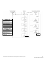
CHANGING SETPOINT TEMPERATURE
To INCREASE temperature, tap the “+” button repeatedly, or hold the “+” down to INCREASE the temperature quickly. To
DECREASE temperature, tap the “–” button repeatedly, or hold the “–” down to DECREASE the temperature quickly.
ADVANCED FUNCTIONS
With the display showing the current setpoint temperature, press BOTH “+” AND “–” buttons simultaneously for 3 seconds.
Screen Info
Title
Units
Description
Flow Rate
FLO
GPM or LPM
Current water flow rate through unit
Inlet temperature
IN
°F or °C
Cold water temperature
Outlet temperature
OUT
°F or °C
Hot water temperature
Power Factor
PF
%
How hard the heater is working
Software Revision
SR
-
For Technical Support assistance
Hold “-” to display the current screen title.
Press “+” to advance to the next screen.
Holding both “+” and “–” at any time for 3 seconds returns the display to the temperature set point, or just let the heater
return to set point display on its own after a period of time.
ERROR CODES & UNITS
From Advanced Menu, press and hold the “+” and “–” buttons for 10 seconds.
Screen Info
Title
Description
Current Error(s)
CE
Any errors currently present (F0 displays if no errors are present)
Past Errors
PE
Previous 5 errors and faults
Units
UN
Choose between °F/GPM and °C/LPM
Eco Mode*
ECO
Toggle non-silent operation
* Thermostatic models only
Pressing “-” at any time will display screen title (CE, PE1-5, UN, ECO).
Press the “+” button for 1 second to cycle through the following screens:
To return to setpoint hold “+” and “–” for 10 seconds, or just let the heater return to setpoint display or display turn-off on
its own after a period of time.

Information contained in this document is subject to change without notice.
12
238-54367-00A REV 09/21

Information contained in this document is subject to change without notice.
13
238-54367-00A REV 09/21
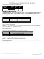
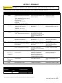
SECTION 7: TROUBLESHOOTING
ENSURE POWER TO THE UNIT IS “OFF” BEFORE REMOVING THE PROTECTIVE COVER
FOR ANY REASON.
For status resolution, please consult the table for your heater model below.
KwickShot® Thermostatic models
Code
Name
Possible causes
Heater response
Possible solutions
F23
No heat
- element failure
- ECO tripped/malfunctioning
- triac(s) failed open
- relay/contactor malfunctioning
- control board failure
- inlet water supply out of spec
Heating will be disabled after 30
seconds of continuous no heat
condition.
- measure element resistance
with the unit completely turned off
F24
Low heat
- undervoltage
- triac(s) failed open
- control board failure
- inlet/outlet thermistor(s) failure
Heating enabled, reduced
performance (lower outlet
temperature).
- verify power supply (voltage)
while heater is running
F33
Residual heat
- internal water temperature elevated
without flow
- both triacs failed closed
Heating disabled until outlet
temperature falls below the
reactivation temperature (see
default parameters table).
- run water through the unit
F34
Overvoltage
- inlet voltage is too high compared to
the stated heater specifications
Heating enabled, reduced
performance (higher outlet
temperature).
- have certified personnel verify
the inlet voltage
- provide voltage within specified
range
F36
Undervoltage
- inlet voltage is too low compared to
the stated heater specifications
Heating enabled, reduced
performance (lower outlet
temperature).
- have certified personnel verify
the inlet voltage
- provide voltage within specified
range
F38
High flow
- flow is too high to heat the water to
setpoint temperature
Heating enabled; unit operates
as intended (lower outlet
temperature possible).
- reduce flow (outlet flow
restrictor, faucet aerator)
F47
Inlet
thermistor
failure
- inlet thermistor interrupted or
disconnected
Heating enabled based on
default inlet temperature setting
(see default parameters table;
higher/lower outlet temperature
possible).
- inspect connections/wiring of
inlet thermistor
F48
Outlet
thermistor
failure
- outlet thermistor interrupted or
disconnected
Heating enabled; auto calibration
disabled.
- inspect connections/wiring of
outlet thermistor
F64
Freeze
warning
- inlet temperature is too low (below
35°F)
Heating disabled while condition
is present.
- increase inlet water temperature
above 35°F
Status code
Model suffix
Default values
F33
T, ML
Trip
170°F
Reactivation
140°F
KwickShot® Thermostatic models

Information contained in this document is subject to change without notice.
14
238-54367-00A REV 09/21
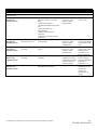
KwickShot® Flow controlled models
LED Pattern
Status/Problem
Possible causes
Heater response
Possible solutions
Solid light
Heating
N/A
N/A
N/A
One flash every four
seconds
Idle
N/A
- unit waits for flow
N/A
Two flashes once,
three second pause
Low heat
- outlet temperature below 90°F/32°C
for 5 seconds of flow
- element failure
- ECO tripped/malfunctioning
- relay/contactor malfunctioning
- control board failure
- inlet water supply out of spec
- unit keeps running,
LED flashes a warning
pattern
- reduce flow through
unit
Two flashes twice,
three second pause
Outlet thermistor failure
- outlet thermistor interrupted or
disconnected
- unit keeps running,
LED flashes a warning
pattern
- inspect
connections/wiring of
outlet thermistor
Two flashes three
times, three second
pause
Over-temperature
Warning
- outlet temperature exceeds
110°F/38°C
- unit keeps running,
LED flashes a warning
pattern
-increase flow through
unit. If this
temperature is desired
no action is required
Three flashes once,
three second pause
Over-temperature
Protection
- outlet temperature exceeds
150°F/65°C
- unit stops heating until
outlet temperature falls
below preset minimum
- increase flow through
unit to decrease the
overall temperature
rise
Three flashes twice,
three second pause
Freeze warning
- inlet temperature is too low (below
35°F/2°C)
- heating disabled
- increase temperature
of inlet water to meet
product specifications

Information contained in this document is subject to change without notice.
15
238-54367-00A REV 09/21
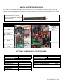
SECTION 8: PERIODIC MAINTENANCE
The heater is designed for many years of carefree use. In order to maintain consistent water flow, it may be necessary to periodically
clean the faucet aerator, or the filter screen located in the brass inlet fitting at the heater.
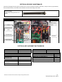
Element cartridge
installs inside heating chamber of all
heaters
SECTION 9: REPLACEMENT PART NUMBERS
KwickShot® Flow controlled models
KwickShot® Thermostatic models
Triacs
COMPRESSION FITTINGS
3/8” NUT
EX68B
3/8” SLEEVE
EX68C
AERATORS
0.35 GPM
EX0061-0.3-AER
0.5 GPM
EX0061-0.5-AER
Energy Cut-Off (ECO)
KwickShot® Thermostatic
models (Base, ML)
EX278A-KIT
KwickShot® Flow controlled
models (Base)
EX278A-KIT
CA
EX08100-03-KIT
PLUMBING ADAPTORS
MALE 13/16"-27 X MALE 55/64"-27
EX61-339
FEMALE 3/4"-27 X MALE 55/64"-27
EX61-341
FEMALE 13/16"-24 X MALE 55/64"-27
EX61-349
MALE 15/16"-27 X MALE 55/64"-27
EX61-336
MALE 11/16"-27 X MALE 55/64"-27
EX61-344
MALE M24X1/FEMALE M22X1 X MALE 55/64"-27
EX61-387
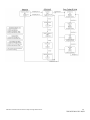
Contactor
Triacs
Heating chamber
Relay
Control board
Terminal block
Electrical cut-off
(ECO)

Information contained in this document is subject to change without notice.
16
238-54367-00A REV 09/21
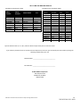
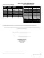
KwickShot® Thermostatic models
MODEL
NUMBER*
ELEMENT
CARTRIDGE
CONTROL BOARD
RELAY
TET055V240
EX1050
EX384-240
EX255B
TET065V240
EX890
EX384-240
EX255B
TET075V240
EX770
EX384-240
EX255B
TET090V240
EX630
EX384-240
EX255B
TET115V240
EX500 PRT
EX384-240
EX1050-1
TET083V208
EX520
EX384-240
EX255B
TET060V277
EX1280
EX384-277
EX253B
TET080V277
EX960
EX384-277
EX253B
TET090V277
EX850
EX384-277
EX253B
TET100V277
EX760
EX384-277
EX253B
KwickShot® Flow controlled models
MODEL
NUMBER*
ELEMENT
CARTRIDGE
CONTROL
BOARD
RELAY
TEF024V120
EX610
EX383
EX250B
TEF030V120
EX480
EX383
EX250B
TEF035V120
EX410
EX383
EX250B
TEF035V240
EX1650
EX383
EX254
TEF048V240
EX1200
EX383
EX254
TEF055V240
EX1050
EX383
EX254
TEF065V240
EX890
EX383
EX254
TEF075V240
EX770
EX383
EX255B
TEF095V240
EX630
EX383
EX255B
TEF030V208
EX1440
EX383
EX254B
TEF041V208
EX1050
EX383
EX254B
TEF083V208
EX520
EX383
EX255B
TEF030V277
EX260
EX383
EX251B
TEF041V277
EX1870
EX383
EX251B
TEF060V277
EX1280
EX383
EX251B
TEF080V277
EX960
EX383
EX251B
TEF090V277
EX850
EX383
EX253B
TEF100V277
EX760
EX383
EX253B
*Special suffixed models (i.e. CA, ML), will have identical replacement parts as their base model.
If you need any assistance from our Technical Service Department, make sure you can identify this water heater by having the
following numbers from your unit:
Model Number: __________________________________
Serial Number: ___________________________________
Bradford White Corporation
200 Lafayette Street
Middleville, MI 49333
800-334-3393
SECTION 10: REPAIR PARTS

Les informations contenues dans le présent document peuvent être modifiées sans préavis.
1
238-54367-00A RÉV 09/21
GUIDE D'INSTALLATION ET MANUEL D'UTILISATION
Chauffe-eau électriques sans réservoir KwickShot®
Lisez et comprenez attentivement les instructions avant de tenter l'installation ou l'entretien du chauffe-eau. Le non-
respect des instructions peut entraîner des blessures graves, la mort et/ou des dommages matériels. La garantie du
chauffe-eau dépendra d'une installation normale selon les instructions. Certains appareils de chauffage sont fournis avec
des aérateurs de robinet séparés. S'il est fourni, l'aérateur doit être installé dans le robinet pour une performance
optimale. Le chauffe-eau ne doit être utilisé que pour chauffer de l'eau et doit être installé dans un endroit où il n'est pas
soumis à des températures de congélation. Le fabricant n'est pas responsable des dommages résultant d'une mauvaise
installation ni d'une mauvaise utilisation.
L'installation doit être conforme aux dernières exigences du Code national de l'électricité et à tous les codes nationaux et
locaux applicables. Ces informations sont disponibles auprès des autorités locales. Vous devez bien comprendre les
exigences avant de commencer cette installation.
Ce chauffe-eau n'est pas tenu par la norme UL 499 d'utiliser une soupape de décharge et de sécurité (T&P). Vérifiez
auprès des codes locaux pour savoir si une est nécessaire. Si c'est le cas, la soupape T&P doit être installée dans le
tuyau de sortie d'eau chaude entre le chauffe-eau et la soupape d'isolement.
CONSIGNES DE SÉCURITÉ IMPORTANTES
Lors de l'utilisation d'équipements électriques, des précautions de sécurité de base doivent toujours être suivies,
notamment les suivantes :
LIRE ET SUIVRE TOUTES LES INSTRUCTIONS
N'alimentez le chauffe-eau qu'à partir d'un système mis à la terre. Une borne verte (ou un connecteur de fil marqué « G »,
« GR », « Terre » ou « MISE À LA TERRE ») est fournie pour le câblage de l'appareil. Pour réduire le risque de choc
électrique, connectez cette borne, ou connecteur, à la borne de mise à la terre du service électrique ou du panneau
d'alimentation avec un fil de cuivre continu. Le raccordement doit être effectué conformément au code d'installation
électrique.
AVANT DE TENTER TOUTE INSTALLATION, MODIFICATION OU ENTRETIEN DU
CHAUFFE-EAU, ASSUREZ-VOUS QUE L'ALIMENTATION ÉLECTRIQUE EST
DÉBRANCHÉE.
AVERTISSEMENT

Les informations contenues dans le présent document peuvent être modifiées sans préavis.
2
238-54367-00A RÉV 09/21
NE PAS INSTALLER DANS UNE CABINE DE BAIN OU UNE CABINE DE DOUCHE, NI CONNECTER À UN ADOUCISSEUR
D'EAU RÉGÉNÉRÉ AU SEL NI À UNE ALIMENTATION EN EAU SALÉE. ATTENTION : NE PAS INSTALLER DANS UNE BAIGNOIRE OU UNE CABINE
DE DOUCHE ET NE PAS BRANCHER À UN ADOUCISSEUR D’EAU RÉGÉNÉRÉ AVEC DU SEL OU À UN APPROVISIONNEMENT EN EAU SALÉE.
(INSTALLATIONS CANADIENNES UNIQUEMENT) CONNECTEZ UNIQUEMENT À UN CIRCUIT PROTÉGÉ PAR UN
DISJONCTEUR DE FUITE DE TERRE DE CLASSE A. ATTENTION : BRANCHER UNIQUEMENT À UN CIRCUIT PROTÉGÉ PAR UN DISJONCTEUR DE
FUITE DE TERRE DE CLASSE A.
(INSTALLATIONS CANADIENNES UNIQUEMENT) UTILISER UNIQUEMENT DES CONDUCTEURS EN CUIVRE. UTILISEZ UN
CONDUCTEUR DE LIAISON CONFORMÉMENT AU CODE CANADIEN DE L’ÉLECTRICITÉ PARTIE I. UTILISEZ DES CONDUCTEURS EN CUIVE
UNIQUEMENT. UTILISEZ DES CONDUCTEURS DE MIZE À LA MASSE CONFORMEMENT AU CODE CANADIEN DE L’ÉLECTRICITÉ, PARTIE I.
Table des matières
1. GÉNÉRALITÉS ....................................................................................................................................................................... 2
2. MONTAGE DE L'APPAREIL AU MUR .................................................................................................................................... 3
3. RACCORDEMENT DE PLOMBERIE ........................................................................................................................................ 4
4. BRANCHEMENT ÉLECTRIQUE .............................................................................................................................................. 7
5. MISE EN SERVICE DU CHAUFFE-EAU ................................................................................................................................... 9
6. FONCTIONNEMENT DE L'UNITÉ THERMOSTATIQUE ..................................................................................................... 11
7. DÉPANNAGE ...................................................................................................................................................................... 13
8. ENTRETIEN PÉRIODIQUE ................................................................................................................................................... 15
9. NUMÉROS DE PIÈCES DE RECHANGE ................................................................................................................................ 15
10. PIÈCES DE RÉPARATION .................................................................................................................................................... 16
CONSERVEZ CES INSTRUCTIONS
SECTION 1 : GÉNÉRALITÉS
Bradford White propose des chauffe-eau électriques sans réservoir thermostatiques et à débit contrôlé.
Les chauffe-eau thermostatiques KwickShot® sont conçus pour accepter de l'eau froide ou préchauffée et la chauffer à
des températures adaptées à un usage domestique normal jusqu'à une température de consigne maximale de 140 °F.
Modèles en option « ML » : réglés en usine à un point de consigne de température maximum de 110 °F et sont
recommandés pour les applications de lavage des mains à plusieurs lavabos. Reportez-vous à la section 3 pour les
détails de l'aérateur fourni.
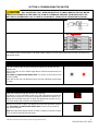
MISE EN GARDE
MISE EN GARDE
MISE EN GARDE
Une température d'eau supérieure à 52 °C (125°F) peut causer
instantanément des brûlures graves ou mortelles.
Les enfants, les personnes handicapées et celles d'un âge
avancé courent le plus grand risque de brûlures.
Relisez ce manuel d'instructions avant de régler la temperature
du chauffe-eau.
Testez au toucher la température de l'eau avant le bain ou la
douche.
Des valves de limitation de température sont disponibles.

Les informations contenues dans le présent document peuvent être modifiées sans préavis.
3
238-54367-00A RÉV 09/21
Modèles en option « CA » : fabriqués pour le marché canadien et indiquent l'évaluation et la conformité aux Underwriters
Laboratories (UL) ou Intertek (ETL) sous CAN/CSA-C22.2 No. 64/No. 88.
Les chauffe-eau à débit contrôlé KwickShot® sont conçus pour aspirer de l'eau froide et la chauffer à des températures
adaptées au lavage des mains et à d'autres applications à débit fixe.
AVIS : Les chauffe-eau électriques sans réservoir KwickShot® sont testés à 125 degrés selon le Department of
Energy (DOE) 10CFR Part 430, Energy Conservation Program for Consumer Products.
Pour obtenir des performances optimales et des économies d'énergie, le chauffe-eau doit être situé le plus près possible
du point d'utilisation. L'unité est fournie avec des bagues de compression et des écrous adaptés pour un couplage direct
à une tuyauterie en cuivre ou PEX™ de 3/8 po. N'utilisez pas de raccords vissés supplémentaires, de pâte à joint ou de
ruban téflon, car cela annulera la garantie. NE PAS SOUDER LES TUYAUX PENDANT QUE L'APPAREIL EST
INSTALLÉ car de graves dommages à l'appareil de chauffage en résulteraient et la garantie serait annulée
SECTION 2 : MONTAGE DE L'APPAREIL AU MUR
Le chauffe-eau doit être monté sur le mur sous l'évier, aussi près que possible du point d'utilisation. La position idéale est
les raccords pointés vers le bas ; cependant, le chauffe-eau peut être monté dans n'importe quelle orientation.
Remarque : un autocollant de logo supplémentaire a été fourni pour garantir que la marque est clairement affichée dans
n'importe quelle orientation de montage.
Assurez-vous de laisser un espace de service d'au moins
8 pouces à l'extrémité OPPOSÉE aux raccords.
CE CHAUFFE-EAU DOIT ÊTRE INSTALLÉ DANS UN ENDROIT OÙ IL N'EST PAS SOUMIS
À DES TEMPÉRATURES DE CONGÉLATION.
MISE EN GARDE
8 po de dégagement
8 po de dégagement

Les informations contenues dans le présent document peuvent être modifiées sans préavis.
4
238-54367-00A RÉV 09/21
Retirez le couvercle et fixez-le au mur à l'aide des trous de montage à
chaque coin de la plaque arrière. Remettez le couvercle.
SECTION 3 : RACCORDEMENT DE PLOMBERIE
Le chauffe-eau est fourni avec des raccords à compression en laiton de 3/8 po compatibles avec les tuyaux en cuivre ou en plastique.
Assurez-vous que ces raccords sont utilisés pour cette installation. Contactez votre représentant pour plus d'informations.
Bradford White recommande fortement que le chauffe-eau soit alimenté directement à partir de la conduite principale d'eau froide
lorsque cela est possible. Cela permet d'éviter une interruption potentielle du débit d'eau vers le chauffe-eau, ce qui pourrait entraîner
une défaillance de du chauffe-eau.
Configuration requise :
Modèle de
base*
Activer le débit, GPM (LPM)
0,2
(0,76)
0,25
(0,95)
0,3
(1,14)
0,4
(1,51)
0,5
(1,89)
0,7
(2,65)
0,8
(3,03)
TEF024V120
•
TEF030V120
•
TEF035V120
•
TEF035V240
•
TEF048V240
•
TEF055V240
•
TEF065V240
•
TEF075V240
•
TEF095V240
•
TEF030V208
•
TEF041V208
•
TET083V208
•
TEF030V277
•
TEF041V277
•
TEF060V277
•
TEF080V277
•
TEF090V277
•
TEF100V277
•
*Les modèles spéciaux avec suffixe (c.-à-d. CA, ML) auront des élévations de température identiques à leur modèle de base
• Les débits d'activation minimum dépendent de la
famille :
o Modèles thermostatiques : 0,2 GPM
o Modèles à débit contrôlé : varient selon le
modèle (consultez le tableau ci-dessous)
• Pression de service minimum/maximum :
30 PSI/150 PSI (Plage de pression de
fonctionnement optimale : 35 à 80 PSI)
NE JAMAIS REMPLACER LES RACCORDS DE TUYAUTERIE FILETÉS PAR DE LA PÂTE
LUBRIFIANTE OU DU RUBAN TÉFLON ET NE JAMAIS SOUDER LES RACCORDS DE
TUYAUTERIE LORSQU'ILS SONT ATTACHÉS À CE CHAUFFE-EAU CAR CELA POURRAIT ENDOMMAGER LE
CHAUFFE-EAU. FAIRE CELA ANNULERA LA GARANTIE !
MISE EN GARDE
Page is loading ...
Page is loading ...
Page is loading ...
Page is loading ...
Page is loading ...
Page is loading ...
Page is loading ...
Page is loading ...
Page is loading ...
Page is loading ...
Page is loading ...
Page is loading ...
-
 1
1
-
 2
2
-
 3
3
-
 4
4
-
 5
5
-
 6
6
-
 7
7
-
 8
8
-
 9
9
-
 10
10
-
 11
11
-
 12
12
-
 13
13
-
 14
14
-
 15
15
-
 16
16
-
 17
17
-
 18
18
-
 19
19
-
 20
20
-
 21
21
-
 22
22
-
 23
23
-
 24
24
-
 25
25
-
 26
26
-
 27
27
-
 28
28
-
 29
29
-
 30
30
-
 31
31
-
 32
32


Bradford White 54367 Installation guide
- Category
- Space heaters
- Type
- Installation guide
Ask a question and I''ll find the answer in the document
Finding information in a document is now easier with AI
in other languages
Related papers
-
Bradford White 54368 User manual
-
Bradford White ES-3500-4-S-10 User manual
-
-
-
-
-
Bradford White Everhot IGE-199C Series User manual
-
Bradford White IGI-180R User manual
-
-
Bradford White TGHE-160E-N(X) User manual
Other documents
-
Bradford-White Corp ES-3500 User manual
-
EemaX SPEX2412T DI Installation guide
-
EemaX EX60T Installation guide
-
EemaX SP48 User guide
-
-
HTP Crossover Residential Floor Water Heater Installation guide
-
-
-
Westinghouse WGRGH20LP75F User manual
-
Rheem 5450, 6450, 8450 Owner's manual