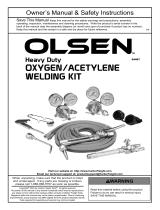
Sealey SGA2.V2 Operating instructions

Type
Operating instructions

The Sealey SGA2.V2 is a versatile and reliable welding and brazing kit, perfect for a variety of metalworking tasks. With its durable construction and easy-to-use design, the SGA2.V2 is ideal for both professional and DIY enthusiasts.

The SGA2.

The Sealey SGA2.V2 is a versatile and reliable welding and brazing kit, perfect for a variety of metalworking tasks. With its durable construction and easy-to-use design, the SGA2.V2 is ideal for both professional and DIY enthusiasts.

The SGA2.

OXYACETYLENE WELDING & BRAZING KIT
MODEL NO: SGA2.V2 & SGA6.V2
Thank you for purchasing a Sealey product. Manufactured to a high standard, this product will, if used according to these instructions,
and properly maintained, give you years of trouble free performance.
IMPORTANT: PLEASE READ THESE INSTRUCTIONS CAREFULLY. NOTE THE SAFE OPERATIONAL REQUIREMENTS, WARNINGS & CAUTIONS. USE
THE PRODUCT CORRECTLY AND WITH CARE FOR THE PURPOSE FOR WHICH IT IS INTENDED. FAILURE TO DO SO MAY CAUSE DAMAGE AND/OR
PERSONAL INJURY AND WILL INVALIDATE THE WARRANTY. KEEP THESE INSTRUCTIONS SAFE FOR FUTURE USE.
1. SAFETY
9 Always have a fire extinguisher nearby.
9 Never use oxygen or fuel gas to blow soot or dirt from your clothes.
8 DO NOT wear ragged clothes, as sparks can ignite the ragged or loose ends.
9 Always wear goggles or a helmet with the appropriate shade lens.
8 DO NOT use shaded safety spectacles or unshaded face shield visors for cutting or welding. They DO NOT stop the harmful rays which
cause eye damage.
9 Use gauntlet type gloves made from heat resistant material.
9 Secure cylinders to a trolley, wall or post to prevent them from falling.
9 All cylinders should be used and stored in an upright position.
9 Never drop or strike a cylinder. DO NOT use cylinders that have been dented.
9 Cylinder caps should be used when storing or moving cylinders.
9 Empty cylinders should be kept in specified areas and clearly marked ‘EMPTY’.
8 DO NOT use oil or grease on any inlet connections, outlet connections or cylinder valves.
Keep all threads and unions clean and free from
oil, dirt or grease.
9 Examine hoses for cuts, burns or worn areas before each use. Also inspect fittings for damage. If any damage is found, replace
immediately.
8 DO NOT repair hose with tape.
9 Always use reverse flow check valves on torch and flashback arrestors on the regulator. This greatly reduces the possibility of mixing
gases in the regulator or hoses. Reverse flow check valves are an important safety precaution.
9 Working pressure on an acetylene regulator should NEVER be set above 15psi (1 bar).
9 These instructions cover the use of the kits on mild steel. If used on any other materials, extra precautions will have to be
taken.
9 Make sure that there is a good flow of air to the user and the tip, at all times. Use a welding fume extractor if conditions are poor or space is
confined.
8 DO NOT leave the torch alight and unattended.
9 For safety advice regarding gas bottles (oxygen and acetylene) refer to the supplier of the bottles.
9 Make sure bottle keys are in place at all times so that in the event of an emergency the valves can be turned off quickly.
9 Keep hoses away from flame at all times. Make sure that hoses are laid flat where possible and not in a position where they can be run
over by vehicles, which would result in permanent damage.
WARNING! LEAKING HOSES CAN KILL. Leak test all connections and valves prior to each use of the equipment. Ensure hose
fittings are sufficiently tightened to the torch, We recommend to tighten both joints at the same time using two spanners to offer counter
resistance whilst applying sufficient pressure to tighten all connections to ensure no leaks and no damage to the torch.
9 If hoses are not long enough, join them together with the manufacturer’s couplings only.
8 DO NOT join damaged hoses, they must be replaced immediately.
9 Remember at all times BLUE = OXYGEN ‘O
RED = ACETYLENE ‘A
8 At no time may you interchange parts contained in this kit with those of other manufacturers.
9 Only Sealey replacement items should be used.
9 Acetylene fittings have a left-handed thread and notches on hose unions to indicate this.
2. INTRODUCTION
SGA2.V2: Welding torch supplied with mixer nozzle and no’s: 2,5, and 10 nozzles.
SGA6.V2: Cutting torch, welding torch, no’s: 2, 5 and 120 lightweight welding nozzles, 1/16”, 3/64” ANMS cutting nozzles.
Y
SGA2.V2, SGA6.V2 Issue:2 (1,4) 10/08/21
Original Language Version
© Jack Sealey Limited
Refer to
instruction
manual
Wear gloves Wear
protective
clothing
Wear
opaque eye
protection
3. CONTENTS
4. PREPARATION
WARNING! DANGER OF EXPLOSION. All parts which come into contact with acetylene or oxygen, including hands and tools, must be
free from oil or grease. If grease or oil is found on a cylinder, discontinue its use immediately and contact your gas supplier.
4.1. Preparing the cylinder. Make sure that the cylinder to be used is safe and properly secured as noted in the safety precautions.
4.2. Whilst standing on one side ‘crack’ each cylinder valve. ‘Cracking’ is to quickly open and close the valve allowing gas to escape and
clear the valve of any foreign bodies.
4.3. CONNECTING GAS REGULATORS TO THE CYLINDERS
NOTE: PRESSURE REGULATORS SHOULD BE TREATED AS PRECISION INSTRUMENTS AND SHOULD NOT BE JARRED
OR KNOCKED.
4.3.1. Function of the regulators. Fitted to the outlets of the gas cylinder valves, the pressure regulators reduce the pressure of the gas
from cylinder pressure to the constant lower pressure required for the operation of the equipment. The left hand gauge indicates the
pressure in the cylinder. The right hand gauge indicates the pressure of the gas being delivered to the torch. Pressure reduction
within the regulator occurs in two stages.
4.3.2. Attach oxygen and acetylene regulators to the appropriate cylinders. On each gauge ensure the inlet filter is in place and is not
blocked or contaminated. If an ‘0’ ring is fitted to the inlet, check for damage and replace if necessary with an ‘0’ ring recommended
by the regulator manufacturer. Do not use any form of jointing paste or tape between regulators and cylinder valves. Before
attaching the gauges wipe the fittings with a clean dry cloth. Screw the union at the base of each regulator to the appropriate
cylinder by hand. Ensure that the gauge is correctly orientated so as to be seen properly by the operator in use. To tighten, turn
CLOCKWISE for OXYGEN, and ANTI-CLOCKWISE for ACETYLENE. A wrench should be used to ensure tight connections.
4.3.3. Close the regulators by turning the adjusting screws anti-clockwise to relieve the pressure on the diaphragm before opening the
cylinder valve. If this is not done, pressure from the cylinder can damage the diaphragm and render the regulator inoperative.
1 Welding torch
2 No:2 nozzle
3 No:3 nozzle
4 No:4 nozzle
5 1/16” cutting nozzle
6 3/64” cutting nozzle
7 1/32” cutting nozzle
8 Cutting torch
9 Nozzle cleaning tools
SGA2
SGA6
Original Language Version
© Jack Sealey Limited
Fig.1
Fig.1A
SGA2.V2, SGA6.V2 Issue:2 (1,4) 10/08/21
4.3.4. The cylinder valve-to-regulator connection should be checked for leaks using an approved leak detection spray or soap and water
solution.
4.4. CONNECTING FLASH ARRESTORS AND HOSES TO THE GAS REGULATORS
4.4.1. Connect a BLUE colour coded, OXYGEN flash arrestor to the outlet on the OXYGEN regulator. (As shown above, on the left).
4.4.2. Then, connect a BLUE colour coded hose to the BLUE, OXYGEN flash arrestor. (As shown above, on the left).
4.4.3. Connect a RED colour coded, ACETYLENE Flash arrestor to the outlet on the ACETYLENE regulator. (As shown above, on the right).
4.4.4. Then, connect a RED colour coded hose to the RED, ACETYLENE flash arrestor.(As shown above, on the right).
4.4.5. Tighten all nuts securely with a wrench. If any sign of oil or grease is found on the flash arrestors or regulators discontinue use
immediately.
Note: New hoses contain a preservative powder which must be blown out before use.
4.4.6. Prior to attaching the torch, blow out both hoses to eliminate any particles or debris. Perform this on one hose at a time and in a well
ventilated area, otherwise you may create conditions for fire or explosion.
a. Turn the oxygen or acetylene regulator adjusting screw clockwise to allow 5psi to pass through hose.
b. Allow oxygen or acetylene to flow for approximately 10 seconds to purge each hose in turn.
4.5. ASSEMBLING THE TORCH FOR WELDING. (SGA2 & SGA6)
WARNING! The teflon seal on the welding attachment inlet must not be damaged or missing, otherwise gases will mix inside the torch
and result in flashbacks or backfires. Always inspect the seal, coupling nut and torch head for damage or oil. If either is found, discontinue
use and contact your supplier.
4.5.1. Screw the chosen welding nozzle into the welding attachment making sure that it is fully tightened down.
4.5.2. Screw the welding attachment with nozzle attached onto the torch handle as shown below. Before fully tightening the ribbed nut,
check that the orientation of the gas valve knobs suits your normal welding practice. Adjust if necessary and fully tighten the ribbed nut.
NOTE:
THE REGULATORS SHOWN HERE ARE NOT SUPPLIED WITH THE SGA2 OR SGA6 BUT ARE SHOWN HERE TO ILLUSTRATE
THE REGULATORS REQUIRED FOR A TYPICAL WELDING AND CUTTING SET UP.
Original Language Version
© Jack Sealey Limited
Fig.2
SGA2.V2, SGA6.V2 Issue:2 (1,4) 10/08/21
4.6. ASSEMBLING THE TORCH FOR CUTTING. (SGA6 ONLY)
WARNING! The teflon seal on the cutting attachment inlet must not be damaged or missing, otherwise gases will mix inside the
torch and result in flashbacks or backfires. Always inspect the seal, coupling nut and torch head for damage or oil. If either is found,
discontinue use and contact your supplier.
4.6.1. To change the cutting nozzle loosen and remove the nut which holds it in place and withdraw the nozzle. Slide the chosen cutting nozzle
through the nut and screw the assembly into the cutting attachment and fully tighten down.
4.6.2. Screw the cutting attachment with nozzle attached onto the torch handle as shown below. Before fully tightening the the ribbed nut, adjust
the orientation of the gas valve knobs so that they do not block the movement of the lever (B).
4.7. CONNECTING NON-RETURN VALVES AND HOSES TO THE TORCH.
4.7.1. Always fit non-return valves (not supplied) to the torch before connecting the respective hoses. Non-return valves have different direction
threads to ensure that they are fitted to the correct side of the torch. An OXYGEN non-return valve has a normal thread and will fit to the
blue coded side of the torch (See colour coding on valve knobs). An ACETYLENE non-return valve has a reverse thread and will fit to the
red coded side of the torch (See colour coding on valve knobs).
4.7.2. Connect the two hoses (not supplied) to the respective non-return valves fitted to the torch handle.
WARNING! Ensure hose fittings are sufficiently tightened to the torch, We recommend to tighten both joints at the same time using
two spanners to offer counter resistance whilst applying sufficient pressure to tighten all connections to ensure no leaks and no damage
to the torch.
WARNING! If traces of oil or grease are found, DO NOT use. Contact your gas supplier immediately.
5. WELDING
IMPORTANT. LEAK TEST ALL CONNECTIONS AND VALVES PRIOR TO EACH USE OF THE EQUIPMENT.
Note: These instructions are intended to describe the facilities and operation of the welding/cutting torch. They are not intended to
teach you how to weld or cut using oxyacetylene. If you have no experience of welding/cutting using oxyacetylene it is
essential that you seek training from a qualified person or approved training organisation.
5.1. Assemble the torch for welding as described in section 4.5 (See also fig.2)
5.2. SETTING THE GAS REGULATOR PRESSURES
5.2.1. Close the regulators by turning the adjusting screws anti-clockwise to relieve the pressure on the diaphragm before opening the cylinder
valves. Slowly open the cylinder valve on the oxygen and acetylene bottles in turn. As you do so the high pressure gauge (left hand) on
each regulator will register the pressure in the cylinder to which it is attached.
5.2.2. Slowly open each regulator in turn by turning the adjusting knob clockwise. As you do so the outlet pressure gauge (right hand) on
each regulator will register the outlet pressure of gas being fed to the torch. Adjust the pressure according to the size of nozzle in
use and the thickness of the material to be cut or welded. Refer to section 8 overleaf.
WARNING! Never set acetylene regulator at a delivery pressure above 15psi (1 bar).
5.2.3. After adjusting the regulators check for leaks at all connections. If a leak is found, tighten fitting more securely. If leak persists, discontinue use
and call your supplier.
5.2.4. Briefly open and close the oxygen valve on the torch handle to check that the gas is flowing.
5.2.5. Similarly open and close the acetylene valve on the torch handle to check that the gas is flowing.
WARNING! Always use welding gloves and suitable eye protection when welding or cutting. Contact your local Sealey stockist for a
full range of protective equipment.
5.3. LIGHTING THE TORCH Ensure that the gas hoses will not be in the way of the torch when ignited. Ensure that the torch is facing
away from you before lighting.
5.3.1. Holding the torch in one hand and the striker in the other open the acetylene valve a 1/4 turn (the valve knob is colour coded red).
Operate the striker close to the tip to light the acetylene.
5.3.2. The first flame that appears will be an orange/yellow colour giving off a small amount of black smoke from its tip. If too much acetylene is
flowing the flame will be standing away from the tip of the torch making a roaring noise. In extreme cases this type of flame can blow itself
out. To correct such a flame reduce the amount of acetylene until the flame is 8 to 10 inches long with less black smoke.
5.3.3. Once the acetylene flame is set correctly begin to introduce oxygen by slowly opening the oxygen control valve on the torch (The
valve knob is colour coded blue). The flame will change to a whitish colour and the black smoke will disappear. This flame is not hot
enough for welding.
5.3.4. Add more oxygen to the flame by further opening the control knob until a brilliant neutral flame is achieved.
5.4. SHUTTING DOWN AND LEAVING SAFE
5.4.1. Turn off the acetylene valve on the torch first and then turn off the oxygen valve a few moments later. Note: Turning the gases off in
the wrong order can cause damage to the torch.
5.4.2. Close both cylinder valves.
5.4.3. Drain gas from oxygen regulator by opening the oxygen valve on the torch handle. Similarly drain gas from the acetylene regulator.
5.4.4. Release the adjusting knobs on the regulators. This is done by turning them anti-clockwise.
Original Language Version
© Jack Sealey Limited
Fig.3
SGA2.V2, SGA6.V2 Issue:2 (1,4) 10/08/21
6. CUTTING
IMPORTANT. LEAK TEST ALL CONNECTIONS AND VALVES PRIOR TO EACH USE OF THE EQUIPMENT.
Note: These instructions are intended to describe the facilities and operation of the welding/cutting torch. They are not intended to
teach you how to weld or cut using oxyacetylene. If you have no experience of welding/cutting using oxyacetylene it is
essential that you seek training from a qualified person or approved training organisation.
6.1. Assemble the torch for cutting as described in section 4.6 (See also fig.3)
6.2. GAS CONTROL WHEN USING THE CUTTING SET-UP
6.2.1. The control of the oxygen and acetylene flows on a cutting set-up differs from a welding set-up in the following ways:
The oxygen control valve on the torch handle should be fully opened so that regulation of the oxygen flow takes place using only the
oxygen control valve on the cutting attachment (see fig.3A).
6.2.2. The flow of the acetylene is still controlled by the red coded knob on the torch handle.
6.2.3. The flame is then set up using these two control valves only.
6.2.4. Once the flame is set additional oxygen can be introduced into the centre of the flame to initiate the cutting process by operating the
oxygen control lever (see fig.3B) mounted on the cutting attachment.
6.3. SETTING THE GAS REGULATOR PRESSURES
6.3.1. Close the regulators by turning the adjusting screws anti-clockwise to relieve the pressure on the diaphragm before opening the cylinder
valves. Slowly open the cylinder valve on the oxygen and acetylene bottles in turn. As you do so the high pressure gauge (left hand) on
each regulator will register the pressure in the cylinder to which it is attached.
6.3.2. Slowly open each regulator in turn by turning the adjusting knob clockwise. As you do so the outlet pressure gauge (right hand) on each
regulator will register the outlet pressure of gas being fed to the torch. Adjust the pressure according to the size of nozzle in use and the
thickness of the material to be cut . Refer to the chart in section 8.
WARNING! Never set acetylene regulator at a delivery pressure above 15psi (1 bar).
6.3.3. After adjusting the regulators to the desired operating pressures check connections for leaks using an approved leak detection solution.
Check for leaks at all connections. If a leak is found, tighten fitting more securely. If leak persists, discontinue use and call your supplier.
6.3.4. Briefly open and close the acetylene valve on the torch handle to check that the gas is flowing.
6.3.5. Ensure that the oxygen control valve on the cutting attachment is closed.
6.3.6. Fully open the oxygen control valve on the torch handle.
6.3.7. Briefly open and close the oxygen control valve on the cutting attachment to check that the gas is flowing.
6.3.8. Briefly operate the oxygen control lever on the cutting attachment to check that the gas is flowing from the centre of the cutting nozzle.
WARNING! Always use welding gloves and suitable eye protection when welding or cutting. Contact your local Sealey dealer for a full
range of protective equipment.
6.4. LIGHTING THE TORCH
6.4.1. Ensure that the gas hoses will not be in the way of the torch when ignited. Ensure that the torch is facing away from you before lighting.
6.4.2. Holding the torch in one hand and the striker in the other open the acetylene valve on the torch handle a 1/4 turn (the valve knob is
colour coded red). Operate the striker close to the tip to light the acetylene.
6.4.3. The cutting tip has six separate holes in it arranged radially and each of these holes will have a small flame coming from it. Develop
the correct flame at each hole by alternately increasing the flow of acetylene and then oxygen until a neutral flame is achieved at each
hole having a white cone about an 1/8” long.
6.5. USING THE OXYGEN CONTROL LEVER
6.5.1. Use the pre-heat flame to heat the metal to be cut to a cherry red colour. When the metal reaches this stage press the oxygen control lever
to initiate the cutting process. This feeds additional oxygen through a central hole in the cutting tip. No flame is produced from this hole but the
pure oxygen reacts chemically with the hot metal causing it to oxidise i.e. burn away.
6.6. SHUTTING DOWN AND LEAVING SAFE
6.6.1. Turn off the acetylene valve on the torch first and then turn off the oxygen valve a few moments later. Note: Turning the gases off in
the wrong order can cause damage to the torch.
6.6.2. Close both cylinder valves.
6.6.3. Drain gas from oxygen regulator by opening the oxygen valve on the torch handle. Similarly drain gas from the acetylene regulator.
6.6.4. Release the adjusting knobs on the regulators. This is done by turning them anti-clockwise.
7. MAINTENANCE
7.1. Annual maintenance should be carried out by a person who has sufficient practical experience of oxyacetylene gas equipment and a
detailed theoretical knowledge of the functioning of the equipment, the properties of gases used and potential defects and hazards
which may occur and their importance to the integrity and safety of the equipment.
7.2. The chart shown below relates to Blowpipes. A similar maintenance schedule should be carried out in relation to Regulators,
Flashback Arrestors and Hose assemblies as laid down in the Code of Practice CP7 of the British Compressed Gases Association.
Equipment Maintenance
Each time
equipment is used
by the operator
Annual Replacement/
refurbishment
intervals
Replacement/
refurbishment
guideline
Blowpipes Visual examination of
the nozzle and inlet
seatings for damage.
Leak test all joints at
working pressure.
Test valve functions.
Blank exits and
leak test for internal
malfunctions.
Determined by local
operating conditions.
Replace with a new,
repaired or service
exchange unit.
Original Language Version
© Jack Sealey Limited SGA2.V2, SGA6.V2 Issue:2 (1,4) 10/08/21
Original Language Version
© Jack Sealey Limited
8. TECHNICAL INFORMATION
Cutting capacities
Operating pressure (bar - lbf/in²) Gas consumption (ltr/m - ft³/h)
Mild steel Nozzle size Oxygen Acetylene O2 - Cutting O2 -
Heating
Acetylene
6mm / 14” 1/32” 1.4 - 20 0.30 - 4 14.15 - 30 8.5 - 18 8.0 - 17
13mm / 1/2” 3/64” 2.1 - 30 0.35 - 5 30.70 - 65 10.4 - 22 9.4 - 20
25mm / 1” 1/16” 2.8 - 40 0.40 - 6 67.50 - 143 13.2 - 28 11.8 - 25
50mm / 2” 1/16” 3.1 - 4.5 0.40 - 6 78.30 - 166 13.2 - 28 11.8 - 25
75mm / 3” 1/16” 3.5 - 50 0.40 - 6 88.70 - 188 13.2 - 28 11.8 - 25
Welding capacities
Operating pressure (bar - lbf/in²) Gas consumption (ltr/m - ft³/h)
Mild steel Nozzle size Oxygen Acetylene O2 - Cutting O2 -
Heating
Acetylene
1.2mm / 18SWG LW02 0.14 - 2 0.14 - 2 11.8 - 25 4.2 - 9 38.8 - 8
2.6mm / 12SWG LW05 0.28 - 4 0.21 - 3 23.5 - 50 4.2 - 9 38.8 - 8
4mm / 8SWG LW10 0.35 - 5 0.28 - 4 56.6 - 120 4.2 - 9 38.8 - 8
SGA2.V2, SGA6.V2 Issue:2 (1,4) 10/08/21
Sealey Group, Kempson Way, Suffolk Business Park, Bury St Edmunds, Suffolk. IP32 7AR
01284 757500 01284 703534 sales@sealey.co.uk www.sealey.co.uk
Note: It is our policy to continually improve products and as such we reserve the right to alter data, specifications and component parts without prior
notice. Please note that other versions of this product are available. If you require documentation for alternative versions, please email or call
our technical team on technical@sealey.co.uk or 01284 757505.
Important: No Liability is accepted for incorrect use of this product.
Warranty: Guarantee is 12 months from purchase date, proof of which is required for any claim.
ENVIRONMENT PROTECTION
Recycle unwanted materials instead of disposing of them as waste. All tools, accessories and packaging should be sorted, taken to
a recycling centre and disposed of in a manner which is compatible with the environment. When the product becomes completely
unserviceable and requires disposal, drain any fluids (if applicable) into approved containers and dispose of the product and fluids
according to local regulations.
  • Page 1 1
  • Page 2 2
  • Page 3 3
  • Page 4 4
  • Page 5 5
  • Page 6 6

Sealey SGA2.V2 Operating instructions

Type
Operating instructions

The Sealey SGA2.V2 is a versatile and reliable welding and brazing kit, perfect for a variety of metalworking tasks. With its durable construction and easy-to-use design, the SGA2.V2 is ideal for both professional and DIY enthusiasts.

The SGA2.

Ask a question and I''ll find the answer in the document

Finding information in a document is now easier with AI