Page is loading ...

Enclosure 3X Pressure Switches Page i
NEO-DYN
MODELS 100P, 101P, 110P, 180P, 200P, 201P
ADJUSTABLE PRESSURE SWITCHES;
MODEL 160P
ADJUSTABLE DIFFERENTIAL PRESSURE SWITCHES,
ENCLOSURE 3X FOR WEATHERPROOF APPLICATIONS
INSTALLATION AND
OPERATION MANUAL
PN 610-0008 Rev D

Page ii Installation and Operation Manual
WARNING
CAUTION
NOTE
Manual No. 610-0008 Rev D
Neo-Dyn
28150 Industry Drive
Valencia, CA 91355
Tel: (661) 295-4000
Fax: (661) 294-1750
World Wide Web: www.neodyn.com
Copyright 2002
ITT Industries
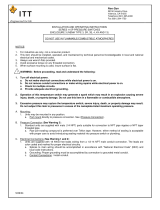
Important Information
The product warranty applicable to this ITT Neo-Dyn®
instrument is as stated on page 18 of this manual.
Should any after-delivery problems arise, please contact
ITT Neo-Dyn’s Customer Service using the information above.
Our normal business hours are weekdays, 7:00 am to 3:30 PM,
Pacific Time.
Before installing this pressure switch, become familiar with the
installation and adjustment instructions in Chapters 2 and 3.
Indicates a hazard which can cause severe personal injury,
death, or substantial property damage if the warning is
ignored.
Indicates a hazard which will or can cause minor personal injury
or property damage if the caution is ignored.
Indicates additional information about a particular item necessary
to the operation of the unit.
This document contains proprietary information, which is the
property of Neo-Dyn, a unit of ITT Industries. This document
may not be reproduced, either in part or in full, without the
consent of ITT Industries.

Enclosure 3X Pressure Switches Page iii
TABLE OF CONTENTS
PAGE
CHAPTER 1 INTRODUCTION ................................................. 1
CUSTOMER SERVICE ............................................................ 3
OTHER CONFIGURATIONS .................................................. 3
CHAPTER 2 INSTALLATION .................................................. 4
MOUNTING ............................................................................. 4
PROCESS CONNECTIONS ..................................................... 5
PROCESS MEDIA .................................................................... 6
ELECTRICAL CONNECTIONS .............................................. 6
CHAPTER 3 ADJUSTMENTS AFTER INSTALLATION ....... 8
SETPOINT ADJUSTMENT ..................................................... 8
CHAPTER 4 TROUBLESHOOTING ....................................... 10
CHAPTER 5 SPECIFICATIONS .............................................. 12
STANDARD ........................................................................... 12
OPTIONS ................................................................................ 17
WARRANTY INFORMATION ................................................. 18


Enclosure 3X Pressure Switches Page 1
CHAPTER
1
INTRODUCTION
The Neo-Dyn® Enclosure 3X Switches described in this manual
are weather-proof, electromechanical sensing devices designed for
a wide range of applications in pneumatic and hydraulic systems
up to 10,000 psig. Models 100P, 101P, 110P, 200P, and 201P are
gauge pressure switches, Model 180P is a vacuum switch, and
Model 160P is a differential pressure switch.
The most common wetted materials of these pressure and vacuum
switches include a polyimide (Kapton) sensing diaphragm, nitrile
O-ring, and aluminum alloy or corrosion resistant steel (CRES)
pressure port. CRES diaphragms and all-welded constructions are
also available in some models for corrosive pressure media and
are standard on the temperature switches.
Setpoint adjustments are easily made through the adjustable range
by turning an adjustment nut located inside the housing. On
Models 101P and 201P this adjustment is external.
The standard configuration of these switches will switch up to 15
amp at up to 250 VAC in a single-pole configuration, and up to
11 amp at up to 250 VAC in a double-pole configuration. When
ordered with M Option, the switch is rated for currents to one
amp, but its bifurcated gold contacts will reliably switch currents in
the milliampere and microampere ranges.
These switches have CE Mark, and they all have weatherproof
enclosures with IP66 ingress protection and that meet the
requirements of NEMA 3. 3R, 3S, 4, 4X and 13. The internal
switch elements are UL and CSA recognized components.

Page 2 Installation and Operation Manual
Figure 1: Models 100P, 101P, 110P, 160P, 180P,
200P, 201P: Enclosure 3X Adjustable Pressure Switches
(Pressure Port Configurations Vary with Model and Range)
Hidden lines indicate mounting holes under the cover (see page 4).
The following models use the Alternate Conduit Fitting Location:
100P and 101P, Range 1; 110P, 160P, 180P
Chapter 5 on page 12 contains complete specifications for these
Adjustable Pressure Switches.
ADJUSTMENT
KNOB,
MODELS
101P, 201P
PRESSURE
PORT
CONDUIT FITTING, 1/2-14 NPT FEMALE
ALTERNATE LOCATION (SEE BELOW)
CONDUIT FITTING
1/2-14 NPT FEMALE
STANDARD LOCATION
(SEE BELOW)
HOUSING COVER
4X COVER SCREW
LOW-PRESSURE PORT, MODELS 152P, 160P
VACUUM PORT, MODEL 180P
1/4-18 NPT FEMALE

Enclosure 3X Pressure Switches Page 3
WARNING
CUSTOMER SERVICE
If you have any questions about these Pressure Switches that are
not covered in this manual, you can contact Neo-Dyn or our
representatives in several ways.
The Neo-Dyn customer service phone number is
(661) 295-4000. Our customer service department is open
from 7:00 am to 3:30 p.m. Pacific Time.
Our Internet site is www.neodyn.com; it includes lists of
sales representatives and distributors.
OTHER CONFIGURATIONS
The models described in this manual are also available in special
and factory-set configurations. For these units, follow the
installation and operating instructions herein, except adhere to
the pressure and electrical limits marked on the units.

Page 4 Installation and Operation Manual
WARNING
WARNING
WARNING
WARNING
CHAPTER
2
INSTALLATION
Installation of these Neo-Dyn
®
Enclosure 3X pressure switches is
straightforward. However, they must be installed by a qualified
electrician, in compliance with all local and national electrical codes.
Electrical Hazard
Do not make electrical connections while power is on.
Always check for multiple circuits.
Always make sure grounding is adequate.
MOUNTING
The Pressure Switch can be mounted directly to the process
connection if there is no significant vibration and the fluid lines
are capable of supporting the weight. It can also be attached to a
flat surface, such as a wall or panel, using .250 in. diameter or M6
socket-head cap screws through the mounting holes that are
accessed by removing the housing cover; allow .5 in. (12.7 mm)
screw length above the mounting surface. These holes are located
on two corners of a 2.72 inch (6.91 cm) square, or 3.85 inches
(9.77 cm) apart on a 45° diagonal.
Note that on certain models and ranges the housing of the pressure
fitting has a large outside diameter that extends below the
mounting surface, requiring either a cutout in that surface, or
having the pressure fitting overhang an edge. These models are
100P and 101P, Range 1; 110P; 142P; 152P; 160P; and 180P.

Enclosure 3X Pressure Switches Page 5
CAUTION
WARNING
PROCESS CONNECTIONS
The process connections are:
Models 160P and 180P, both ports: ¼” - 18 NPT female standard.
On Model 180P, the vacuum port is on the side of the round
housing, and the normal pressure port must be left open to the
atmosphere, which serves as the reference pressure.
All other pressure switches:
Wetted Material 1: ¼” - 18 NPT female standard
Wetted Materials 4-9: ½” - 14 NPT female standard
In addition, some pressure switches can be ordered with Option E
(7/16”-20 SAE port); refer to part numbering in Chapter 5
When installing the Pressure Switch, always:
Make sure that the unit and your system have matching threads.
Use the wrench flats provided.
Seal all joints with pipe joint sealing compound.
Avoid excessive torque on all threaded connections.
Do not exceed the marked Maximum Operating Pressure in
normal operation.
The marked Proof Pressure is provided to give the maximum
allowable pressure without causing permanent damage to the
pressure switch in the event of an over-pressure condition. Set
pressure relief/safety valves below this setting.

Page 6 Installation and Operation Manual
NOTE
WARNING
PROCESS MEDIA
Process media must be compatible with the wetted materials listed
in Chapter 5 starting on page Error! Bookmark not defined..
Compatibility is defined by an “A” rating in the Chemical
Resistance Guide for Metals and Alloys, the Chemical Resistance
Guide for Plastics, and the Chemical Resistance Guide for
Elastomers, all published by Compass Publications, and available
from the National Association of Corrosion Engineers (NACE),
Houston, Texas; telephone 281 228-6200.
ELECTRICAL CONNECTIONS
An internal terminal block is standard, with a green screw for
attaching the ground wire. See Figure 2 and Figure 3.
All field wiring must comply with requirements of the NEC or
applicable local or national electrical codes, including wire
gauges and insulation temperature ratings. Conduit seals may
be required.
Figure 2. Form C and CC Schematics Shown Below the
Decreasing Setpoint
The direction of increasing pressure shown above represents the
direction of increasing vacuum on Model 180P.
RED NC1
BRN C1
BLU NO1
BLK NC2
YEL C2
VIO NO2
GRN
SCREW
RED NC1
BRN C1
FORM CC FORM C
GRN
SCREW

Enclosure 3X Pressure Switches Page 7
NOTE
Figure 3. Form Z Schematic Shown
Below the Decreasing Setpoint
The direction of increasing pressure shown above represents the
direction of increasing vacuum on Model 180P.
NC BLK
GRN
SCREW
NO VIO
RED NC
BLU NO

Page 8 Installation and Operation Manual
CHAPTER
3
ADJUSTMENTS AFTER
INSTALLATION
The factory-set setpoint or adjustable setpoint range is marked on
the nameplate of the switch. This section describes the
adjustments needed after an Adjustable Pressure Switch has been
properly installed.
SETPOINT ADJUSTMENT
Disconnect the electrical power. Check for multiple circuits.
1. On all models except 101P and 201P, loosen the screws on
the housing cover, and move it aside.
2. Check the setpoints per paragraphs 4 and 5 below for precise
adjustments.
3. The adjustment nut can be rotated by hand or with an open-
end wrench or similar tool (use a screwdriver on Models
101P and 201P, or turn the knob by hand if a knob is
included). The range scale is intended to be used only as an
approximate guide; it indicates the increasing setpoint.
4. To check the increasing setpoint, connect a pressure source
and a calibrated pressure gauge or transducer to the pressure
port and slowly apply increasing pressure (or vacuum on
Model 180P) until the switch actuates. Actuation can be
noted by listening to the audible snap of the Belleville spring,
or with an ohmmeter across the appropriate terminals in the
terminal block.

Enclosure 3X Pressure Switches Page 9
CAUTION
5. If you want to check the decreasing setpoint, slowly decrease
the pressure or vacuum after the switch has actuated and note
the value at which the audible snap or an ohmmeter indicates
deactuation. Deadband may be calculated if desired by
subtracting the decreasing setpoint reading from the
increasing setpoint reading.
6. On all models except 101P and 201P, replace the cover by
moving it back into position over the top of the housing and
tightening the screws until the cover is snug against its
gasket. Do not over tighten, as this could damage the gasket.

Page 10 Installation and Operation Manual
CHAPTER
4
TROUBLESHOOTING
In-service problems are unlikely, but the following paragraphs
suggest ways to verify any problems that might arise:
1. Pressure Switch Leaks
If a leak is suspected, isolate the pressure switch from the rest
of the system. Connect the switch and a calibrated pressure
gauge downstream from a pressure source and shutoff valve.
Apply normal system pressure, isolate the gauge and Pressure
Switch from the pressure source with the shutoff valve for at
least one minute, and check for leaks as evidenced by a drop
in the gauge reading.
If a leak is verified, return the unit for repair. Contact ITT
directly, or your local sales representative or distributor (see
www.neodyn.com for a contact list).
2. Failure to Switch
If application of pressure or vacuum 10% greater than the
adjusted setpoint fails to produce actuation, first check for
contamination in the process connection, and verify that the
expected pressure is reaching the sensing diaphragm or
piston, or temperature is reaching the temperature probe.
If the Belleville spring can be heard to audibly snap, but an
ohmmeter indicates no electrical switching, the cause is
probably stuck or burned switch contacts, or the switch
element has moved away from the position where it was
synchronized with the snap action. Return the unit for repair.

Enclosure 3X Pressure Switches Page 11
If application of pressure or vacuum 10% greater than the
adjusted setpoint fails to produce an audible snap of the
Belleville spring, there is probably a mechanical failure or
binding due to contamination. Return the unit for repair.
3. Calibration Shifts
If it is suspected that the setpoints have shifted, recheck them
per paragraphs 4 and 5 of Chapter 3. If you verify unstable or
drifting setpoints, return the unit for repair.

Page 12 Installation and Operation Manual
CHAPTER
5
SPECIFICATIONS
This section shows standard specifications and available options.
STANDARD
Interfaces
Weight: approximately 3 pounds (1.4 kg) each
Conduit Connection: ½” - 14 NPT female
Standard Pressure Port:
Wetted Material 1: ¼” - 18 NPT female
Wetted Materials 4-9: ½” - 14 NPT female
Models 160P (both ports) and 180P: ¼” - 18 NPT female
Listing Agency Approvals
Switch Elements UL and CSA recognized components
CE Mark All models
Internal switching elements are recognized components by both
UL and CSA.

Enclosure 3X Pressure Switches Page 13
Part Number
The part number contains information about which configurations
and options are included in your Adjustable Pressure Switch. To
determine the pressure range, electrical rating, and options,
compare the part number of your unit with the information in
Figure 4 below and the following tables.
100P 1 2 CC 3 BX
Model Series Options
Wetted Material Weather Proof
Range Number Elec. Form (C, CC, or Z)
Figure 4. Part Number Breakdown
Part number format varies for specials.
NOTE

Page 14 Installation and Operation Manual
Pressure Ratings - Models 100P and 101P
* See Figure 4 on page 13 for the part number breakdown
Table 1
Part No**
Range
No
Max Operating
Pressure,
psig (bar)
Proof Pressure
PSIG (bar)
100P*1*3X
1
600 (41.37)
1000 (68.95)
100P*2*3X
2
3000 (206.9)
5000 (344.8)
100P*4*3X
4
3000 (206.9)
5000 (344.8)
100P*5*3X
5
3000 (206.9)
5000 (344.8)
100P*7*3X
7
3000 (206.9)
5000 (344.8)
100P*8*3X
8
3000 (206.9)
5000 (344.8)
** Same part number format for Model 101P
Pressure Ratings - Model 110P
Table 2
Part No
Range
No
Max Operating
Pressure,
psig (bar)
Proof Pressure
PSIG (bar)
110P*2*3X
2
300 (20.69)
500 (34.48)
110P*4*3X
4
300 (20.69)
500 (34.48)
Pressure Ratings - Model 180P
Table 3
Part No
Range
No
Max Operating
Pressure,
psig (bar)
Proof Pressure
psig (bar)
180P*4*3X
4
225 (15.51)
350 (24.13)

Enclosure 3X Pressure Switches Page 15
Pressure Ratings - Models 200P and 201P
Table 4
Part No**
Range
No
Max Operating
Pressure,
psig (bar)
Proof Pressure
psig (bar)
200P12*3X
2
3000 (207)
4500 (310)
200P13*3X
3
7500 (517)
11250 (776)
200P16*3X
6
7500 (517)
11250 (776)
200P18*3X
8
10000 (690)
15000 (1034)
200P18*3EX
8
9500 (655)
15000 (1034)
** Same part number format for Model 201P
Pressure Ratings - Model 160P
Table 5
Part No
Range
No
Max Operating
Pressure,
psig (bar)
Proof Pressure
psig (bar)
160P*2*3X
2
300 (20.69)
500 (34.48) high / low;
200 (13.79) low / high
160P*4*3X
4
500 (34.48)
1000 (68.95) high / low;
400 (27.58) low / high
160P*6*3X
6
500 (34.48)
1000 (68.95) high / low;
400 (27.58) low / high
160P*7*3X
7
500 (34.48)
1000 (68.95) high / low;
400 (27.58) low / high

Page 16 Installation and Operation Manual
Weather Proof Ratings:
Ingress protection IP66
Enclosure type 3, 3R, 3S, 4, 4X, 13 (NEMA)
Temperature Ratings for Pressure Media
Standard (Nitrile O-rings, -40°C (-40°F) to +121°C (+250°F)
and Wetted Matl. 5-7, 9);
C Option (EPR O-rings):
B Option (Viton O-rings): -26°C (-15°F) to +121°C (+250°F)
and Kalrez O-rings
Wetted Material 8: Follows limits defined by O-rings
above; Kalrez is same as Viton
Electrical and Ambient Temperature Ratings
Minimum ambient temperature is -40 °C (-40 °F), except with
B Option and Kalrez O-rings it is -26°C (-15°F)
Form C3X (SPDT):
15 amp @ 125 or 250 VAC , 1/8 HP @ 125 VAC,
¼ HP @ 250 VAC, to +70 °C (+158 °F) max;
5 amp resistive , 3 amp inductive @ 28 VDC; .5 amp resistive ,
.04 amp inductive @ 125 VDC to +85 °C (+186 °F) max.
Form CC3X (DPDT):
11 amp* and ¼ hp @ 125 or 250 VAC to +65 °C (+149 °F) max;
5 amp resistive , 3 amp inductive @ 28 VDC; .5 amp resistive
@ 125 VDC to+85 °C (+186 °F) max.
Form C3MX or CC3MX (SPDT or DPDT with M Option):
1 amp @ 125 VAC to +85 °C (+186 °F) max.
Form Z3X (SPDT):
15 amp @ 125 or 250 VAC , 1/4 HP @ 125 VAC,
1/2 HP @ 250 VAC, to +80 °C (+176 °F) max;
5 amp resistive , 3 amp inductive @ 28 VDC; 1 amp resistive ,
.5 amp inductive @ 125 VDC to +85 °C (+186 °F) max.
/