SERVING THE GAS INDUSTRY WORLDWIDE
Bryan Donkin RMG Gas Controls Limited
GAS PRESSURE REGULATOR SERIES 280-309
Technical Description

GAS PRESSURE REGULATOR SERIES 280-309
2
Introduction
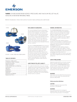
The Series 280-309 is a spring loaded, externally impulsed, high capacity regulator with integral safety cut-
off valve. The design incorporates a totally balanced, single ported valve which in conjunction with a
streamlined body ensures high flow capabilities.
A two-way vent valve ensures excellent speed of response combined with stable control.
Use with confidence on natural and manufactured gases of non-corrosive nature, including Nitrogen, Carbon
Dioxide, Propane and Butane.
Application
Designed for use on gas distribution systems and for services to industrial and commercial premises. Also
for industrial feeds to burners, heater units, boilers and other items of equipment, where an accurate, safe
and dependable pressure controlled system is required.
Features & Benefits
Balanced valve gives excellent pressure control.
Both regulator casing/valve head and safety cut-off valve can be removed from the body as cartridges,
reducing maintenance downtime.
Can be fitted with the Series 309 Overpressure (OPCO) or Under/Over pressure (UPCO/OPCO) Safety Cut-
Off Valve.
Valve travel indicator.
Regulator external control line fitted with fixed jet.
Positive lock-up under no flow conditions.
Safety Cut-Off Valve can be fitted with mirco-switch for remote indication (Optional extra)
Service Conditions:
SERVICE CONDITIONS
Model Outlet Pressure Range – mbarg Max. Inlet Pressure – barg
280H – 309 12 – 225 4.5
282H – 309 12 – 225 10.0*
284 – 309 140 – 1000 4.5
Temperature Range -20
o
C to + 60
o
C
Connections Flanged: PN16 - BS EN 1092-2: 1997
* Suitable for inlet pressures up to 8 barg – direct acting and 10.3 barg when fitted with an auxiliary control system.
Technical Data

GAS PRESSURE REGULATOR SERIES 280-309
3
REGULATOR: SERIES 280H/282H – 309LP REGULATOR: SERIES 284-309 MP2 OPCO
Spring Spring
Number Colour
Spring Range
mbarg
Number Colour
Spring Range
mbarg
548 Self 12 – 20 849 & 848 Red & Black 140 – 260
824 Lt. Green 18 – 35 851 & 850 Green & White 230 – 500
938 Lt. Blue 25 – 50 853 & 852 Yellow & Blue 460 - 1000
546 Grey 30 – 70
774 Brown 66 – 104
775 Orange 96 – 138
SAFETY CUT-OFF VALVE: 309 MP2 OPCO
778* Dark Blue 112 - 225 Spring
* requires special spring adjuster
Number Colour
Trip Range
barg
1132 White/Blue 0.5 – 0.8
SAFETY CUT-OFF VALVE: 309LP OPCO
1133 White/Red 0.7 – 1.1
Spring 1134 White/Grey 1.0 – 1.8
Number Colour
Trip Range
mbarg
1135 White/Brown 1.5 – 2.9
861 Brown 39 – 90
1103 Gold 80 – 130
1104 Purple 120 – 250
SAFETY CUT-OFF VALVE: 309 MP2 UPCO
1105 Black 200 – 350 1192 White/Purple
50 – 150 mbar
SAFETY CUT-OFF VALVE: 309LP UPCO/OPCO
Spring
TYPE
Number Colour
Trip Range
mbarg
1109 Grey 40 – 55
1110 Green 50 – 110
1111 Silver 110 – 200
OPCO
1140 Silver/Red 150 – 250
UPCO 1138 Blue/Green 10 - 30
Recommended Settings
• Minimum OPCO Setting is 35 mbarg or 10% above
Regulator setting, whichever is the higher.
• Minimum Differential Pressure between UPCO &
OPCO Setting is: 30 mbarg (LP), 45 mbarg (MP1) &
85 mbarg (MP2 & MP4).
• Minimum Reset Pressure UPCO/OPCO is: UPCO
Setting plus: 10 mbarg (LP), 45 mbarg (MP1) & 80
mbarg (MP2 & MP4).
Spring Selection & Materials of Construction
MATERIALS OF CONSTRUCTION
Regulator:
Body Ductile Iron to BSS EN 1563
Grade EN-GJS-400-18
Diaphragm Casing Aluminium Alloy: BS 1490
Grade LM4
Valve Orifice Stainless Steel: BS 970
Grade 416S21
Diaphragms Terylene Reinforced Nitrile
Rubber Pentane Resistant
Valve Seat Nitrile Rubber
‘O’ Rings Nitrile
Safety Cut-Off Valve (309LP)
Body Aluminium: BS 1490 Grd. LM6
Spindle Stainless Steel: BS 970
Grade 316 S31
Valve Aluminium: BS 1474
Grade 6082TF
Valve Seating Polyurethane
Diaphragm & ‘O’ Rings Nitrile
Spring Adjuster Brass: BS 2874 - Grade CZ 121
Spring Spring Steel: BS 5216
Grade HS3

GAS PRESSURE REGULATOR SERIES 280-309
4
Installation
The regulator may be mounted in any orientation to suit site conditions; moisture or debris must not ingress
the vent valves. For optimum performance the recommended position is in a horizontal pipeline with the
spring housing pointing vertically upwards.
Note: On some burner applications, where rapid changes in flow rate occur, it may be necessary to fit a
variable jet into the regulator impulse line to tune the regulator to the downstream system.
Capacities in SCMH, natural gas SG:0.6
INLET PRESSURE OUTLET PRESSURE
mbarg/Bar 15 mbar 26 mbar 50 mbar
50 100 90 -
75 130 150 150
100 280 200 220
150 330 370 330
200 420 450 400
250 470 510 410
350 - - 610
750 690 680 700
1.0 Bar 1200
1.5 Bar 1650
2.0 Bar 2000
3.0 Bar 2500
4.0 bar 2900
5.0 Bar 4100
6.0 Bar 4550
7.0 Bar 5200
8.0 bar 5400
NB: For Series 284-309 Capacities - Contact BD-RMG for details

GAS PRESSURE REGULATOR SERIES 280-309
5
SERIES 280H/282H – 309LP SERIES 284 – 309 MP2
All Dimensions in MM, # will be increased by 50mm when a Micro-Switch is fitted.
SECTIONAL ARRANGEMENT
Dimensions & Weights, Sectional Arrangement
KEY:
Inlet Pressure
Outlet Pressure
/