Hitachi 50EX20B Operating instructions
- Category
- LCD TVs
- Type
- Operating instructions
This manual is also suitable for

PROJECTIONCOLORTV
OPERATING GUIDE
IMPORTANT SAFEGUARDS
2-5
FIRST TIME USE
6-13
THE REMOTE CONTROL 14-22
EASY GRAPHIC GUIDE
23-37
USEFUL INFORMATION
INDEX 38-43

IMPORTANT
Your new HITACHI PROJECTION TV incorporates a host offeatures designed to give you excellent performance ifyou
follow the instructions in this manual. We recommend that you read the following instructions and "IMPORTANT
SAFEGUARDS" notice before turning on your TV set for the first time.
Follow all warnings and instructions marked on this television receiver.
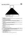
CAUTION
A ' RISK OF ELECTRIC SHOCK A
DO NOT OPEN
CAUTION:TO REDUCE THE RISK OF ELECTRICSHOCK,
DO NOT REMOVE COVER (OR BACK)
NO USER:SERVICEABLEPARTS INSIDE.
REFER SERVICING TO QUALIFIED SERVICE PERSONNEL
The lightningflashwitharrowheadsymbol,withinan
equilateraltriangle,isintendedtoalerttheusertothe
presenceof.uninsulated"dangerousvoltage"within
the product'senclosurethat may be of sufficient
magnitudeto constitutea risk of electricshockto
persons.
Theexclamationpointwithinanequilateraltriangleis
intendedtoalerttheusertothepresenceofimportant
operatingandmaintenance(sewicing)instructionsin
the literatureaccompanyingtheappliance.
WARNING:
TO PREVENT FIRE OR SHOCK HAZARD, DO NOT
EXPOSE THIS TELEVISION SYSTEM TO RAIN OR MOISTURE.
NOTE: • There are no user serviceable parts inside the receiver.
• Model number and eedal number are indicated on back side of the set.
CAUTION: Adjust onlythose controlsthat are covered inthe instructions,as improperchanges or modifications
not expressly approved by HITACHI could void the user's authority to operate the TV.
POWER SOURCE:
This HITACHI projection TV is designed to operate on 120 volts 60 Hz, AC household current.
Insert power cord into e 120 volt 60 Hz outlet.
TO PREVENT ELECTRIC SHOCK, DO NOT USE THE TELEVISION'S PLUG WiTH AN EXTENSION CORD,
RECEPTACLE, OR OTHER OUTLET UNLESS THE BLADES AND GROUND TERMINAL CAN BE FULLY
INSERTEDTO PREVENT BLADE EXPOSURE.
NEVER CONNECT THE I"V TO 50 Hz, DIRECT CURRENT, OR ANYTHING OTHER THAN THE SPECIFIED
VOLTAGE.
I NOTE: This television receiver will display television closed captioning, (r_l or I_), in accordance with
paragraph 15.119 of the FCC rules. •
,A cAUTION:
t
Neverremovethebackcoverofthesetasthiscanexposeyoutoveryhighvoltagesandother
hazards,ffthesetdoesnotoperateproperly,unplugthesetandcallyourdealerorserviceshop.
I
I

SAFETY TIPS
IMPORTANT SAFEGUARDS
CAUTION: SAFETY POINTSYOU SHOULD KNOWABOUT
" Read all o! these instructions YOUR HITACHI TELEVISION RECEIVER
* Save these instructions Ior later use.
* Follow all warnings and Instructions marked on the television receiver.
Our reputation has been built on the quality, performance, and ease ct service of HITACHI television receivers.
Safety is also foremost in our minds in the design of these units. To help you operate these products properly, this section illustrates safety tips which will be of benefit
to you. Please read it carefully and apply the knowledge you obtain from it to the proper operation of your HITACHI television receiver.
Please fill out your warranty card at once and mail it to HITACHI. This will enable HITACHI to notify you promptly in the improbable event that a safety problem should
be discovered in your model of product.
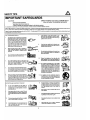
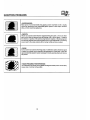
FOR YOUR PERSONAL SAFETY
1. This television set is equipped with a polarized
alternating-current line plug (a plug having one
blade wider than the other). This plug will fit into
the power outlet only one way. This is a safety
feature. Ifyou are unableto insert the plug fully
into the outlet, try reversing the plug. If the plug
should still fail to fit, contact your electrician to
replace your obsolete outlet. Do not defeat the
safety purpose of the polarized plug.
2. When the power cord or plug is damaged or _,a-_b
frayed, unplug this television set from the wall
outlet and refer servicing to qualified service
personnel.
3. Do not overload wall outlets and extension cords
as this can result in fire or electric shock.
8.
Do not allow anything to rest on or roll over tyro
power cord, and do n_ place the _ l_ltere the
power cord is sub_ct to treflio or ab_J_m. This
may result in a shock or fire hazard.
10.
11-1.
Do n_ attempt to service this television sat your-
self as opaning or ren_0ving covers n'umyexpoas
you to dangerous voltage or ot her hazards. Refer
all servicing to qualified service bersonnel.
Never push objects of any kind into this television
set through cabinet slots as they may touch
dangerous voltage points or short out parts that
could result in a fire or electric shock. Never spill
liquid of any kind on the television set.
11-2.
If the television set has been dropped or the
cabinet has been damaged, unplug this televi-
sion set from the wail outlet and refer servicing to
qualified service personnel.
If liquid has been spilled into this television set,
unplug it from the wal outlet and refer service to
qualified service personnel.
Do not subjectyour television setto impact o( any
kind. Be particularly carel'uf not to damage the
p4cturo tube sudace.
=Unplug this television set from the wall outlet
before €leaning. Do not use liquid cleaners or
aerosol cleaners. Use a damp cloth for cleaning.
Do _ plaice this television sef on an unstable
cart, stand, or _bis. The television sat may fail,
causing serious injury to i child or ml adult, and
serious damage to the appliance. Use only with
a cart or stand recommended by the manufac-
turer, or sold with the television set. Wal or shelf
mounting should follow the manufacturer's in-
atructioas, and should use • mounting kit ap-
proved by the manufacturer.
An appliance and cart combination should be
moved with care. Quick stops, excessive force,
and uneven surfaces may cause the appliance
and cart combination to overturn.
PROTECTION AND LOCATION OF YOUR SET
IS.
12.
13.
14.
Do not use this television set near water, for
example, near a bathtub, washbowl, kitchen sink,
or laundry tub, in a wet basement, or near a
swimming pouf, etc.
Never expose the set to rain or water. If the sat
has been exposed to rain or water, unplug the sef
fronl the wall outlet and refer to servk_ing person-
nel
Choose • place where light (artificial or sunlight)
does not shine directly on the screen.
Avoid dusty places, since accumulated dust in- ( _._
side the chassis may cause failure of the set
when high humidity persists.
The sat has slots, or openings in the cabinet for
ventilation purposes, to provide reliable opera-
tion uf the receiver, and to protect from overheat-
ing. These openings must not be blocked or
covered.
Never cover the slots or openings with cloth or
other materiel.
NeverIdockthe bcdtomventilationslotsofthesef
byplacing it on a bed, sofa, rug,etc.
Never place the sef near or over a radiator or heat
register.
Never place the set in • _uin-in" enclosure,
unless proper ventilation is provided.
3

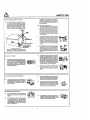
PROTECTION AND LOCATION OF YOUR SET
16-I. If an outside antenna is connected to the televi-
sion set, be sure the antenna system isgrounded
so as to provide some protection against voltage
surges and built up static charges, Section 810 of
the National Electrical Code, NFPA No. 70-1975,
provides inforrr_t_ with respect to proper
grounding of the mast and supporting structure,
ANTENNA
ELEC'n_C
(NEC_ECTK_N_HO2t)
. _ £LECTROIISYS1EM
(NECAnT_'_ _q'r _
EXAMPLE OF ANTENNA GROUNDING AS PER
NATIONAL ELECTRICAL CODE INSTRUCTIONS
16-2.
17.
18.
SAFETY TIPS
grounding of the lead-in wire to an antenna dis-
charge unit, size of grounding conductors, loca-
tion of antenna discharge unit, connection to
grounding electrode, and requirements for the
grounding electrode.
Note to CATV system installer:.
(Only for the television set with CATV reception)
This reminder is provided to call the CAW sys-
tem installer's attention to Article 820-40 of the
NEC that provides guidelines for proper ground-
ing and, in particular, specifies that the cable
ground shall be connected to the grounding sys-
tem of the building, as close to the point of cable
entry as practical.
An outside antenna system should not be located
in the vicinity of overhead power lines or other
electrical lights or power circuits, or where it can
fall into such power lines or circuits. When
installing an outside antenna system, extreme
care should be taken to keep from touching such
power lines or circuits as contact with them might
be fatal.
For added protection for this television set dudng
a lightning storm, or when it is left unattended and
unused for long periods of time, unplug it from the
wall outlet and disconnect the antenna. This will
prevent damage due to lightning and power-line
surges.
OPERATION OF YOUR SET
19. This television set should be operated only from
the type of power souroe indicated on the marking
label If you are not sure of the type of power
supply atyour home, consult your televisiort dealer
or local power company. For television sets
designed to operate from battery power, refer to
the operating instructions.
20.
21.
If the television set does not operate normally by
following the operating instructions, unplug this
television set frornthe wall outlet and referservic-
ing to qualified service personnel. Adjust only
those controls that are covered in the operating
instructions as improper adjustment of other con-
trois may result in damage and will often require
extensive work by a qualified technician to re-
store the television set to normal operation.
When going on a holiday: If your television sat is
to remain unused for • period ot time, turn the
television sat "off' and unplug it from the wall
outlet.
IF THE SET DOES NOT OPERATE PROPERLY
22. If you are unable to restore normal operation by
following the detailed procedure in your operat-
ing instructions, do not attempt any further ad-
_ justmenl. Unplug the set and call your dealer or
i service technician.
23.
24.
Whenever the television set is damaged or fails,
or a distinct change in performence indicates a
need for service, unplug the set and have it
checked by a professional septice technician.
It isnormal for some "iV sets to make occasional
snapping or popping sounds, particularly when
being turned on or off. If the snapping or popping
is continuous or frequent, unplug the set and
consult your dealer or service technician.
FOR SERVICING AND MODIFICATION
25. Do not use attachments not recommended by the
tekwision set manufacturer as they may cause
hazards.
26.
When roplecement parts are required, be sure
the service technician has used replacement
parts specified by the manufacturer that have the
same choracteristice as the original part. Unau-
thorized substitutions may result in fire, electric
shock, or other hazards.
27.
Upon completion of any service or repairs to the
television sat, ask the service technician to per-
form routine safety checks to determine that the
television is in safe operating condition.
4

PICTURE CAUTIONS
WARNING
Continuous on-screen displays such as
video games, stock market quotations,
computer generated graphics, and other
fixed (non-moving) patterns can cause per-
manent damage to projection television
receivers. Such "PATTERN BURNS" con-
stitute misuse and are NOT COVERED by
your Hitachi Factory Warranty.
When using the Picture-in-Picture function, the sub-picture should not be left permanently
in one corner of the screen or a "pattern burn" may develop over a long period of time.
This projection television receiver was intended mainly for the private viewing of programs
broadcast by TV stations and cable companies and programs from other video sources.
Public viewing may require prior authorization from the broadcaster or owner of the video
program.
5

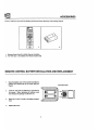
ACCESSORIES
Check to make sure you have the following accessories before disposing of the packing material.
r
_DOED
DD_D
_J LJ MII
rv| ,, rwl
O_Q
00_
m
m
.
.
1. Remote Control Unit CLU-415UI (Part No. HL00224)
2. Two "hA" size, 1.5V battedes (For Remote Control Unit)
REMOTE CONTROL BATTERY INSTALLATION AND REPLACEMENT
1.
2.
3.
Openthebatterycoverofthe remotetransmitterby
pushingthe notched part of the cover with your
fingers.
Inserttwo new "AA"size batteries or equivalent for
the remote. When replacing old batteries, push
them towards the spdngs and liftthem out.
Match the (+) and (-) marks in the battery compart-
ment.
BOTTOM VIEW
4. Replace the cover.

HOW TO SET UP YOUR NEW HITACHI PROJECTION TV
ANTENNA
Unless your TV isconnected to a cable TV system or to a centralized antenna system, a good outdoor color "IV antenna
is recommended for the best performance. However, if you are located in an exceptionally good signal area that is free
from interference and multiple image ghosts, an indoor antenna may be sufficient.
LOCATION
Select an area where sunlight or bright indoor illumination will notfall directly on the picture screen. Also, be sure that
the location selected allows a free flow of air to and from the perforated back cover of the set.
To avoid cabinet warping, cabinet color changes, and increased chance of set failure, do not place the TV where
temperatures can become excessively hot. For example, in direct sunlight or near a heating appliance, etc.
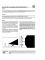
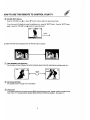
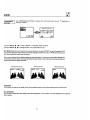
VIEWING
The major benefit ofthe HITACHI Projection Television is
itslarge viewing screen. To see this screen at itsbest,test
various locations in the room to find the best spot for
viewing. The drawings give several suggestions.
The best pictureisseen by sittingdirectly in front ofthe "IV
and about 10 to 18 feet from the screen. Picture bright-
ness decre,_ses as the viewer moves to the left or rightof
the receiver.
During daylighthours, reflectionsfrom outsidelight may
appear onthe screen. If so, drapesor screenscan be
usedto reducethe reflectionortheTV canbe locatedin
a differentsectionofthe room.
If the TV's audio output will be connected to a Hi-Fi
system's external speakers, the best audio performance
will be obtained by placing the speakers equidistant from
each side ofthe receiver cabinet and as close as possible
to the height ofthe picturescreen center. For best stereo
separation, place the external speakers at least 4 feet
from the side of the TV. Place the surround speakers to
the side or behind the viewing area. Differences in room
sizes and acoustical environments will require some ex-
perimentation with speaker placement for best perfor-
mance.
4' MINIMUM
4' MINIMUM
I _AUTION:
I
The magnetic field of extemal speakers may cause the TV pictureto distort ifthe speakers are I
placed too close to the television. Move the speakers away from the TV untilthere is nopicture
Idistortion.

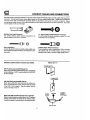
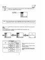
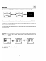
HOOKUP CABLES AND CONNECTORS
Mostvideo/audioconnectionsbetween componentscanbemadewithshieldedvideoand audiocablesthathavephono
connectors.Forbestperformance,videocablesshoulduse75-ohmcoaxialshieldedwire. Cablescanbepurchased
from moststoresthat sell audio/videoproducts.Beloware illustrationsand namesof commonconnectors. Before
purchasinganycables,besureoftheoutputandinputconnectortypesrequiredbythevariouscomponents.Alsomake
surethe cablesare thecorrectlength.
300-OhmTwin Lead Connector
This outdoorantenna cable must be connectedto an
antennaadaptor(300-Ohmto75-Ohm).
"F" Type 75-Ohm Coaxial Antenna Connector
For connecting RF signals (antenna or cable TV) to the
antenna jack on the television.
Phono Connector
Usedon allstandardvideoand audiocableswhichcon-
necttoinputsandoutputslocatedontheTelevision'srear
jackpanels.
S-Video (Super Video) Connector
Thisconnectorisusedoncamcorders,VCR's,andlaser
disc playerswith an S-Video feature in place of the
standardvideocabletoproducea high-qualitypicture.
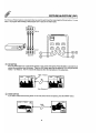
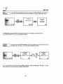
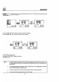
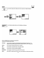
ANTENNA CONNECTIONS TO REAR JACK PANEL
VHF (75-Ohm) antenna/CAW(cable TV)
When using a 75-Ohm coaxial cable system, connect the
outdoor antenna or CATV coaxial cable to the VHF/UHF
75 Ohm terminal.
VHF (300-Ohm) antenna/UHF antenna
When usinga 300-Ohm twin lead from an outdooran-
tenna,connecttheVHF orUHF antennaleadstoscrews
ofthe VHF or UHF adaptor. Plugthe adaptorintothe
antennaterminalonthe "IV.
REAR OF TV
To outdoorantenna
or CATV cable
To outdoorVHF
or UHF antenna
t
When both VHF and UHF antennae are connected
Attach anoptional antenna cable mixer to the TV antenna
terminal, and connect the cables to the antenna mixer.
Consultyour dealer or service store forthe antenna mixer.
To outdoor
To UHF VHFIUHF antenna or
Antenna _ CATV system
-
Antenna mixer

FRONT PANEL CONTROLS
@
®
®
®
®
®
MENUBUTrON
Thisbutton allowsyouto entertheMENUmodewithoutusingtheremote.ThismakesitpossibletosetTVfeatures
toyourpreference,withoutusingtheremote.
AVX (AudioNideo) selector/ENTER button
Pressthisbuttontoselectthecurrentantennasource,VIDEO: 1 orVIDEO: 2. Yourselectionisshowninthetop
rightcornerofthescreen. Thisbuttonalsoservesasthe ENTER buttonwhenin MENU mode.
VOLUME level
Pressthesebuttonsforyourdesiredsoundlevel.ThevolumelevelwillbedisplayedontheTVscreen. Thesebuttons
alsoserveas thecursorleftandrightbuttonswheninMENU mode.
CHANNEL selector
PressthesebuttonsuntilthedesiredchannelappearsinthetoprightcorneroftheTVscreen. Thesebuttonsalso
serveasthe cursordownandup buttonswhenin MENU mode.
POWER button
PressthisbuttontoturntheTV onor off.
POWER light
Youwillsee a red lightwhenthe "IVisturnedon.
NOTE: YourHITACHI TV willappearto beturned"off"ifthere isnovideoinputwhenVIDEO: 1 orVIDEO: 2 is I
selected.Checkthe PowerLighttomakesuretheTV isoffwhennotin use.
I
@ AI (Artificial Intelligence) sensor
This"ArtificialIntelligence"sensorwillmakeautomaticpictureadjustmentsdependingontheamountoflightinthe
roomtogivethebestpicture. (See page34.)
® REMOTECONTROL sensor
PointyourRemoteatthis areawhenselectingchannels,adjustingvolume,etc.

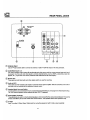
REAR PANEL JACKS
REAR SPEAKER
812 ONLY
SP, MATRIX
"_SURROUND
-.._×T.
VHF/UHF
o
o
,S-VIDE
(f,€_
k_
VIDE(
€_
INPL
VIDEO
(MO_LOl
0
INPU"
J
®
®
®
®
Antenna Input
Usean "F*typecoaxialcabletoconnectan antennaorcableTV (CATV)outputtothisrear paneljack.
Audio/Video Inputs 1, 2
The "AVX" (Auxiliary video) button will step through each video source and the current antenna input each time it
is pressed. Use the audio and video inputs to connect external devices, such as VCR's, camcorders, laser disc
players, etc. (If you have mono sound, insert the audio cable into the left channel jack.)
Monitor Out
These jacksprovidefixedaudioand videosignalswhichareusedforrecording,
Audio to Hi-Fi
These jacks provide variable audio outputto a separate stereo system amplifier. With this connection, the audio to
the stereo can be controlled by the television's remote control.
Speaker Matrix Surround Switch
Usethis switchto choose between the surroundand external speaker features. See page 13 forAudioSystem setup.
The TV's Internal Speakers will be switched off when "EXT. _ isselected.
Rear Speaker Terminals
These terminals are used to connect external speakers, whichare usedforthe surroundsound feature. The volume
level iscontrolled by the remote control main volume buttons. Use speakers with 8 Ohm impedance only.
O S-Video
Input 1 provides S-Video (Super Video) jacks for connecting equipment with S-Video output capability.
10

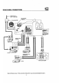
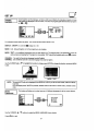
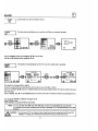
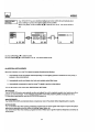
REAR PANEL CONNECTIONS
. Outsideantenna or
_=-"_cable TV coaxialcable
See connections
on page 12.
,_---_2-way signalsplitter /
/
SurroundSpeakers C_CT O_v. Oh.,_=_S
oo NOT _T Clmc_'f
A _HORT CIRCUIT MAY 0,NV,AGE
YOUA "IV
(=u=h_ i= NOT aov_d by
DO NOT _ Mb'T/qL8T.kPLE&
NALS, OR OTHER CONOIJCTIh_
MATID_ TO 8[-CU_E YOUR
6PFJ_ R WI=_G,
Optional,seetips
I.r-n
l t,l
Laserdiscplaye O O
camcorder, etc. 0 0 _':& O0 0 0
0 11111111111010
Laserdiscplayer,VCR,
Cable TV box
---_-_ _ oV__t
INPUT I
I v L R I I_"_
LO_001_F---_
1'-_ IF-"_
If _ C:_,_ VCR#2 Stereo SystemAmplif.r
Typicalfull feature setup. Followconnectionsthatpertaintoyourpersonalentertainmentsystem.
11

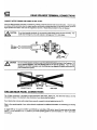
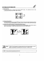
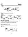
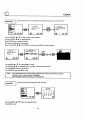
REAR SPEAKER TERMINAL CONNECTIONS
CONNECT AFTER TURNING THE POWER TO THE TV OFF
Press the Right Speaker red button and insert the positive(+) lead wire intothe hole next to the button. Once the wire
isin place, pull the red button back to original position and the wire is locked into place. In the same manner, press the
Right Speaker black button and insert the negative(-) lead wire. Repeat this procedure for the Left Speaker.
CAUTION:
Do notshort speaker terminals, (do notconnect a wire directly across any two terminals). This
could cause damage to your audio outputs or damage your TV in other ways.
I
TO
EXTERNAL <_
SPEAKER
R
®
!,_CAUTION:
Do notconnectspeakerssimultaneouslyto,he REARSPEAKERterminalof theProjectionTV
and an externalamplifier.Thiscoulddamage boththe TV andthe speakers. Your TV was
designedtouse8 Ohm speakersonly.Anyothertypemay degradethe audioperformanceof
yourentertainmentsystem.
PROJECTIONTV SPEAKER AMPLIFIER
TIPS ON REAR PANEL CONNECTIONS
The S-Videoconnectionis providedfor highperformancelaser discs.VCR's, etc., that havethis feature.Use this
connectioninplaceofthe standardvideoconnectionifyourdevicehasthisfeature.
Ifyourdevicehasonlyone audiooutput(monosound),connectittotheleftaudiojackontheTV.
Refertothe operatingguideofyour otherelectronicequipmentfor additionalinformationon connectingyourhookup
cables.
A single VCR can be used for VCR #1 and VCR #2, but note that a VCR cannot record its own video or line output
(INPUT: 1 in the example on p. 11). Refer to your VCR operating guide for more information on "line" input-output
connections.
t
12

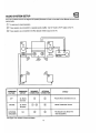
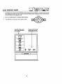
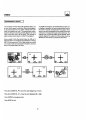
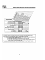
AUDIO SYSTEM SETUP (-I_1
Match the numbers below to the diagram for speaker placement and refer to the table for the different surround sound
requirements.
(_The television's internal speakers.
(_ These speakers are connected to a separate audio amplifier. Use the "Audio to Hi-Fi" output on the "IV.
(_ These speakers are connected tothe Rear Speaker 8 Ohm output on the TV.
@ @
c
J
SURROUND
FEATURE
OFF
MATRIX
SURROUND
SWITCH*
Sp. Matrix
Surround
Sp. Matrix
Surround
REQUIRED
CONNECTION
Q
EXTERNAL E_.
SPEAKERS
*SeepagelOforlocationofSurroundSw_ch.
®
OPTIONAL
CONNECTION
®
®
®
EFFECT
Receive Mono and Stereo Sound.
"Movie Theater-like" Sound.
This feature tums off the TV's
internal speakers.
13

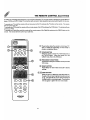
THE REMOTE CONTROL (CLU-415UI)
In additionto controlling all the functions onyour HITACHI ProjectionTV0the new remote is designed tooperate different
types ofVCR's and CATV (Cable TV) converters with one touch. Basic operation keys are grouped together inone area.
To operate your TV, point the remote at the remote sensor ofthe TV and press the TV button on the remote. The remote
will now control your TV.
To operate your VCR, pointthe remote at the remote sensor ofthe VCR and press the VCR button. The remote will now
control your VCR.
To operate your Cable Box, point the remote at the remote sensor ofthe Cable Box and press the CABLE button onthe
remote. The remote will now control your cable box.
PiP SWAP SHIFT FRZ
.0000
OQO
HITACHI
CLU-415UI
J
Q
®
®
®
Thesebuttonsallowtheremotetocontrolyour"IV,
VCR, or Cable Box dependingon whichmode is
chosen,as explainedabove.
"rv/vcR BUTTON
Whentheremoteisinthe TV orVCR mode,thisis
the TV/VCR button. When the remote is in the
CABLEmode,thisisthe A/Bbutton.
PRECODED VCR BUTTONS
These buttons always transmit the chosen precoded
VCR codes.
RESET BUTrON
PressRESETto returnvideoand audioto factory
settings.
(_),(_)LIGHT BUTTON
Whenyouare in a darkroom,pressthis button on
thesideoftheremoteto lightupthebuttonsshown
in_). The lightwillstayonfor about8 secondsif
thelightbuttonisnotpressedagain. Thesebuttons
willnotappearto lightifthe roomistoobright.
14

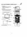
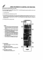
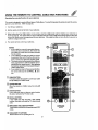
HOW TO USE THE REMOTE TO CONTROL YOUR TV
®
®
POWER Button
Press this button to turn the TV set on or off. If
MESSAGE-1 or MESSAGE-2 is set, it will be dis-
played when the TV is first turned on.
(See page 32.)
RECALL Button
When you want to check the channel being re-
ceived, or if it has a stereo (ST) or second audio
program (SAP), press the RECALL button.
You can also check the time, and if the ON TIME or
OFF TIME has been set. (See page 31.)
Audio Selected
CHANNEL n .p Channel
CAPTION_ _--IJ Indicator
'NEWS sTEVR EO 31_=,
STISA .-_, Audio
ON TIMER---_ .ON 7 00 AM II Broadcast
OFF TIMER I ooo*eooI I
If a video input is used:
VideoInput
,/
VIDEO:I
(s-m) _ Whenan S-Video
inputisconnected.
You can also use the RECALL button to quicklyclear many
of the other On-Screen Displays.
C)
RESET
CD
®
15

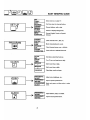
HOW TO USE THE REMOTE TO CONTROL YOUR TV
MENU, CURSOR Buttons
ENTER,
Allthe on-screendisplayfeaturescanbe setor adjustedbyusingthesebuttons.
The "MENU" buttonwillstartor exittheon-screen display.
The "CURSOR" buttons will highlight functions or adjust different features.
®
The "ENTER"buttonwillsetfeatures toyourpreference.
CHANNEL SELECTOR Buttons
"CHANNELSELECTOR" buttonsareusedto setthetime,for channelmemory,etc.
Entertwoorthreenumberstoselectchannels.Enter"0"firstforchannels1to9. Forchannel100 andhigher,press
the"1"button,waituntilanotherdashappearsnexttothechanneldisplayonyourTV, thenentertheremainingtwo
numbersusingthenumberbuttons.
Channel selection may also be performed by pressing channel up ( A ) or down (V).
NOTE: The TV may not receive some channels ifyou are not in the correct AIR/CABLE mode. See page 25,
I
AVX Button
The AVX (AuxiliaryVideo)buttonwillselectbetweenthe antennasignalandthevideoinputjackseachtimethe
buttonispressed. Ifthe Picture-in-Picture(PIP) ison,the AVXwill selectbetweenthevideoinputjacksonly.
(See page18.)
T
AVX
O
AVX
I
VIDEO:2
16

HOW TO USE THE REMOTE TO CONTROL YOUR TV
(_ VOLUME, MUTE Buttons
Press the "VOLUME" up (A) or down (V) button untilyou obtain the desired sound level.
To turn the sound off instantly to answer the telephone, etc., press the "MUTE" button. Press the "MUTE" button
again or press the "VOLUME" up (_k_) button to restore the sound.
MTV STEREO 28
VOLUME
llNNIHMlllllHllN_mnmon,m
Louder
>
CLOSED CAPTION will be displayed when the "MUTE" button is pressed.
O LAST CHANNEL (LST-CH) Button
Usethisbuttonto selectbetweenthe lasttwochannelsviewed.(Goodforwatchingtwosportingevents,etc.)
PRME STEREO 28
ST/SA
LST-CH
©
(_ PICTURE-IN-PICTURE
See separate section on page 18 for a description.
TEREO 39
(_ (SRD) button
Your Hitachi model does not access surround (SRD) using the remote control. Instead, a switch isprovided onthe
back ofyour TV to change between Speaker Matrix Surround and External speakers. (See page 13.)
17

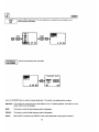
PICTURE-IN-PICTURE (PIP)
The Picture-in-Picture feature isconvenient when you want to watch morethan one program at the same time. You can
watch a TV program while viewing a VCR program (TV or tape) on the video inputs.
Back of TV
VIDEO IN
OUTPUT
1 o91
Back of VCR
®
(_) PIP BUTTON
Press the "PIP" button and a sub-picture appears in one comer ofthe screen. Press the button a second time to
remove the sub-picture from the screen. Press the AVX button when the sub-picture is on to change between
VIDEO: 1 or VIDEO: 2. The "IV channel will always be either the main picture or the sub-picture.
NEWS
Main Picture
STEREO=_ j
STISA
PIP
0
Sub-
(_ SWAP BUTTON
Ifyouwishtoswitchwhatisbeingshownon themainpicturetothesub-picture,pressthe "SWAP"button.
NEWS STEREO 31
ST/S/
SWAP
18

PICTURE-IN-PICTURE (PIP)
(_ SHIFT BUT[ON
To move the sub-picture to another comer, press the "SHIFT" button. The sub-picture moves one step
counterclockwise every time the "SHIFT" button is pressed.
_) FREEZE (FRZ) BUTTON
Ifyouwishtofreeze thesub-picture,pressthe"FRZ"button.Thisisconvenientwhentryingtowritedowntheaddress
for a mailordercompany,recordingstatisticsforasportingevent,etc. To returntomotion,pressthebuttonagain.
(_ FREEZE (FRZ) BUTTON WITHOUT A SUB-PICTURE (QUICK FREEZE)
Press this button without a sub-picture to freeze the picture you are currently viewing. Press this button again to
return to normal viewing. The SWAP button will not work with this QUICK FREEZE function.
i 1
STISA FRZ
,ACAUTION:
A pattern burn may develop ifthe sub-picture is left inthe same corner permanently. Ifthe PIP
feature is used frequently, occasionally shift the sub-picture to a different corner.
NOTE: Only soundfrom the mainpicturecanbe heard.
I
19

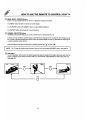
USING THE REMOTE TO CONTROL VCR FUNCTIONS
Operating the precoded function for your VCR
Thisremote isdesignedto operate differenttypes ofVCRs. You mustfirstprogram the remoteto matchthe remote system
in your VCR. (Refer to page 22.)
1. Turn ON yourVCR.
2. Aim the remote control at the front of your VCR.
3,
While holding down the VCR button onthe remote, enter the 2 digitpreset code that matches your VCR as shown on
page 22. The remote will turn off your VCR when the correct 2 digit preset code is entered. When this occurs,
the remote control is programmed for your VCR. If the VCR does not turn off after 5 seconds, try a different 2
digit preset code.
4. The remote will now control your VCR.
NOTES:
1. Ify.ourVCR cannot be operated after performing
the above procedures, this means that your
VCR's codes have not been precoded into the
remote.
2. In the unlikely event that your VCR cannot be
operated after performing the above procedures,
consult your VCR operating guide.
3. The remote control will remember the codes you
have programmed in until the batteries are re-
moved from the remote control. After replacing
the batteries repeat the entire programming pro-
cedure stated above.
4. If your VCR does not have a power function, the
remote will issue the CHANNEL A function.
(_VCR BUTTON
This allows the remote to controlyour VCR by
settingitto VCR mode.
Q PRECODED VCR BUr]-rONS
These buttons transmit the chosen precoded VCR
codes.
EXCLUSIVE TV BUTTONS
These buttonsareforoperatingtheTV.
20
Page is loading ...
Page is loading ...
Page is loading ...
Page is loading ...
Page is loading ...
Page is loading ...
Page is loading ...
Page is loading ...
Page is loading ...
Page is loading ...
Page is loading ...
Page is loading ...
Page is loading ...
Page is loading ...
Page is loading ...
Page is loading ...
Page is loading ...
Page is loading ...
Page is loading ...
Page is loading ...
Page is loading ...
Page is loading ...
Page is loading ...
Page is loading ...
-
 1
1
-
 2
2
-
 3
3
-
 4
4
-
 5
5
-
 6
6
-
 7
7
-
 8
8
-
 9
9
-
 10
10
-
 11
11
-
 12
12
-
 13
13
-
 14
14
-
 15
15
-
 16
16
-
 17
17
-
 18
18
-
 19
19
-
 20
20
-
 21
21
-
 22
22
-
 23
23
-
 24
24
-
 25
25
-
 26
26
-
 27
27
-
 28
28
-
 29
29
-
 30
30
-
 31
31
-
 32
32
-
 33
33
-
 34
34
-
 35
35
-
 36
36
-
 37
37
-
 38
38
-
 39
39
-
 40
40
-
 41
41
-
 42
42
-
 43
43
-
 44
44


Hitachi 50EX20B Operating instructions
- Category
- LCD TVs
- Type
- Operating instructions
- This manual is also suitable for
Ask a question and I''ll find the answer in the document
Finding information in a document is now easier with AI
Related papers
-
Hitachi 20CX20B User manual
-
-
-
-
-
-
-
-
-
Other documents
-
Zenith SY3272 Operating Manual & Warranty
-
Magnavox 6P5451C User manual
-
-
Haier HLT71 User manual
-
Apex GB43HD10 Owner's manual
-
Panasonic = Operating Instructions Manual
-
Memorex MPT -3460 User manual
-
ProScan EP5585 User manual
-
Simpli Home AXCPF-24 Operating instructions
-