Jacobsen 69177 Installation guide
- Category
- Lawnmowers
- Type
- Installation guide

When Performance Matters.
™
R311T
™
Rotary Mower with folding ROPS
69177 – Kubota
®
V2403-M-T
WARNING
WARNING: If incorrectly used this machine can cause severe
injury. Those who use and maintain this machine should be
trained in its proper use, warned of its dangers and should
read the entire manual before attempting to set up, operate,
adjust or service the machine.
4289796-GB-Rev B
Dealer Manual
GB
United
Kingdom

2
CONTENTS
This manual contains safety and operating instructions
for your new Jacobsen mower. This manual should be
stored with the equipment for reference during operation.
Before you operate your mower, you and each operator
you employ should read the manual carefully in its
entirety. By following the safety, operating, and
maintenance instructions, you will prolong the life of your
equipment and maintain its maximum efficiency.
If additional information is needed, contact your
Jacobsen Dealer.
The serial plate is located on the right rear frame rail.
Jacobsen recommends you record these numbers below
for easy reference.
11524 WILMAR BLVD,
CHARLOTTE, NC 28273
®
kg kW
1-800-848-1636 (US)
PRODUCT OF U.S.A.
A Textron Company
FOREWORD
CONTENTS
CONTENTS
1SAFETY
1.1 Important Safety Notes ........................................ 6
2 CONTROLS
2.1 Icons .................................................................... 7
2.2 Control Descriptions ............................................ 9
2.3 Control Panel Levers ......................................... 10
2.4 Control Panel Switches ...................................... 11
2.5 Gauges and Circuit Breakers ............................. 11
2.6 Warning Lights ................................................... 12
3SET UP
3.1 Initial Inspection ................................................. 14
3.1 Initial Assembly .................................................. 14
3.2 Operating Checks .............................................. 15
3.2 Interlock System ................................................ 15
4 ADJUSTMENTS
4.1 General.............................................................. 16
4.2 Ball Joints .......................................................... 16
4.3 Engine Alternator Belt ........................................ 16
4.4 Mow Speed ........................................................ 17
4.5 Weight Transfer ................................................. 17
4.6 Hydro Neutral .................................................... 18
4.7 Reverse Sensing Switch .................................... 18
4.8 Steering Toe In .................................................. 19
4.9 Turning Radius .................................................. 19
4.10 Steering Stop Bolts ............................................ 19
4.11 Cutting Height .................................................... 20
4.12 Leveling Front Mower ........................................ 21
4.13 Servicing Front Deck ......................................... 21
4.14 Torque Specification .......................................... 22
4.15 Specific Torque .................................................. 22
5 PROBLEM SOLVING
5.1 General.............................................................. 23
6NOTES
© 2013 Jacobsen, A Textron Company/Textron Innovations Inc.
“All rights reserved, including the right to reproduce this material
or portions thereof in any form.”
Proposition 65 Warning
This product contains or emits
chemicals known to the State of
California to cause cancer and birth
defects or other reproductive harm.
Litho In U.S.A. 9-2014

SAFETY 1
3
1 SAFETY
1.1 HOW TO OPERATE SAFELY ______________________________________________________
1.1.1 SAFE OPERATION
a Read the Operator’s Manual and other training
material. If the operator or technician can not read
this manual, the owner is responsible to describe
this material to the operators and technicians.
Manuals in additional languages may be available
on the Jacobsen or RansomesJacobsen website.
a Read all of the instructions for this mower carefully.
Know the controls and the correct operation of the
equipment.
b Children or persons who do not understand these
instructions must not use the mower. The local
regulations can limit the age of the operator.
c Never use a mower near persons, including children
or animals.
d Remember that the operator or owner is responsible
for accidents or hazards that occur to other persons
or their property.
e Never carry passengers.
f Never allow persons to operate or service the
mower or its attachments without correct
instructions.
g Do not operate equipment while tired, sick or after
you use alcohol or drugs.
1.1.2 PREPARATION
a When you operate the mower, wear correct clothing,
slip resistant work shoes or boots, work gloves, hard
hat, safety glasses and hearing protection. Long
hair, loose clothing or jewelry can be caught in
moving parts.
b Do not operate the equipment with the Interlock
System disconnected or the system does not
operate correctly. Do not disconnect or prevent the
operation of any switch.
c Never operate equipment that is not in correct order
or without decals, guards, shields, deflectors or
other protective devices fastened.
d Inspect the mower before you operate the mower.
Check the tire pressure, engine oil level, the radiator
coolant level and the air cleaner indicator. Fuel is
flammable. Use caution when you add the fuel to the
mower.
e Operate the mower in daylight or in good artificial
light. Use caution when you operate the mower
during bad weather. Never operate the mower with
lightning in the area.
f Inspect the area to select the accessories and
attachments that are needed to correctly and safely
do the job. Only use parts, accessories and
attachments approved by Jacobsen.
g Be careful of holes in the terrain and other hazards
that are not visible.
h Inspect the area where the equipment is operated.
Remove all objects you can find before you operate.
Be careful of obstructions above the ground (low
tree limbs, electrical wires) and also underground
obstacles (sprinklers, pipes, tree roots). Enter a new
area carefully. Look for possible hazards.
i Inspect the cutting system before you start the
mower. Make sure the blades are free to rotate.
When you rotate one blade, other blades can rotate.
1.1.3 OPERATION
a Never operate the engine without enough ventilation
or in an enclosed area. The carbon monoxide in the
exhaust fumes can increase to dangerous levels.
b Never carry passengers. Keep other persons or
animals away from the mower.
c Disengage all drives and engage the parking brake
before you start the engine. Only start the engine
with the operator in the seat. Never start the engine
with persons near the mower.
d Keep your legs, arms and body inside the operator
compartment while the mower is in operation. Keep
your hands and feet away from the cutting units.
e Do not use on the slopes greater than the safe slope
limit for the equipment.
f To guard against over turning or loss of control:
WARNING
EQUIPMENT OPERATED INCORRECTLY OR WITHOUT TRAINING CAN BE DANGEROUS.
Know the location and correct operation of controls. Operators without experience must receive instruction from
another person that knows the correct operation of the equipment before you operate the mower.
Only use parts, accessories and attachments approved by Jacobsen.
!

1 SAFETY
4
– Operate the mower up and down on the face of
slopes (vertically), but not across the face
(horizontally).
– Do not start or stop suddenly on slopes.
– Decrease the speed when you operate on slopes
or when you must turn. Use caution when you
change direction. Turf condition can change the
mower stability.
– Use caution when you operate the mower near
drop-offs, ditches or embankments.
– Be careful of holes in the terrain and other hazards
that are not visible.
g When you drive in the reverse direction, look
behind you and down to make sure the path is
clear. Do not operate the cutting units when you
drive in the reverse direction.
h Use caution when you go near corners, trees or
other objects that can prevent a clear view.
i Equipment must meet the current regulations to be
driven on the public roads.
j Before you move across or operate on the paths or
roads, turn off the PTO switch, lift the mowers and
travel at decreased speed. Look for traffic.
k Stop the blades when the mower is on any surface
that is not grass.
l Do not release the cut grass in the direction of
persons or allow persons near the mower while in
operation.
m Do not operate the mower with damaged guards or
without safety devices in position.
n Do not change the engine governor setting or over-
speed the engine. Never change or tamper with
adjusters that are closed with a seal for the engine
speed control.
o Before you leave the operator compartment, for
any reason:
– Disengage all the drives and lower attachments to
the ground.
– Engage the parking brake.
– Stop the engine and remove the key.
p When you hit an object or mower starts to cause
the vibration that is not normal, inspect the mower
for damage and make repairs.
q Decrease the throttle setting before you stop the
engine.
r Do not use this equipment for uses that the mower
was not made for.
1.1.4 ROPS
a The ROPS is a safety device. Keep the ROPS in
the vertical and locked position. Always use the
seat belt when you operate the mower. Make sure
the seat belt can be released quickly in an
emergency.
b Only operate the mower with the ROPS in the
folded position on flat and level surfaces when
necessary. Do not operate the mower with the
ROPS in the folded position on slopes, near sharp
edges or near water. There is no roll over
protection with the ROPS in the folded position.
c Check for clearance before you drive below
objects. Do not contact tree branches, electrical
wires or other objects with the ROPS.
d Do not use the seat belt with the ROPS in the
folded position.
e Inspect the ROPS for damage. Keep the ROPS
hardware fastened.
f Do not weld, drill, change or bend the ROPS.
Replace a damaged ROPS. Do not try to correct a
damaged ROPS.
g Do not remove the ROPS from the mower.
h Jacobsen must approve any changes to the
ROPS.
1.1.5 SAFE HANDLING OF FUELS
a The fuel and the fuel vapors are flammable. Use
caution when you add the fuel to the mower. The
fuel vapors can cause an explosion.
b Never use the containers that are not approved to
keep or transfer fuel.
c Never keep the mower or fuel containers near an
open flame or any device that can cause the
ignition of fuel or fuel vapors.
d Never fill the fuel containers inside a vehicle or on
a truck or trailer with a plastic liner. Always put the
fuel container on the ground away from your
vehicle before you fill the container.
e Refuel the mower before you start the engine.
When the engine is in operation or while the engine
is hot, never remove the fuel cap or add fuel to the
mower.
f Refuel outdoors only and do not smoke when you
add fuel. Extinguish all types of ignition.

SAFETY 1
5
g The fuel nozzle must touch the rim of the fuel tank
when you add fuel to the mower. Do not use a
device to lock the fuel nozzle in the open position.
h Do not over fill the fuel tank. Leave at least 1 inch
(25 mm) below the filler neck.
i Always tighten the fuel tank cap and container cap
after you add fuel.
j If the fuel spills on your clothing, change your
clothing immediately.
1.1.6 MAINTENANCE AND STORAGE
a Before you clean, adjust or repair this equipment,
push PTO switch to the OFF position, lower the
cutting unit to the ground, engage the parking
brake, stop the engine and remove the key.
b Make sure the mower is parked on a solid and level
surface.
c Never work on a mower that is lifted only by the
jack. Always use the jack stands.
d Never allow persons to service the mower or its
attachments without correct instructions.
e When the mower is parked, put into storage or left
without an operator, lower the cutting device unless
a positive mechanical lock is used.
f When you put the mower on a trailer or put the
mower in storage, close the fuel valve. Do not keep
fuel near flames or drain the fuel inside a building.
g Disconnect the battery before you service the
mower. Always disconnect the negative battery
cable before the positive battery cable. Always
connect the positive battery cable before the
negative battery cable.
h Charge the battery in an area with good airflow.
The battery can release hydrogen gas that is
explosive. To prevent an explosion, keep any
device that can cause sparks or flames away from
the battery.
i Disconnect the battery charger from the power
supply before you connect or disconnect the
battery charger to the battery. Wear protective
clothing and use insulated tools when you service
the battery.
j Be careful and wear gloves when you check or
service the cutting unit blades. Replace any
damaged blades, do not try to correct a damaged
blade.
k Keep your hands and feet away from parts that
move. Do not adjust the mower with the engine in
operation, unless the adjustment needs the engine
in operation.
l Carefully release the pressure from components
with stored energy.
m To prevent injury from the hot, high pressure oil,
never use your hands to check for oil leaks. Use
the paper or cardboard to find leaks.
n The hydraulic fluid pressure can have enough
force to enter your skin. If hydraulic fluid has
entered your skin, a doctor must remove the
hydraulic fluid surgically within a few hours or
gangrene can occur.
o When you service the hydraulic system, make sure
the hydraulic fittings, tubes and hoses are
tightened to the correct torque. Make sure the
hydraulic system is in good condition before you
start the engine.
p Keep the mower and the engine clean.
q Allow the engine to become cool before storage
and always remove the ignition key.
r Keep all nuts, bolts and screws tight to make sure
the equipment is in safe condition.
s Replace worn or damaged parts for safety.
Replace damaged or worn decals. Only use parts,
accessories and attachments approved by
Jacobsen.
t To decrease the fire hazard, remove materials that
burn from the engine, muffler, battery tray and fuel
tank area.
u Disconnect the battery and controller connectors
before you weld on this mower.
1.1.7 WHEN YOU PUT THE MOWER ON A
TRAILER
a Be careful when you load or unload the mower on
a trailer. Trailer must be wider than the mower and
can carry the weight of the mower.
b Use a full-width ramp to load or unload the mower
on a trailer.
c Use straps, chains, cables or ropes to fasten the
mower to the trailer. Both front and rear straps
must be sent down and toward sides of trailer.
d Make sure that all latches are correctly fastened.

1 SAFETY
6
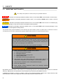
1.1 IMPORTANT SAFETY NOTES________________________________________________
This safety alert symbol is used to alert you to potential hazards.
DANGER - Indicates an imminently hazardous situation which, if not avoided, WILL result in death or serious injury.
WARNING - Indicates a potentially hazardous situation which, if not avoided, COULD result in death or serious
injury.
CAUTION - Indicates a potentially hazardous situation which, if not avoided, MAY result in minor or moderate injury
and property damage. It may also be used to alert against unsafe practices.
NOTICE - Indicates a potentially hazardous situation which, if not avoided, MAY result in property damage. It may
also be used to alert against unsafe practices.
For pictorial clarity, some illustrations in this manual may show shields, guards, or plates open or removed. Under no
circumstances should this equipment be operated without these devices securely fastened in place.
By following all instructions in this manual, you will prolong the life of your machine and maintain its maximum
efficiency. Adjustments and maintenance should always be performed by a qualified technician.
If additional information or service is needed, contact your Authorized Jacobsen Dealer who is kept informed of the
latest methods to service this equipment and can provide prompt and efficient service.
WARNING
The Interlock System on this mower prevents the mower from starting unless
the parking brake is Engaged, PTO switch is OFF, cruise control switch is
OFF, and traction pedal is in Neutral. The system will stop the engine if the
operator leaves the seat without engaging the parking brake, setting the PTO
switch OFF, and setting the PTO switch OFF.
NEVER operate mower unless the Interlock System is working.
!
WARNING
1. Before leaving the operator’s position for any reason:
a. Return traction pedal to Neutral.
b. Disengage all drives.
c. Lower all implements to the ground.
d. Engage parking brake.
e. Stop engine and remove the ignition key.
2. Keep hands, feet, and clothing away from moving parts. Wait for all
movement to stop before you clean, adjust, or service the machine.
3. Keep the area of operation clear of all bystanders and pets.
4. Never carry passengers.
5. Never operate mowing equipment without the discharge deflector
securely fastened in place.
!

CONTROLS 2
7
2 CONTROLS
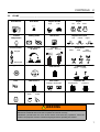
2.1 ICONS ___________________________________________________________________
WARNING
Never attempt to drive the mower unless you have read the Safety, Operation, &
Maintenance Manual and know how to operate all controls correctly.
Familiarize yourself with the icons shown above and what they represent. Learn the
location and purpose of all the controls and gauges before operating this mower.
Coolant
Temperature
D
Read Manual Engine Throttle
High Low
Hour Meter
Parking Brake Diesel Fuel Implement Position
Left Center Right
Cruise Control
Engine
Off Run Start
Drive Mode
2WD 4WD 4WD
Momentary
Engine Oil
Air Filter
Traction
Forward Reverse
PTO Switch
Engage Disengage
Filter Service
Lights
Work Road
Horn
Cutting Units
Raise Lower
Hydraulic Oil
Temperature Pressure
Glow Plug
Weight Transfer
to Decks
Increase Decrease
Engage
Disengage
Filter Service
!

2 CONTROLS
8
J-T XXXXXX-XXJ-T XXXXXX-XX
77
93
° C
170
200
° F
10 16
12 14
VOLTS
SOLID STATE
HOURS
00000
10 10 10 30 30 10
10 10 10 30 30 10
4192000
E
J
N
S
W
AA
F
F
K
P
T
X
AB
G
L
R
U
Y
A
B
C
D
H
M
V
Z
P
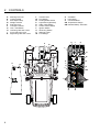
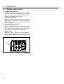
A Steering Tilt Lever
B Traction Pedal
C Mow Speed Stop
D Weight Transfer
E Seat Tilt Lever
F Transport Latches
G Horn / Test Switch
H Left Wing Lift/Lower Lever
J Front Lift/Lower Lever
K Right Wing Lift/Lower Lever
L Throttle Lever
M PTO Switch
N Parking Brake Switch
P Light Switch (Optional)
R 2WD / 4WD Switch
S Cruise Control Switch
T Ignition Switch
U Glow Plug Switch
V Warning Lights
W Fuel Gauge
X Volt Meter
Y Hour Meter
Z Circuit Breakers
AA Temperature Gauge
AB Remote Battery Terminals

CONTROLS 2
9
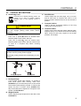
2.2 CONTROL DESCRIPTIONS__________________________________________________
A. Tilt Steering Lever
Pull lever up to release steering column. Tilt
column up or down to position desired.
Release lever to lock steering column in
place.
B. Traction Pedal
Press front of pedal (B
1
) down for forward travel.
Release pedal to slow mower and stop.
Press rear of pedal (B
2
) down for reverse travel.
Release pedal to slow mower and stop. Allow mower
to come to a complete stop before reversing
directions.
Figure 2A
C. Mow Speed Stop
Limits forward speed while mowing. To operate at
lower travel speed while mowing, rotate lever
(Position C
1
) so it contacts stop screw on floor board
when forward travel pedal is pressed. To travel at full
speed, set lever in position shown (Position C
3
).
Stop screw (C
2
) can be adjusted to set specific mow
speeds. See Section 8.4.
D. Weight Transfer
Used to adjust the ground pressure of the decks. See
Section 8.13.
E. Seat Tilt Lever
Used to adjust the rear seat angle. Lift up on lever
and tilt seat back as required until seat is in the
desired position. Release the lever to lock the seat in
position.
F. Transport Latches
Used to prevent accidental lowering of the wing
cutting units during transport.
G. Horn/Test Switch
Used to sound horn and test system warning lights.
Depress switch, horn should sound and all warning
lights, except for glow plug, engine oil and charge
pressure, should light.
CAUTION
Never adjust steering while mower is moving. Stop
unit and engage parking brake switch before
adjusting.
NOTICE
Engine will stop if traction pedal is depressed in either
direction with the parking brake engaged.
Disengage parking braked before attempting to drive
mower.
!
B
1
B
2
C
1
C
2
C
3
Transport Speed Mow Speed

2 CONTROLS
10
2.3 CONTROL PANEL LEVERS _________________________________________________
H. Left Wing Lift/Lower Lever
Raises and lowers left wing deck. Push lever forward
to lower left wing deck. Pull lever back to raise left
wing deck. Deck will start automatically when
lowered if PTO (M) switch is engaged.
J. Front Lift/Lower Lever
Raises and lowers front deck. Push lever forward to
lower front deck. Pull lever back to raise front deck.
Deck will start automatically when lowered if PTO (M)
switch is engaged.
K. Right Wing Lift/Lower Lever
Raises and lowers right wing deck. Push lever
forward to lower right wing deck. Pull lever back to
raise right wing deck. Deck will start automatically
when lowered if PTO (M) switch is engaged.
L. Throttle Lever
Regulates engine speed. Push lever forward to
increase speed or pull lever back to decrease speed.
Always operate mower at full throttle during normal
operation.
Figure 2B
L
H
J
K

CONTROLS 2
11
2.4 CONTROL PANEL SWITCHES _______________________________________________
M. PTO Switch
Lift up and push switch lever forward to engage
decks. Pull switch lever back to disengage.
Mower will automatically switch to 4WD with PTO
switch is engaged.
N. Parking Brake Switch
To engage parking brake, slide lock forward and
depress top of switch.
To disengage parking brake, depress rear of switch.
NOTE: Mower will not start with parking brake switch
in the Disengaged position.
P. Light Switch
Press front of switch for road lights. Press rear of
switch for work lights. Return switch to center
position to shut off lights.
R. 2WD / 4WD Switch
Used to switch mower between 2WD and 4WD
mode. Depress front of switch for 4WD in forward
direction only. Place switch in center position for
2WD. Depress rear of switch for momentary 4WD in
reverse. Do not engage or disengage 4WD while
mower is moving.
4WD is automatically put in 4WD when PTO switch is
engaged.
S. Cruise Control Switch
Depress traction pedal for desired speed, slide lock
forward and press front of switch to engage cruise
control. To disengage cruise control, press press rear
of cruise control switch, press rear of parking brake
switch (N), or turn ignition switch (T) to the OFF
position.
T. Ignition Switch
Used to start and stop the engine. The ignition switch
has three positions OFF, RUN, and START. To
prevent unauthorized use of this mower, remove
ignition key when not in use.
U. Glow Plug Switch
Used to energize the glow plugs before starting. Do
not hold switch for more than 7 seconds. Glow Plug
light will be on when switch is depressed.
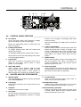
2.5 GAUGES AND CIRCUIT BREAKERS __________________________________________
V. Warning Lights
Alerts the operator to conditions requiring immediate
action. See Section 2.6.
W. Fuel Gauge
Displays fuel level in tank. Do not allow mower to run
out of fuel.
X. Voltmeter
Displays electrical system voltage.
Y. Hour Meter
Records engine operating hours. The hour meter can
be used to time maintenance intervals or mowing
operations.
Z. Circuit Breakers
Used to protect electrical system. Push down on
rubber boot to reset circuit breaker.
AA.Temperature Gauge
Displays engine coolant temperature. Do not operate
mower if temperature is above 230° F (110° C).
AB.Remote Battery Terminals
Used for connecting jumper cables with wing decks
in raised position. Keep red boot of positive remote
terminal in place when not in use.
J-T T XXXXXXXXXX-XX
77
93
° C
170
200
° F
10 16
12 14
VOLTS
SOLID STATE
HOURS
00000
10 10 10 30 30 10
10 10 10 30 30 10
L
T
X
H
M
R
U
Y
J
P
V
AA
Z
K
N
S
W
P

2 CONTROLS
12
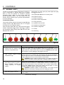
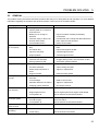
2.6 WARNING LIGHTS_________________________________________________________
The R311T-T4I mower monitors vital machine systems. It
uses a combination of warning lights and an audible
alarm to alert the operator of conditions requiring
immediate action. When an alert occurs follow the
general guidelines listed in the chart below, and any
specific actions outlined by the grounds superintendent
or service manager.
To test alarm system:
Turn ignition switch to RUN. The engine oil light (V
1
) and
charge pressure light (V
3
) should come on. All lights
should go out once engine is started.
Press horn/test switch (G). Horn will sound and Engine
Coolant Temperature (V
2
), Return Filter (V
4
), Hydraulic
Oil Temperature (V
5
), Charge Filter (V
6
), and Air Filter
(V
7
) lights will come on.
With engine off, press glow plug switch (U). Glow plug
light (V
8
) will come on.
Turn signal lights (V
9
) are not currently used.
This system monitors:
V1. Engine oil pressure
V2. Engine coolant temperature
V3. Charge pressure
V4. Hydraulic return oil filter
V5. Hydraulic oil temperature
V6. Hydraulic charge filter
V7. Air filter
V8. Glow Plug
Figure 2C
Alert Action
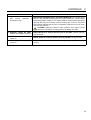
V1. Engine Oil Pressure - Alarm
sounds and oil pressure light
comes on. Oil pressure low.
Stop mower immediately, lower implements and shut off engine! Inspect
oil level in engine. If oil light remains on with oil at proper level, shut off
engine and tow or trailer mower back to service area. NEVER operate engine
with oil light on, severe damage to the engine can occur.
V2. Engine Coolant Temperature
Horn sounds. Engine coolant
temperature high.
Stop mower immediately, lower implements and shut off engine!
Remove debris such as leaves and grass clippings that may be restricting air
flow through rear screen on hood and area between radiator and oil cooler. If
engine continues to run hot, return mower to service area.
CAUTION: Engine coolant is under pressure. Turn engine off and allow
fluid to cool before checking fluid level or adding coolant to radiator.
V3. Charge Pressure Light stays on
after starting engine or comes on
during operation. Indicates low
charge pressure in traction
system.
Stop mower immediately, lower implements and shut off engine! Check
hydraulic oil level in main tank. Visually inspect mower for obvious signs of
leaks around connections, hoses and tubes. Tow or trailer mower back to
service area. Never operate mower with charge pressure light on, severe
damage to hydraulic system components can result.
CAUTION: Hydraulic system is under pressure. Turn engine off and
allow oil to cool before checking oil level or adding oil to tank.
V4. Hydraulic Return Oil Filter - Oil
filter warning light comes on.
Return mower to a service area as soon as possible. Change hydraulic
return oil filter.
Continued on next page
V
1
V
9
V
2
V
3
V
4
V
5
V
6
V
7
V
8
V
9

CONTROLS 2
13
V5. Hydraulic Oil Temperature
Horn sounds. Hydraulic oil
temperature high.
Stop mower, disengage drives and lower implements. Run engine at low
idle for a few minutes until light goes off. If light remains on, shut off engine
and allow hydraulic system to cool. Remove debris such as leaves and grass
clippings that may be restricting air flow through rear screen on hood and
area between radiator and oil cooler. If hydraulics continues to run hot, return
mower to service area.
CAUTION: Hydraulic system is under pressure. Turn engine off and
allow oil to cool before checking oil level or adding oil to tank.
V6. Hydraulic Charge Oil Filter -
Oil filter warning light comes on.
Return mower to a service area as soon as possible. Change hydraulic
charge oil filter.
V7. Air Filter - Air filter warning light
comes on.
Return mower to a service area as soon as possible. Change air filter.
V8. Glow Plug - Glow plug light
comes on.
Glow plug switch depressed. Do not energize glow plugs with engine
running.
Alert Action

3 SET UP
14
3 SET UP
3.1 INITIAL INSPECTION_______________________________________________________
The set-up and testing of the unit should always be
performed by a trained technician familiar with the
operation of this equipment.
Read each instruction completely and make sure you
understand it before proceeding with the assembly. Stay
alert for potential hazards and obey all safety
precautions.
The RIGHT and LEFT, FRONT and REAR of the
machine are referenced from the operator’s seat, facing
forward.
Accessories not included with this product must be
ordered separately. See instructions provided with
accessory for installation and parts.
3.1 INITIAL ASSEMBLY________________________________________________________
1. Check tires for proper inflation. Tires have been over
inflated for transport.
Mower:
Front - 16-20 psi (1.10-1.38 BAR)
Rear - 12-14 psi (0.83-0.96 BAR)
Deck - 20-25 psi (1.38-1.73 BAR)
2. Check battery connections
Make absolutely certain the ignition switch is “Off”
and the key has been removed before servicing the
battery.
Verify battery polarity before connecting or
disconnecting the battery cables.
When installing the battery, always assemble the
RED, positive (+) battery cable first, and the ground,
BLACK, negative (-) cable last.
Make sure battery is properly installed and secured
to the battery tray.
Tighten cables securely to battery terminals and
apply a light coat of silicone dielectric grease to
terminals and cable ends to prevent corrosion. Keep
vent caps and terminal covers in place.
3. Cut bands securing front deck and lower front deck
to the ground.
4. Check that front deck is leveled. [Section 4.12]
5. Set cutting height to customer specification.
[Section 4.11]
6. Check engine oil and add fuel to tank. Start engine.
7. Raise wing lift arms to their fully raised position.
8. Remove shipping bands, disengage wing transport
latches, and lower wing mowers to the ground. If
mowers will not lower, adjust weight transfer knob
as required. [Section 4.5]
CAUTION
Do not attempt to drive the mower unless you are
familiar with this type of equipment and know how to
operate all controls correctly.
!
WARNING
Make sure the mower is parked on a solid and level
surface. Never work on a mower that is supported
only by the jack. Always use jack stands.
CAUTION
Always use insulated tools, wear protective glasses or
goggles and protective clothing when working with
batteries. You must read and obey all battery
manufacturer’s instructions.
!
!
WARNING
Never operate the engine without proper ventilation;
exhaust fumes can be fatal when inhaled.
NOTICE
Allow engine to operate at low idle for at least one
minute before operating mower.
When starting engine at temperatures below 40° F (4°
C), operate the engine at low idle for five minutes to
prevent damage to engine or hydraulic system.
!

SET UP 3
15
3.2 OPERATING CHECKS ______________________________________________________
After the initial inspection test the mower for proper
operation. If mower is being fitted with an accessory you
may want to assemble these and check operation of the
mower with accessory attached.
1. Test the Interlock system.
[Section 3.2].
2. Start mower and check that switches, pedals, and
controls operate as described.
[Section 2.2]
3. Check that warning lights and alarm are working.
4. Operate traction pedal and check that mower
operates smoothly in both directions. Check that
mower stops when traction pedal is released.
5. Check that mower does not creep with engine
running and traction pedal in neutral.
[Section 4.6]
6. Check adjustment of traction pedal stop.
[Section 4.7]
7. Check that decks raise and lower correctly and that
power take-off switch operates. Make sure blades
turn off when decks are raised.
8. After operation, stop mower and inspect again for oil
or hydraulic leaks.
9. Check and if necessary adjust cutting height and
level front deck. [Sections and ]
3.2 INTERLOCK SYSTEM ______________________________________________________
1. The Interlock System prevents the engine from
starting unless the parking brake switch is ON,
traction pedal is in Neutral, cruise control switch is
OFF and the PTO switch is OFF. The system also
stops the engine if the operator leaves the seat with
the PTO switch ON, traction pedal out of neutral,
cruise control switch on, or parking brake switch
OFF.
2. Perform each of the following tests to insure the
Interlock System is functioning properly. Stop the
test and have the system inspected and repaired if
any of the tests fail as listed below:
l the engine does not start in test 1;
l the engine does start during tests 2, 3, 4, or 5;
l the engine continues to run during tests 6 or 7.
3. Refer to the chart below for each test and follow the
check (4) marks across the chart. Shut engine off
between each test.
Test 1: Represents normal starting procedure. The
operator is seated, parking brake switch is ON,
traction pedal is in Neutral, cruise control switch is
ON, and the PTO switch is OFF. The engine should
start.
Test 2: The engine must not start if the PTO switch is
ON.
Test 3: The engine must not start if the parking brake
switch is OFF.
Test 4: The engine must not start if the traction pedal
is not in Neutral.
Test 5: The engine must not start of the cruise control
switch is ON.
Test 6: Start the engine in the normal manner then
turn the PTO switch ON and lift your weight off the
seat. H
Test 7: Start the engine in the normal manner then
turn parking brake switch OFF and lift your weight off
the seat. H
H Lift your weight off seat. The engine will shut down.
WARNING
Never operate equipment with the Interlock
System disconnected or malfunctioning. Do not
disconnect or bypass any switch.
!
Test Operator
Seated
Parking
Brake Switch
Traction Pedal in
Neutral
PTO
Switch
Cruise Control
Switch
Engine
Starts
Yes No ON OFF Yes No ON OFF ON OFF Yes No
1 444 444
2 4444 4 4
3 444444
4 44 44 44
5 444 44 4
6 4H444 H
7 4H 44 4 H

4 ADJUSTMENTS
16
4 ADJUSTMENTS
4.1 GENERAL________________________________________________________________
1. Adjustments and maintenance should always be
performed by a qualified technician. If proper
adjustment cannot be made, contact an authorized
Jacobsen Dealer.
2. Replace, do not adjust, worn or damaged
components.
3. Long hair, jewelry, or loose fitting clothing may get
tangled in moving parts.
4. Do not change governor settings or overspeed the
engine.
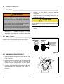
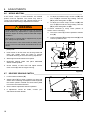
4.2 BALL JOINTS_____________________________________________________________
When adjusting ball joints, be sure cut-out in ball joint is
parallel to the mounting bracket, then secure in place.
Figure 4A
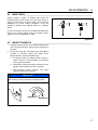
4.3 ENGINE ALTERNATOR BELT _______________________________________________
1. Inspect and adjust new alternator belt after the first
10 hours of operation. Check and adjust every 100
hours thereafter.
2. Adjust the alternator pulley so the belt deflects 9/32
to 11/32 in. (7 - 9 mm) with 22 lb. (10 kg) push at
midpoint between pulleys. Refer to your engine
manual.
3. To adjust, loosen alternator mounting bolts (A), and
adjust alternator until the proper belt tension is
achieved.
Figure 4B
WARNING
To prevent injury, lower implements to the ground,
disengage all drives, engage parking brake, stop
engine, and remove key from ignition switch before
making any adjustments or performing maintenance.
Make sure the mower is parked on a solid and level
surface. Never work on a mower that is supported
only by the jack. Always use jack stands.
If only the front or rear of the mower is raised, place
chocks in front of and behind the wheels that are not
raised.
!
CAUTION
Be careful to prevent entrapment of the hands and
fingers between moving and fixed components of the
machine.
!
INCORRECT CORRECT
Must be parallel
after assembly
within 1/4 in.
(6 mm) per foot.
A

ADJUSTMENTS 4
17
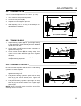
4.4 MOW SPEED______________________________________________________________
Cutting quality is better at speeds well below the
transport speed of the mower. An initial mow speed of
seven to eight mph is set at the factory and should be
satisfactory for most cutting conditions. Local turf
conditions however may respond better to a different
speed.
To set mow speed, loosen jam nut (R), and adjust stop
screw up to reduce speed, down to increase speed.
Tighten nut to hold adjustment in place.
Figure 4C
4.5 WEIGHT TRANSFER _______________________________________________________
1. Adjusting weight transfer knob affects lowering time
of the lift arms and also affects ground pressure at
each tire.
2. Loosen thin knob (J), and adjust large knob (K) to
increase or decrease cutting unit weight. Knob
adjusts all three mowers simultaneously.
a. Increasing cutting unit weight allows mowers to
follow contours of ground better and reduces
mower ground pressure.
b. Decreasing cutting unit weight increases mower
weight, which increases traction on slopes.
c. Once desired ground pressure has been
obtained, tighten thin knob (J).
Figure 4D
H
NOTICE
If cutting unit weight is set too low, wing cutting units
will not lower to the ground from transport position.
J
K
INCREASE
DECREASE

4 ADJUSTMENTS
18
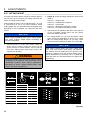
4.6 HYDRO NEUTRAL_________________________________________________________
If the mower “creeps” in either direction, the Neutral
position must be adjusted. The mower may tend to
“creep” if the hydraulic oil is cold. Operate mower for 15
minutes before determining if adjustment is needed.
1. Place a small amount of lubricating oil on all linkage
pivot points.
2. Hoist mower so all four tires are off the ground and
place jack stands under the frame to prevent
accidental lowering of the mower during adjustment.
3. Start engine and set throttle to full speed.
4. Disengage parking brake and place 2WD/4WD
Switch in 2WD position.
5. Check rotation of drive tires and adjust traction
return control (L) with the engine running.
a. To adjust for forward creep, loosen nut (M), and
turn nut (N) in until tires stop rotating. Hold nut
(N) in place and tighten nut (M).
b. To adjust for reverse creep, loosen nut (M), and
turn nut (N) out until tires stop rotating. Hold nut
(N) in place and tighten nut (M).
6. If mower continues to creep, check position of
traction return control (L).
a. The return control (L) must be parallel to traction
arm (O).
b. Loosen hardware (P) and adjust bracket (Q) until
control is parallel to arm.
Figure 4E
4.7 REVERSE SENSING SWITCH________________________________________________
1. Loosen switch hardware (R).
2. Adjust switch (S) so switch contacts are open with
switch roller contacting the adjustment block (T) and
the traction pedal in Neutral and close when pedal
is moved in the forward direction.
3. Secure switch adjustment and test operation.
4. If adjustment cannot be made, contact your
authorized Jacobsen Dealer.
Figure 4F
WARNING
Carbon monoxide in the exhaust fumes can be fatal
when inhaled. Any adjustments or repairs performed
while the engine is running must be made with ample
ventilation.
Never work on a mower that is supported only by the
jack. Always use jack stands.
If only the front or rear of the mower is raised, place
chocks in front of and behind the wheels that are not
raised.
!
M
N
O
P
Q
L
L
MUST BE PARALLEL
R
S
T

ADJUSTMENTS 4
19
4.8 STEERING TOE IN _________________________________________________________
“Toe in” should be adjusted from X + 1/16 in. (1.5 mm).
1. Turn wheels to straight ahead position.
2. Loosen tie rod jam nuts (U).
3. Adjust tie rod and retighten jam nuts.
4. After adjusting “Toe in” it may be necessary to re-
adjust steering stop bolts.
Figure 4G
4.9 TURNING RADIUS _________________________________________________________
1. Adjust steering cylinder (V) for equal angle steering
in both directions. Check that ball joints are threaded
equally into both ends.
2. Loosen both nuts (Y) and turn bolts completely in
against mounting block.
3. Loosen screw and nut (W) on locking clamp. Turn
cylinder rod to obtain desired length then retighten
hardware.
4. Fully extend and retract steering cylinder and
readjust steering stop bolts.
Figure 4H
4.10 STEERING STOP BOLTS____________________________________________________
Do not adjust the stop bolts until the “Toe in” and steering
cylinder have been adjusted.
1. Loosen both nuts (Y) and turn bolts completely in
against mounting block.
2. Fully retract steering cylinder. Adjust left side stop
bolt until it just touches steering arm. Tighten left
side nut (Y).
3. Fully extend steering cylinder. Adjust right side stop
bolt until it just touches steering arm. Tighten right
side nut (Y).
NOTE: Steering stop bolts must not limit the travel of the
steering cylinder rod stroke.
Figure 4I
X
X + 1/16 in. (1.5 mm)
U
U
V
W
W
Y
Y

4 ADJUSTMENTS
20
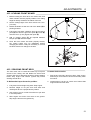
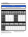
4.11 CUTTING HEIGHT _________________________________________________________
Level the front mower before setting the cutting height for
the first time. Do not remove the cutting units from the
mower to change cutting height.
Cutting height for decks can be adjusted from 1 to 5-1/2
in. (25-140 mm) in 1/2 in. (13 mm) increments. Actual
cutting height may vary somewhat from the heights given
depending on turf conditions, tire variances and other
factors.
1. Park the mower on a flat, level surface. Raise the
decks until the caster wheels are raised off the
ground enough so caster wheels can be removed
from deck. Place blocks under decks so they are
supported on all sides.
2. Figure 4J shows the height adjustment decal for the
casters.
Column 1 - Height of Cut
Column 2 - Arrangement of Spacers
Column 3 - Arm Position
Column 4 - Wing Mower Mounting Location
Column 5 - Front Mower Mounting Location
3. Adjust spacers in quantity listed. Store extra spacers
on top of spindle. Always leave one thin spacer
above and below caster arm.
4. For cutting heights 3 in. (76 mm) and below, caster
arms should be assembled to upper set of holes
(A). For cutting heights above 3 in. (76 mm), caster
arms should be assembled to lower set of holes (B).
Figure 4J
NOTICE
When cutting undulating areas, lower cutting heights
may cause scalping. Adjust height accordingly to
prevent turf damage.
WARNING
To prevent serious injury, lower deck until it is resting
completely on the supports. This will prevent it from
accidentally lowering while making adjustments.
Disengage all drives, engage parking brake, stop
engine, and remove ignition key.
!
NOTICE
After setting cutting height, fully lower cutting units
onto a flat, hard surface, stop engine, and measure
the distance from the blade tips to the ground. If the
distance is different from the desired cutting height,
make adjustments as necessary. Cut in a small test
area and make any final adjustments for desired turf
appearance.
1.0
2.0
3.0
4.0
5.0
1.0
3.0
5.0
1.5
2.5
3.5
4.5
2.5
4.5
5.5
1.0
1.5
2.0
2.5
3.0
3.5
4.0
4.5
5.0
5.5
A
B
"X"
"X"
0
1
2
3
4
0
1
2
3
4
A
A
A
A
A
B
B
B
B
B
Page is loading ...
Page is loading ...
Page is loading ...
Page is loading ...
Page is loading ...
Page is loading ...
-
 1
1
-
 2
2
-
 3
3
-
 4
4
-
 5
5
-
 6
6
-
 7
7
-
 8
8
-
 9
9
-
 10
10
-
 11
11
-
 12
12
-
 13
13
-
 14
14
-
 15
15
-
 16
16
-
 17
17
-
 18
18
-
 19
19
-
 20
20
-
 21
21
-
 22
22
-
 23
23
-
 24
24
-
 25
25
-
 26
26


Jacobsen 69177 Installation guide
- Category
- Lawnmowers
- Type
- Installation guide
Ask a question and I''ll find the answer in the document
Finding information in a document is now easier with AI
Related papers
-
 Jacobsen 10029628 Maintenance Manual
-
Ransomes 69167 Installation guide
-
Ransomes 68082 Installation guide
-
-
-
Ransomes 68131 Installation guide
-
-
 Jacobsen 10029628 Maintenance Manual
-
-


Other documents
-
-
-
-
-
-
-
-
-
-