Extron DTP T DWP 4K 232 D User manual

Category
Video switches
Type
User manual

This manual is also suitable for

1
IMPORTANT:
Go to www.extron.com for the
complete user guide
, installation
instructions, and specifications.
DTP T DWP 4K D Series • Setup Guide
This setup guide provides instructions for an experienced installer to set up and operate the Extron DTP T DWP 4K D series of
twisted pair (TP) wallplate extenders.
Installation
Step 1 — Disconnect Power
Disconnect all equipment power sources.
Step 2 — Prepare the Mounting Surface
ATTENTION:
Installation and service must be performed by
authorized personnel.
L’installation et l’entretien doivent être effectués par le
personnel autorisé uniquement.
The unit must be installed in accordance with the
National Electrical Code and with local electrical and
safety codes.
L’unité doit être installée conformément au National
Electric Code et aux normes électriques et de sécurité
locales.
NOTE: Use a UL-listed junction box with a depth of at least 3.0 inches (7.6 cm). Alternatively, the included mud ring (MR
200) can be used. For more information, see the full product user guide at www.extron.com.
a. Place the junction box against the installation surface and mark the opening guidelines.
TIP: Use a level to mark the opening.
b. Cut out the material from the marked area.
c. Secure the junction box to the wall stud with 10-penny nails, #8 screws, or #10 screws, leaving the front edge ush with the
surface.
d. Run all required cables (see steps 3, 4, and 5) and secure them with cable clamps.
TIP: In order to t the unit in the junction box, do not install boots on TP cables and RJ-45 connectors.
Extron
DTP T DWP 4K 332 D
Signal Output
Cable
Cable
Clamp
Decorator-Style Faceplate
Screws or
Nails
Wall opening is
flush with edge of box.
Wall Stud
AUTO SW
CONFIG
HDMI IN
AUDIO IN
HDBT
DTP
HDCP
1
AUDIO IN
DP IN
TLP 1000T
V
IPCP 505
IN1608
DTP HDMI 230 Rx
Projector
100-240V ~ -- A MAX
1
2
CONFIGURABLE
HDMI
HDMI
5
6
7
8
C
RS-232 IR
RS-232 IR
Tx Rx Tx RxG
Tx Rx Tx RxG
Tx Rx Tx RxG
HDMI
A
B
3
4
INPUTS
OUTPUTS
Tx Rx
RS-232
G
LAN
2x25W(8Ω)/2x50W(4Ω)
RESET
AUDIO INPUTS
OUTPUTS
REMOTE
LL1R R
L2
R
L
3
R
CLASS 2 WIRING
L4
R
L5R
+48V
+48V
12
LR
VARIABLE
IN1608 SA
2
MIC/LINE
L6
R
SIG LINK
DTP IN
SIG LINK
DTP IN
SIG LINK
DTP OUT
50/60 Hz
RS-232 IR
OVER DTP
OVER DTP
OVER DTP
AMPLIFIED OUTPUT
VOLUME
SCALING PRESENTATION SWITCHER
IN1608
INPUTS
1
HDCP
SIGNAL
OUTPUTS
ENTER
MENU
Extron
2 3 4 5 6 7 8 A B C
INPUTS
1 2 3 4 5 6 7 8
CONFIG
Extron
DTP T DWP 4K 232 D Tx
Transmitter
Ethernet
Network
LR
POWER
12V
0.7A MAX
AUDIO
SIG LINK
DTP IN
OUTPUTS
XTP DTP 24 Cable
230'
HDMI
12345678
100
LINK
ACT
COM
IR/S
TX
RX
TX
RX
RTS
CTS
R
5
1
6
2
7
3
8
4
RELAY
FLEX
I/O
5
1
6
2
3
1
4
2
eBUS
ACT LIMIT
OVER
SWITCHED
12VDC
3
1
4
OVER
2
LIMIT
IR
7
3
8
4
IPCP 505
AUDIO IN
DP IN
AUDIO IN
HDMI IN
Extron
2
DTP T DWP 4K D Series • Setup Guide (Continued)
Step 3 — Connect Inputs to the Extender
Front panel
A
Audio input connectors — Connect an unbalanced stereo audio
source to this 3.5 mm mini stereo jack.
B
HDMI input connector — Connect an HDMI cable between this port
and the output port of the digital video source.
C
DisplayPort input connector — Connect a DisplayPort cable
between this port and the output port of the video source.
D
Mini USB port — Connect a male USB mini-B cable to this port for
SIS configuration and firmware updates.
Rear panel
A
DC power input connector — Wire and plug the included external 12 VDC power supply into either this 2-pole connector or
the power input connector on the receiver (see the DTP T DWP 4K 232/332 D User Guide at
www.extron.com for wiring information).
B
Over TP connector — Connect an RS-232 device, IR device, or both to this 5-pole, 3.5 mm captive screw connector for
bidirectional pass-through device control. Wire the connector as shown in the diagram below. The Ground pin is shared by
both devices.
RS-232 — Connect an RS-232 device and congure it as follows: 9600 baud rate, 8 data bits,1 stop bit, no parity.
IR — Bidirectional TTL level (0 to 5 V) modulated infrared from 30 kHz to 60 kHz.
C
Remote connector — Connect an RS-232 device to this 3-pole, 3.5 mm captive screw connector for SIS configuration and
firmware updates. Wire the cable as shown in the diagram below.
D
Ground port — Use the included grounding strap to ground the unit to a junction box or other grounding point.
Ground
Transmit pin on connected unit
Receive pin on connected unit
Connected RS-232 and
IR Device Pins
Transmit pin for IR control
Receive pin for IR control
RxTx
RS-232 IR
RxTx
G
OVER TP
A
DC power input connector
B
Over TP connector
C
Remote connector
D
Ground port
E
DTP Out connector (page 3)
F
Reset button (page 3)
G
DTP/HDBaseT switch (page 3)
POWER
12V
1.1 A MAX
DTP T DWP 4K 232 D
RS-232 RS-232 SIG LINK
Tx Rx Tx Rx G Tx Rx G
IR
RESET
OVER TP REMOTE
OUT
F
A
B
C
D
DTP T DWP 4K D Rear Panel
E
HDBT
DTP
G
DTP T DWP 4K D Side Panel
AUDIO IN
AUTO SW
HDCP
1
2
CONFIG
HDMI IN
AUDIO IN
DP IN
Extron
A
B
C
A
D
DTP T DWP 4K D Front Panel
Tx Rx G
RS-232
Ground
Transmit pin on connected uni
t
Receive pin on connected unit
3
E
DTP Out connector — Connect one end of a twisted pair cable to this RJ-45 connector and the opposite end to a
compatible receiving device.
ATTENTION:
Do not connect this output to a telecommunications or computer data network.
Ne connectez pas ces appareils à des données informatiques ou à un réseau de télécommunications.
F
Reset button — Use an Extron Tweeker or small screwdriver to press and hold the recessed button while cycling power to
the extender to perform a factory reset.
G
DTP/HDBaseT switch — Set this 2-position, recessed switch to configure the output between HDBaseT and DTP modes.
When configured for HDBaseT, use an HDBaseT-compatible receiving device. When configured for DTP, use a DTP-
compatible receiving device.
NOTES:
When the switch is set to DTP mode, remote power is available and a single power supply connected to either
a extender or compatible receiver can power both units.
When the switch is set to HDBaseT mode, remote power is disabled and power supplies are required for both
extender and a receiving device. Analog audio is enabled, but incompatible with third-party HDBaseT devices.
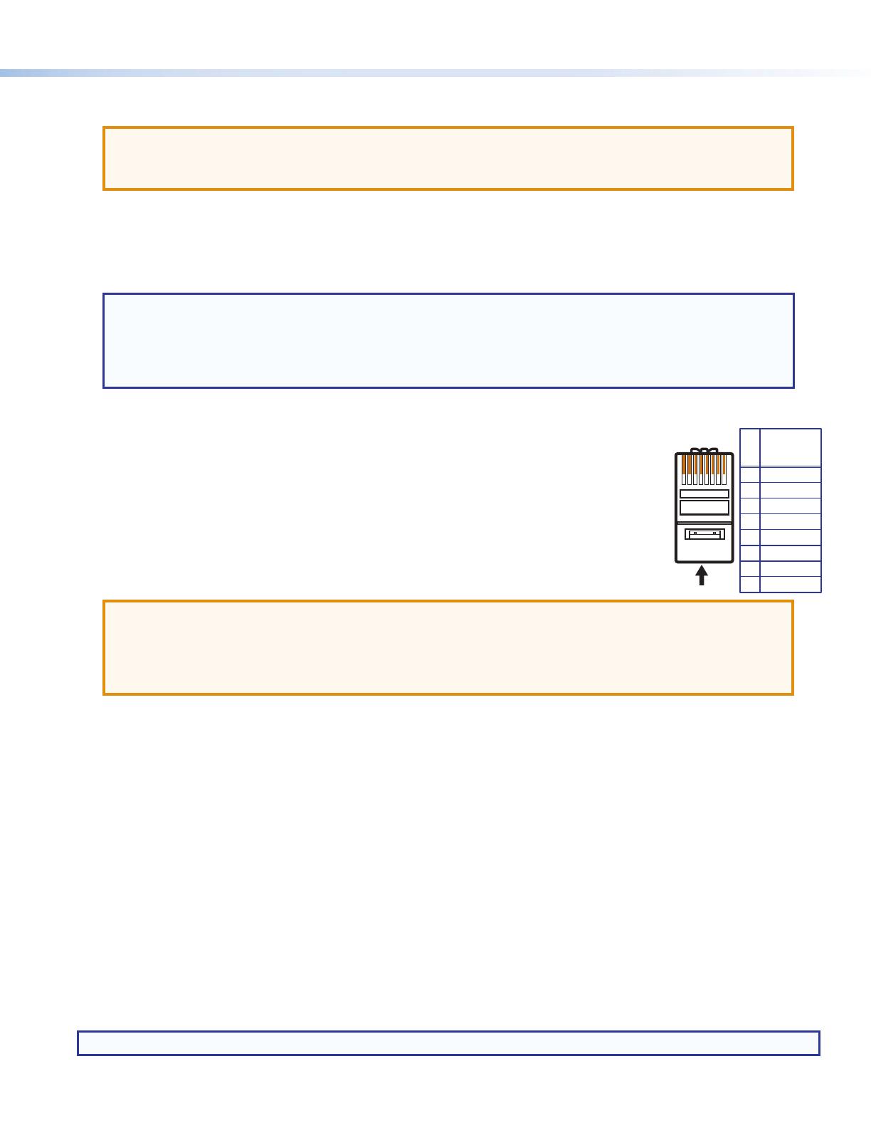
Step 4 — Run Cables Between Units
Connect the rear panel extender output to a rear panel receiving device input using twisted pair cable.
Wire the cable as shown in the diagram to the right.
For optimal performance, Extron highly recommends the following:
RJ-45 termination with shielded twisted pair cable must comply with TIA/EIA-T568B wiring
standard for all connections. For more information on TP cable wiring and termination, see the full
product user guides at www.extron.com.
Use shielded twisted pair cable, 24 AWG solid conductor or better, with a minimum cable
bandwidth of 400 MHz.
ATTENTION:
Do not use Extron UTP23SF-4 Enhanced Skew-Free AV UTP cable or STP201 cable to link the device with
DTP extenders or receivers.
N’utilisez pas le câble AV Skew-FreeUTP version améliorée UTP23SF d’Extron ou le câble STP201 pour relier
le appareil avec les émetteurs ou les récepteurs DTP.
Use shielded RJ-45 plugs to terminate the cable.
Limit the use of RJ-45 patches. Overall transmission distance capabilities vary depending on the number of patches used. If
possible, limit the number of patches to two total.
If RJ-45 patches must be used in the system, shielded patches are recommended.
Step 5 — Connect the Outputs from a Compatible Receiver
a. Connect an HDMI or DisplayPort cable (depending on your receiving device type) between the receiving device output port
and the input port of the display.
b. Connect a stereo audio device to the 3.5 mm mini stereo jack to receive the passed-through unbalanced audio.
c. Plug an RS-232 or modulated IR device into the RS-232/IR pass-through port.
Step 6 — Power the Units
The units can be powered one of two ways:
Locally with the included power supply. A compatible receiving device can be powered remotely through the DTP line.
Remotely via the DTP line by a locally powered DTP 230 or 330 compatible device.
NOTE: See notes in
G
above for remote power restrictions.
5
Pin
1
2
3
6
7
8
4
Wire color
White-green
Green
White-orange
White-blue
Orange
White-brown
Brown
Blue
TIA/EIA
T568-B
TP Wires
12345678
Pins:
4
68-2762-50 Rev. B
5 17
© 2015 Extron Electronics — All rights reserved. All trademarks mentioned are the property of their respective owners. www.extron.com
Step 7 — Final Installation
a. Make all connections, power the units, and test the system for satisfactory operation.
b. At the power outlet, unplug the power supply.
c. Mount the extender into the wall box, and attach the supplied decorator-style faceplate to the unit.
d. At the power outlet, reconnect the power supply. This powers up both units.
Operation
NOTE: Input switching can be performed via auto switching, RS-232, or IR through the rear panel connectors.
After all devices are powered up, the system is fully operational.
Extender LEDs
A
LEDs — These two-color front panel LEDs on the extenders light to indicate signal and power status as follows:
Amber — The unit is receiving power but there is no signal on the associated input.
Green — The unit is receiving power and a signal is present on the associated input.
B
Switch LED — Lights green when auto switch is active.
C
LEDs — Light green when an HDMI or DisplayPort input has been authenticated on the source device.
Audio Configuration
The DTP T DWP 4K D series can embed analog audio inputs onto the digital video output.
NOTE: If no HDMI or DisplayPort signal is present, analog audio transmitted over the DTP connection to the analog audio
output of the receiver.
When an input is selected, audio transport over HDMI or DisplayPort can be congured to operate in one of three modes. Each
input can be congured individually for any of the three modes.
Transport digital embedded audio (default) — The digital embedded audio content on the digital video input is transported.
Analog audio is still separate from the digital embedded audio on the HDMI or DisplayPort signal and transported
simultaneously over the DTP output, not embedded onto the digital output.
Embed analog audio input — The analog audio input is always embedded to the digital output, replacing whatever content
is already present on the digital embedded audio. Analog audio is also transported over the DTP output as a simultaneous
output.
Auto select between analog audio and digital embedded audio — When both analog audio and digital embedded audio
on HDMI or DisplayPort are present, digital embedded audio on the HDMI or DisplayPort signal takes priority. Analog audio is
transported simultaneously with the digital embedded audio content that is already present on the DTP output.
AUDIO IN
AUTO SW
HDCP
1
2
CONFIG
HDMI IN
AUDIO IN
DP IN
Extron
A
A
B
C
DTP T DWP 4K D Front Panel
1 / 1

Extron DTP T DWP 4K 232 D User manual

Category
Video switches
Type
User manual
This manual is also suitable for

Ask a question and I''ll find the answer in the document

Finding information in a document is now easier with AI

Ask the document