Cables
Camera
Product & Accessories Part Name Installation
Before installing your camera, read the following carefully.
1. The mounting surface must withold at least ve time the weight of the camera.
2. Do not let any cables get caught or the electric cver be damaged during installation.
Safety Information
This symbol indicates that dangerous voltage consisting a risk of electric shock is present within
this unit.
This exclamation point symbol is intended to alert the user to the presence of important
operating and maintenance (servicing) instructions in the literature accompanying the appliance.
To prevent damage which may result in fire or electric shock hazard, do not expose this
appliance to rain or moisture.
1. Be sure to use only the standard adapter that is specified in the specification sheet.
Using any other adapter could cause fire, electrical shock, or damage to the product.
2. Incorrectly connecting the power supply or replacing battery may cause explosion, fire,
electric shock, or damage to the product.
3. Do not connect multiple cameras to a single adapter. Exceeding the capacity may
cause abnormal heat generation or fire.
4. Securely plug the power cord into the power receptacle. Insecure connection may
cause fire.
5. When installing the camera, fasten it securely and firmly. A falling camera may cause
personal injury.
6. Do not place conductive objects (e.g. screw drivers, coins, metal things, etc.) or
containers filled with water on top of the camera. Doing so may cause personal injury
due to fire, electric shock, or falling objects.
TO REDUCE THE RISK OF ELECTRIC SHOCK, DO NOT REMOVE COVER (OR BACK) NO USER
SERVICEABLE PARTS INSIDE. REFER SERVICING TO QUALIFIED SERVICE PERSONNEL.
CAUTION
:
CAUTION
RISK OF ELECTRIC SHOCK.
DO NOT OPEN
WARNING
WARNING
7. Do not install the unit in humid, dusty, or sooty locations. Doing so may cause fire or
electric shock.
8. If any unusual smells or smoke come from the unit, stop using the product. In such case,
immediately disconnect the power source and contact the service center. Continued
use in such a condition may cause fire or electric shock.
9. If this product fails to operate normally, contact the nearest service center. Never
disassemble or modify this product in any way.
10. When cleaning, do not spray water directly onto parts of the product. Doing so may
cause fire or electric shock.
1. Do not drop objects on the product or apply strong shock to it. Keep away from a
location subject to excessive vibrationor magnetic interference.
2. Do not install in a location subject to high temperature low temperature or high
humidity. Doing so may cause fire or electric shock.
3. If you want to relocate the already installed product, be sure to turn o the power and
then move or reinstall it.
4. Remove the power plug from the outlet when then there is a lightning. Neglecting to
do so may cause fire or damage to the product.
5. Keep out of direct sunlight and heat radiation sources. It may cause fire.
6. Install it in a place with good ventilation.
7. Avoid aiming the camera directly towards extremely bright objects such as sun, as this
may damage the image sensor.
8. Apparatus shall not be exposed to dripping or splashing and no objects filled with
liquids, such as vases, shall be placed on the apparatus.
9. The Mains plug is used as a disconnect device and shall stay readily operable at any
time.
CAUTION
Important Safety Instructions
1. Read these instructions.
2. Keep these instructions.
3. Heed all warnings.
4. Follow all instructions.
5. Do not use this apparatus near water.
6. Clean only with dry cloth.
7. Do not block any ventilation openings. Install in accordance with the
manufacturer’s instructions.
8. Do not install near any heat sources such as radiators, heat registers, or other
apparatus (including ampliers) that produce heat.
9. Do not defeat the safety purpose of the polarized or grounding-type plug.
A polarized plug has two blades with one wider than the other. A grounding
type plug has two blades and a third grounding prong. The wide blade or the
third prong is provided for your safety. If the provided plug does not t into
your outlet, consult an electrician for replacement of the obsolete outlet.
10. Protect the power cord from being walked on or pinched particularly at plugs,
convenience receptacles, and the point where they exit from the apparatus.
11. Only use attachments/accessories specied by the manufacturer.
12. Use only with cart, stand, tripod, bracket, or table specied
by the manufacturer, or sold with the apparatus.
13. Unplug this apparatus when a cart is used. Use caution
when moving the cart/apparatus combination to avoid
injury from tip-over.
14. Refer all servicing to qualied service personnel. Servicing is required when the
apparatus has been damaged in any way, such as power supply cord or plug
is damaged, liquid has been spilled or objects have fallen into the apparatus,
the apparatus has been exposed to rain or moisture, does not operate
normally, or has been dropped.
WARNING
This equipment has been tested and found to comply with the limits for a Class A digital device, pursuant to part 15 of the FCC Rules.
These limits are designed to provide reasonable protection against harmful interference when the equipment is operated in a
commercial environment. This equipment generates, uses, and can radiate radio frequency energy and, if not installed and used in
accordance with the instruction manual, may cause harmful interference to radio communications. Operation of this equipment in a
residential area is likely to cause harmful interference in which case the userwill be required to correct the interferenece at his own
expense.
To disconnect power from the mains, pull out the mains cord plug. When install the product, ensure that the plug is easily
accessible.
Quick Start Guide
Ver. 1.0 / 2014.11
Before installing and using the camera, please read this manual carefully.
Be sure to keep it handy for future reference.
Please check if all the camera and accessories are included in the package.
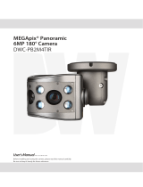
DWC-PB2M4TIR
MEGApix® PANO 2.1MP 180° Camera
Sunshield Sunshield ScrewsScrew & Plastic Anchor-4pcs 2nd BNC Output Cable
Manual CDQuick Start Guide Template Sheet T-Wrench
Ball Neck Bracket
Cables
Pan/Tilt stoper screw
Con Cap
Lens
Sunshield
SD Card Slot
Test Video OutputReset Button
1
2
3
4
5
Using the Mounting Template or the
camera itself, mark and drill the
mounting holes.
Pass cables through and connect the
cables respectively. See the section
‘Cabling’ for more information.
Secure the camera to the wall/ceiling
using the provided screws.
Before securing the camera to the mounting
surface, slightly loosen the Pan/Tilt stoper screw.
Using the secondary BNC output,
check the camera’s view and adjust as
needed during installation.
Attach the Sunsheild to the bottom case
by using Sunshield Screws.
Reset to the Factory Default
Press the reset button for 5 seconds to
return the camera’s settings to their
factory default.
Warning:
Pressing the ‘Reset’ button will result
in loss of all setting data. If needed,
make a note for further installation.
20150316
TEL: (866) 446-3595
www.Digital-Watchdog.com / [email protected]
Technical Support Hours: Monday-Friday 9:00AM to 8:00PM EST

1
Cabling
1
Power
4
Audio Input
2
Network
Connection
3
Audio Output
5
Alarm Output
6
Alarm Input
Power Connection
Please, check the voltage and current
capacity of rated power carefully.
3
4
Alarm Output
Connects to alarm lights, siren or
lamps and is activated according to
the Setup Menu settings.
Connect the relay output device’s
cables to the red and black lines of the
Alarm Cables.
Audio Output
Connect the ‘Audio Out’ cable of the
camera to a device such as a speaker.
Audio Input
Connect the ‘Audio In’ cable of the
camera to a device such as a
microphone.
2
Network Connection
Connect the crossover cable into the
RJ-45 port.
5
6
Rate
Power
Current
Consumption
DC 12V 6W (IR Off)
19W (IR On)
PoE
IEEE 802.3at
PoE+ /
High Power PoE
Alarm Input/Sensor
Connect the sensor/alarm input
device’s cables to the white and yellow
lines of the Alarm Cables.
Disposal of Old Appliance
1. When this crossed-out wheel bin symbol is attached to a product it means the
product is covered by the European Directive 2002/96/EC.
2. All electrical and electronic products should be disposed of separately form the
municipal waste stream in accordance to laws designated by the government or the
local authorities.
3. The correct disposal of your old appliance will help prevent potential negative
consequences for the environment and human health.
4. For more detailed information about disposal of your old appliance, please contact
your city oce, waste disposal service or the shop where you purchased the product.
Web Viewer Screen
3
4
9
Web viewer is optimized with Windows
XP or above and Internet Explorer browser.
Live video display. This area displays
live video stream from the camera.
Resolution. The resolution information
of the video currently in display.
SD Card Search. Searching or Playing
images stored in the SD Card.
Setup popup button. Click it to open
the camera’s setup page. This allows
you to setup the camera’s Video,
Network, Events, System etc.
Control tab button. Click the button to
extend the panel for full control of the
web-viewer’s function.
PTZ control button. Click the button to
extend the panel to control the camera’s
Pan, Zoom, Preset, Tours etc.
Full screen button. Click the button to
extend the display to full screen. Press
‘Esc’ or ‘Enter’ to return to normal mode.
Camera Setup button. Click the button
to open the Setup page to setup the
camera’s image settings such as lens,
white balance, auto exposure, BLC etc.
Event alert icon. If Alarm in and Motion
detection are detected, below icons will
appear.
1
2
<Alarm Input> <Motion Detection>
4
7
5
6
8
9
2 31
White : DIN+
Yellow : DIN-
Black : DOUT-
Red : DOUT+
If necessary you can change the
camera’s network type.
6
2
3
4
5
6
7
8
9
10
11
12
Select DHCP if the internet service is
dynamic IP. This will allow the camera to
receive its IP address from the DHCP server.
Select STATIC if the camera’s IP address is
received from a network
administrator. If the
camera is set to STATIC, manually enter the
camera’s IP address, subnet mask, Gateway
and DNS information.
If the camera is set to STATIC, please contact
your Network Administrator or internet
service provider for more information.
1
2
3
4
5
1. Run IP Installer
Run the CD inclued with the camera
and install the IP installer in S/W folder.
Click on Network Adaptor selection Menu
(NIC).
Select the network the camera is
connected to and click ‘Search’. Allow
up to 5 seconds for the IP Installer to
nd the camera on the network.
Select a camera from the list by
checking the box next to the camera’s
name.
The camera’s information will appear
under Device Info.
Make sure to click ‘Save’ to save
any changed values.
An “Apply” message will pop-up when
settings are successfully changed, or an
error message will pop-up when changes
were not saved.
Input ID and PW of the camera for
authentication.
It is recommended to change the camera’s
ID and PW for security reason.
To change the camera’s username and
password, Go to “Web viewer>Admin
page>System>Users”.
The ID and PW will be set to default value
The camera’s IP information will be
displayed in the IP section. If the
camera is set to STATIC, you can
manually enter that information in the
corresponding elds.
7
Default TCP/IP information
- IP: 192.168.1.80
- Subnet Mask: 255.255.255.0
- Gateway: 192.168.1.1
- DNS : 168.126.63.1
Default ID / PW : admin / admin
Change the camera’s communication
ports as necessary.
8
9
A ‘Port Forwarding’ has to be set in your
network’s router for external access to the
camera.
Refer to the router’s manual for ‘Port
Forwarding’ setup.
An additional change of HTTPS, RTSP port
can be done at the camera’s Setup Menu
under Web Viewer >Admin page.
10
To reboot or reset (except network setting)
the camera.
Select a camera (multiple camera can be
selected) > Input ID and PW > Click ‘Reboot
or Factory Reset’.
Delete an Active-X le for a camera’s
Web Viewer.
Please re-install the Active-X after deleting
previous Active-X.
Changing the security
options
of your IE may be necessary
depending on the IE version.
Note that all other IE windows will be closed
when uninstalling Active-X.
11
12
6
8
7
Power
Ethernet Cable
Ethernet Cable
Two Options
Use a PoE-enabled switch to connect data and power through a single cable and begin
viewing and recording images instantly. A non-PoE switch will require an adaptor for
power transmission.
1. Using a PoE-Enabled Switch
The Camera is PoE-compliant, allowing
transmission of power and data via a
single Ethernet cable.
PoE eliminates the need for the dierent
cables used to power, record, or control
the camera.
Follow the illustration below
to connect the camera
to a PoE-enabled
switch using an Ethernet cable.
2. Using a Non-PoE Switch
If a PoE-enabled switch is not used, use
a power adaptor for power transmission
and non-PoE switch for data transmission.
Follow the illustrations below to connect
the camera without a PoE-enabled Switch.
switch using an Ethernet cable.
IP Installer
To access the camera’s Web Viewer, double-
click on any of the cameras in the IP Installer.
The camera’s Web Viewer will open in an IE
window.
Input the camera’s ID and PW.
Install all ActiveX files requests.
5
20141103
TEL: (866) 446-3595
www.Digital-Watchdog.com / [email protected]
Technical Support Hours: Monday-Friday 9:00AM to 8:00PM EST
/