Toshiba 26AV500U User manual

Category
LCD TVs
Type
User manual
HL117 (E/F) Web 213:276
HIGH-DEFINITION TELEVISION
26AV500U
32AV500U
37AV50U
37AV500U
42AV500U
VX3A00016400
HDA51V3201I
Integrated High Definition
LCD Television
© 2008 TOSHIBA CORPORATION
All Rights Reserved
Owner’s Record
The model number and serial number are on the back of
your TV. Record these numbers in the spaces below.
Refer to these numbers whenever you communicate
with your Toshiba dealer about this TV.
Model number:
Serial number:
For an overview of steps for setting up your new TV, see page 9.
Note: To display a High Definition picture, the TV must be receiving a
High Definition signal (such as an over-the-air High Definition TV
broadcast, a High Definition digital cable program, or a High Definition
digital satellite program). For details, please contact your TV antenna
installer, cable provider, or satellite provider.
Dear Customer,
Thank you for purchasing this Toshiba LCD TV. This manual
will help you use the many exciting features of your new LCD
TV. Before operating your LCD TV, please read this manual
completely, and keep it nearby for future reference.
Safety Precautions
WARNING
: TO REDUCE THE RISK OF FIRE OR
ELECTRIC SHOCK, DO NOT EXPOSE THIS APPLIANCE
TO RAIN OR MOISTURE.
WARNING
RISK OF ELECTRIC SHOCK
DO NOT OPEN.
WARNING: TO REDUCE THE RISK OF ELECTRIC
SHOCK, DO NOT REMOVE COVER (OR BACK).
NO USER-SERVICEABLE PARTS INSIDE. REFER
SERVICING TO QUALIFIED SERVICE PERSONNEL.
The lightning flash with arrowhead symbol, within an
equilateral triangle, is intended to alert the user to the
presence of uninsulated “dangerous voltage” within
the product’s enclosure that may be of sufficient
magnitude to constitute a risk of electric shock to
persons.
The exclamation point within an equilateral triangle is
intended to alert the user to the presence of important
operating and maintenance (servicing) instructions in
the literature accompanying the appliance.
WARNING
To prevent injury, this apparatus must be securely attached to
the floor/wall in accordance with the installation instructions.
See item 20 on page 3 and instructions on page 5.
WARNING
: If you decide to wall mount this television,
always use a UL Listed wall bracket appropriate for the size
and weight of this television. For more detail about UL Listed
wall bracket, contact a Toshiba Authorized Service Center.
The use of any wall bracket other than a UL Listed wall
bracket appropriate for the size and weight of this television
for wall mounting this television could result in serious bodily
injury and/or property damage. See “Removing the Pedestal
Stand” (
page 5).
NOTE TO CATV INSTALLERS
This is a reminder to call the CATV system installer’s attention
to Article 820-40 of the U.S. NEC, which provides guidelines
for proper grounding and, in particular, specifies that the cable
ground shall be connected to the grounding system of the
building, as close to the point of cable entry as practical. For
additional antenna grounding information, see items 27 and
28 on page 4.
Congratulations on your purchase! As you enjoy your
new product, please keep these safety tips in mind:
The Issue
• The home theater entertainment experience is a growing trend
and larger flat panel displays are popular purchases. However,
flat panel displays are not always supported on the proper stands
or installed according to the manufacturer’s recommendations.
• Flat panel displays that are
inappropriately situated on dressers,
bookcases, shelves, desks,
speakers, chests or carts may fall
over and cause injury.
TOSHIBA Cares!
• The consumer electronics industry
is committed to making home
entertainment enjoyable and safe.
Tune Into Safety
One size does NOT fit all. Follow the manufacturer’s recommendations
for the safe installation and use of your flat panel display.
• Carefully read and understand all enclosed instructions for
proper use of this product.
• Don’t allow children to climb on or play with furniture and
television sets.
• Don’t place flat panel displays on
furniture that can easily be used as
steps, such as a chest of drawers.
• Remember that children can
become excited while watching a
program, especially on a “larger
than life” flat panel display. Care
should be taken to place or install
the display where it cannot be
pushed, pulled over, or knocked down.
• Care should be taken to route all cords and
cables connected to the flat panel display so that they cannot be
pulled or grabbed by curious children.
Wall Mounting: If you decide to wall mount your
flat panel display, always:
• Use a mount that has been recommended by the display
manufacturer and/or listed by an independent laboratory (such
as UL, CSA, ETL).
• Follow all instructions supplied by the display and wall mount
manufacturers.
• If you have any doubts about your ability to safely install your
flat panel display, contact your retailer about professional
installation.
• Make sure that the wall where you are mounting the display is
appropriate. Some wall mounts are not designed to be mounted
to walls with steel studs or old cinder block construction. If you
are unsure, contact a professional
installer.
• A minimum of two people are
required for installation. Flat panel
displays can be heavy.
CHILD SAFETY:
It Makes A Difference How and Where You Use Your Flat
Panel Display
Important Safety Instructions
1)
Read these instructions.
2)
Keep these instructions.
3)
Heed all warnings.
4)
Follow all instructions.
5) Do not use this apparatus near water.
6) Clean only with dry cloth.
7) Do not block any ventilation openings. Install in
accordance with the manufacturer’s instructions.
8) Do not install near any heat sources such as radiators,
heat registers, stoves, or other apparatus (including
amplifiers) that produce heat.
9) Do not defeat the safety purpose of
the polarized or grounding type plug.
A polarized plug has two blades with
one wider than the other. A grounding
type plug has two blades and a third
grounding prong. The wide blade or the
third prong are provided for your safety. If the provided
plug does not fit into your outlet, consult an electrician for
replacement of the obsolete outlet.
10) Protect the power cord from being
walked on or pinched, particularly at plugs,
convenience receptacles, and the point
where they exit from the apparatus.
11) Only use attachments/accessories specified by the
manufacturer.
12) Use only with the cart, stand, tripod,
bracket, or table specified by the
manufacturer, or sold with the
apparatus. When a cart is used, use
caution when moving the cart/apparatus
combination to avoid injury from tip-over.
13) Unplug this apparatus during lightning storms or
when unused for long periods of time.
14) Refer all servicing to qualified service personnel.
Servicing is required when the apparatus has been
damaged in any way, such as power-supply cord or plug
is damaged, liquid has been spilled or objects have fallen
into the apparatus, the apparatus has been exposed to
rain or moisture, does not operate normally, or has been
dropped.
Additional Safety Precautions
14a) CAUTION: If the TV is dropped and the cabinet or
enclosure surface has been damaged or the TV does not
operate normally, take the following precautions:
ALWAYS turn off the TV and unplug the power cord to
avoid possible electric shock or fire.
NEVER allow your body to come in contact with any
broken glass or liquid from the damaged television.
The LCD panel inside the TV contains glass and a
toxic liquid. If the liquid comes in contact with your
mouth or eyes, or your skin is cut by broken glass,
rinse the affected area thoroughly with water and
consult your doctor.
ALWAYS contact a service technician to inspect the
TV any time it has been damaged or dropped.
15) CAUTION:
To reduce the risk of electric shock, do not use the
polarized plug with an extension cord, receptacle,
or other outlet unless the blades can be inserted
completely to prevent blade exposure.
To prevent electric shock, match wide blade of plug to
wide slot; fully insert.
16) WARNING:
To prevent the spread of fire, keep candles or other open
flames away from this product at all times.
Installation, Care, and Service
Installation
Follow these recommendations and precautions and heed all
warnings when installing your TV:
17) Never modify this equipment. Changes or modifications
may void: a) the warranty, and b) the user’s authority to
operate this equipment under the rules of the Federal
Communications Commission.
18) DANGER: RISK OF SERIOUS
PERSONAL INJURY, DEATH,
OR EQUIPMENT DAMAGE!
Never place the TV on an
unstable cart, stand, or table. The TV
may fall, causing serious personal
injury, death, or serious damage to the TV.
19) To avoid damage to this product, never place or store the
TV in direct sunlight; hot, humid areas; or areas subject
to excessive dust or vibration.
20) Always place the TV on the floor or a sturdy, level, stable
surface that can support the weight of the unit. To secure
the TV, use a sturdy strap from the hooks on the rear of
the TV to a wall stud, pillar, or other immovable structure.
Make sure the strap is tight, secure, and parallel to the
floor.
pot VTedis VT
4"
min.
Hook
Sturdy strap (as short as possible)
21) The apparatus shall not be exposed to dripping or
splashing and that no objects filled with liquids, such as
vases, shall be placed on the apparatus.
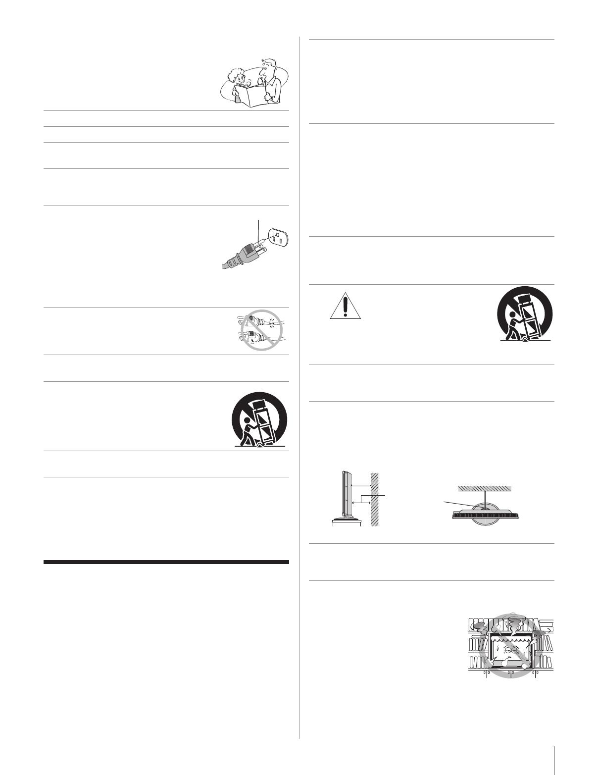
22) Never block or cover the slots or openings in the TV
cabinet back, bottom, and sides. Never place the TV:
on a bed, sofa, rug, or similar
surface;
too close to drapes, curtains,
or walls; or
in a confined space such as
a bookcase, built-in cabinet,
or any other place with poor
ventilation.
The slots and openings are provided to protect the TV from
overheating and to help maintain reliable operation of the
TV. Leave a space of at least 4 (four) inches around the TV.
(continued)
.
Grounding
prong
23) Always place the back of the television at least four (4)
inches away from any vertical surface (such as a wall) to
allow proper ventilation.
24) Never allow anything to rest on or roll over the power
cord, and never place the TV where the power cord is
subject to wear or abuse.
25) Never overload wall outlets and extension cords.
26) Always operate this equipment from a 120 VAC, 60 Hz
power source only.
27) Always make sure the antenna system is properly
grounded to provide adequate protection against voltage
surges and built-up static charges (see Section 810 of
the National Electric Code).
Antenna lead-in wire
Antenna discharge unit
(NEC Section 810-20)
Grounding conductors
(NEC Section 810-21)
Power service grounding electrode
system (NEC Art 250 Part-H)
Ground clamp
Electric service equipment
Ground clamps
28)
DANGER: RISK OF SERIOUS
PERSONAL INJURY OR DEATH!
Use extreme care to make sure you are never in a
position where your body (or any item you are in contact
with, such as a ladder or screwdriver) can accidentally
touch overhead power lines. Never locate the antenna
near overhead power lines or other electrical circuits.
Never attempt to install any of the following during
lightning activity: a) an antenna system; or b) cables,
wires, or any home theater component connected to
an antenna or phone system.
Care
For better performance and safer operation of your TOSHIBA
TV, follow these recommendations and precautions:
29) If you use the TV in a room whose temperature is 32 °F
(0 °C) or below, the picture brightness may vary until the
LCD warms up. This is not a sign of malfunction.
30) Always unplug the TV before
cleaning. Gently wipe the
display panel surface (the TV
screen) using a dry, soft cloth
only (cotton, flannel, etc.). A
hard cloth may damage the
surface of the panel. Avoid
contact with alcohol, thinner, benzene, acidic or alkaline
solvent cleaners, abrasive cleaners, or chemical cloths,
which may damage the surface. Never spray volatile
compounds such as insecticide on the cabinet. Such
products may damage or discolor the cabinet.
31)
WARNING:
RISK OF ELECTRIC SHOCK!
Never spill liquids or push objects of any kind into the TV
cabinet slots.
32) While it is thundering, do not touch the connecting cables
or apparatus.
33) For added protection of your TV from lightning and power
surges, always unplug the power cord and disconnect
the antenna from the TV if you leave the TV unattended
or unused for long periods of time.
34) During normal use, the TV may make occasional
snapping or popping sounds. This is normal, especially
when the unit is being turned on or off. If these sounds
become frequent or continuous, unplug the power cord
and contact a Toshiba Authorized Service Center.
35)
DANGER: RISK OF
SERIOUS PERSONAL
INJURY OR DEATH!
Never strike the screen with a sharp
or heavy object.
36) The LCD screen of this product can be damaged by
ultraviolet radiation from the sun. When selecting a
location for the television, avoid locations where the
screen may be exposed to direct sunlight, such as in
front of a window.
Never touch, press, or place anything on the LCD
screen. These actions will damage the LCD screen.
If you need to clean the LCD screen, follow the
instructions in item 30 on this page.
Service
37)
WARNING:
RISK OF ELECTRIC SHOCK!
Never attempt to service the TV yourself. Opening and
removing the covers may expose you to dangerous
voltage or other hazards. Failure to follow this WARNING
may result in death or serious injury. Refer all servicing
not specified in this manual to a Toshiba Authorized
Service Center.
38) If you have the TV serviced:
Ask the service technician to use only replacement
parts specified by the manufacturer.
Upon completion of service, ask the service technician
to perform routine safety checks to determine that the
TV is in safe operating condition.
39) The cold cathode fluorescent lamp in the LCD panel
contains a small amount of mercury.
When the TV reaches the end of its useful life, dispose
of the used TV by the approved method for your area, or
ask a qualified service technician to properly dispose of
the TV.
Note: The lamp(s) inside this product contain
mercury. Disposal may be regulated due to
environmental considerations. For disposal or
recycling information, contact your local authorities or the
Electronics Industries Alliance (www.eiae.org).
Choosing a location for your LCD TV
To Display your LCD TV on the included Pedestal
Stand:
Observe the following safety precautions:
1) Read and Follow the pedestal assembly instructions.
CAUTION:
Before beginning pedestal assembly, carefully
lay the front of the LCD Panel face down on a flat, cushioned
surface such as a quilt or blanket. Leave the bottom of the unit
protruding over the edge of the surface and assemble the pedestal
as indicated below.
Note:
Extreme care should always be used when attaching
the pedestal stand to avoid damage to the LCD panel.
2) Place the TV on a sturdy, level surface that can support the
weight of the TV.
3) Be sure to secure the TV to a wall, pillar, surface, or other
immovable structure. (
item 20, page 3).
To Display your LCD TV using a Wall Bracket:
If you decide to wall mount your LCD TV, always use a UL-
listed wall bracket appropriate for the size and weight of the
LCD TV (
page 2) :
1)
CAUTION:
Two people are required for installation.
2) Unplug and remove any cables and/or other component
connectors from the rear of the TV.
3) Follow the instructions provided with your wall bracket.
Before proceeding, make sure the appropriate bracket(s) are
attached to the wall and the back of the TV as described in the
instructions provided with the wall bracket.
4) Remove the screws of the VESA Mounting Pattern show in
the right diagram.
5) After attaching the appropriate bracket(s) to the wall and the
back of the TV, remove the pedestal stand from the TV as
described below.
6) VESA Mounting Pattern
TV Size Hole Pattern(VxH) Screw Size
26” 100x200 mm M4
32”/ 37”/ 42” 200x400 mm M6
(unit in mm)
Removing the Pedestal Stand
1) Carefully lay the front of the unit face down on a flat,
cushioned surface such as a quilt or blanket. Leave the stand
protruding over the edge of the surface.
Note:
Extreme care should always be used when removing
the pedestal stand to avoid damage to the LCD panel.
2) Remove the screws shown in the right diagram . This will
allow removal of the pedestal stand.
3) Once you have removed all screws holding the pedestal stand
in place, remove the pedestal stand from the TV.
Six screws
Four screws
Four screws
6” TV
”/ 7” TV
” TV
VESA Mounting Pattern
6
FCC Declaration of Conformity
Compliance Statement
(Part 15):
The Toshiba 26AV500U, 32AV500U, 37AV50U, 37AV500U
and 42AV500U Televisions comply with Part 15 of the FCC
rules.
Operation is subject to the following two conditions: (1) this
device may not cause harmful interference, and (2) this device
must accept any interference received, including interference that
may cause undesired operation.
The party responsible for compliance to these rules is:
Toshiba America Consumer Products, L.L.C.
82 Totowa Rd. Wayne, NJ 07470.
Ph: 1-800-631-3811
Note: This equipment has been tested and found to comply
with the limits for a Class B digital device, pursuant to Part
15 of the FCC rules. These limits are designed to provide
reasonable protection against harmful interference in a
residential installation. This equipment generates, uses, and
can radiate radio frequency energy and, if not installed and
used in accordance with the instructions, may cause harmful
interference to radio communications. However, there is
no guarantee that interference will not occur in a particular
installation. If this equipment does cause harmful interference
to radio or television reception, which can be determined by
removing and applying power to the equipment, the user is
encouraged to try to correct the interference by one or more
of the following measures:
Reorient or relocate the receiving antenna.
Increase the separation between the equipment and the
receiver.
Connect the equipment into an outlet on a circuit different
from that to which the receiver is connected.
Consult the dealer or an experienced radio/TV technician for
help.
Caution: Changes or modifications to this equipment not
expressly approved by Toshiba could void the user’s authority
to operate this equipment.
Important notes about your LCD
TV
The following symptoms are technical limitations of LCD
Display technology and are not an indication of malfunction;
therefore, Toshiba is not responsible for perceived issues
resulting from these symptoms.
An afterimage (ghost) may appear on the screen if a fixed,
nonmoving image is displayed for a long period of time. The
afterimage is not permanent and will disappear in a short
period of time.
The LCD panel contained in this TV is manufactured using
an extremely high level of precision technology; however,
there may be an occasional pixel (dot of light) that does not
operate properly (does not light, remains constantly lit, etc.).
This is a structural property of LCD technology, is not a
sign of malfunction, and is not covered under your warranty.
Such pixels are not visible when the picture is viewed from a
normal viewing distance.
Note: Interactive video games that involve shooting a “gun”
type of joystick at an on-screen target may not work with this
TV.
Trademark Information
Manufactured under license from Dolby Laboratories.
Dolby and the double-D symbol are registered trademarks of
Dolby Laboratories.
HDMI, the HDMI logo and High-Definition Multimedia Interface are
trademarks or registered trademarks of HDMI Licensing LLC.
1)
2)
7
Contents
Important Safety Instructions .......................
Installation, Care, and Service .....................
Chapter 1: Introduction ..............................
8
Welcome to Toshiba .................................................................8
Features of your new TV .........................................................8
Overview of steps for installing, setting up, and using
your new TV ..................................................................... 9
TV front and side panel controls and connections ................10
TV back panel connections ....................................................11
Chapter : Connecting your TV ....................
1
Overview of cable types ........................................................12
About the connection illustrations .........................................12
Connecting a VCR and antenna or Cable TV
(no Cable box)................................................................13
Connecting a VCR with S-video and a cable box ................. 14
Connecting a DVD player with ColorStream
®
(component
video), a VCR, and a satellite receiver ............................15
Connecting a camcorder ........................................................16
Connecting an HDMI™ or DVI device to the HDMI input ..17
Connecting a digital audio system .........................................18
Connecting an audio system ..................................................18
Connecting a personal computer (PC) ................................... 19
Chapter : Using the remote control ..............
0
Preparing the remote control for use .....................................20
Installing the remote control batteries ...................................20
Remote control effective range ..............................................20
Learning about the remote control .........................................21
Using the remote control to control your other devices ........22
Remote Control functional key chart .....................................23
Programming the remote control to control your other
devices .............................................................................24
Remote control codes ............................................................ 25
Chapter : Menu layout and navigation ..........
7
Main menu layout ..................................................................27
Navigating the menu system ..................................................28
Chapter : Setting up your TV ......................
9
Selecting the menu language .................................................29
Configuring the antenna input source for the
ANT/CABLE terminal ....................................................29
Viewing the digital signal meter ............................................29
Viewing the system status ...................................................... 29
Programming channels into the TV’s channel memory ........30
Programming channels automatically .............................30
Manually adding channels in the channel memory .........30
Manually deleting channels in the channel memory .......31
Channel Labels Menu .....................................................31
Chapter 6: Using the TV’s features ................

Selecting the video input source to view ...............................32
Tuning channel ..................................................................... 32
Favorites Browser ........................................................... 32
Tuning to the next programmed channel ........................ 32
Tuning to a specific channel (programmed or
unprogrammed) ........................................................32
Switching between two channels using Channel Return 32
Selecting the picture size .......................................................33
Adjusting the picture .............................................................34
Selecting the picture mode ..............................................34
Adjusting the picture quality ........................................... 35
Using the closed caption mode ..............................................35
Base closed captions .......................................................35
Digital CC Settings ........................................................36
Adjusting the audio ................................................................ 36
Muting the sound ............................................................ 36
Selecting stereo/SAP broadcasts .....................................36
Adjusting the audio quality .............................................37
Selecting the optical output format .................................38
Using the Parental Control menu ...........................................38
Entering the PIN code .....................................................38
Changing your PIN code ................................................. 39
If you still cannot remember your PIN code ................... 39
Blocking TV programs and movies by rating (V-Chip) .. 39
Using the PC settings feature.................................................40
Setting the PC Audio ............................................................. 41
Setting the sleep timer ........................................................... 41
Setting the time zone ............................................................. 42
Displaying TV status information ......................................... 42
Understanding the auto power off feature ............................. 42
Understanding the last mode memory feature .......................42
Chapter 7: Using the TV’s advanced features ...

Using the advanced picture settings features ......................... 43
Using Dynamic Contrast .................................................43
Using DynaLight™ .........................................................43
Backlight Adjustment...................................................... 43
Using the static gamma feature .......................................44
Using the auto aspect ratio feature .................................. 44
Selecting the color temperature ......................................45
Using MPEG Noise Reduction .......................................45
Using CableClear
®
digital noise reduction .....................45
Chapter 8: Troubleshooting .........................
6
General troubleshooting ........................................................46
LED indications .....................................................................47
Chapter 9: Appendix .................................
8
Specifications .........................................................................48
Limited United States Warranty
for LCD Televisions 26” and Larger
.......................
50
Limited Canadian Warranty
for Toshiba Brand Flat Panel Televisions
..................
51
8
Welcome to Toshiba
Thank you for purchasing this Toshiba LCD TV, one of
the most innovative LCD TVs on the market. This digital
television is capable of receiving analog basic, digital basic
and digital unencrypted cable television programming
by direct connection to a cable system providing such
programming. Certain advanced and interactive digital
cable services such as video-on-demand, a cable operator's
enhanced program guide and data-enhanced television
services may require the use of a set-top box. For more
information call your local cable operator.
Features of your new TV
The following are just a few of the many exciting features of
your new Toshiba widescreen, integrated HD, LCD TV:
Integrated digital tuning (8VSB ATSC and QAM)
eliminates the need for a separate digital converter set-top
box (in most cases).
Two HDMI™ digital, high-definition multimedia
interfaces 1080i input support (page 17).
HDMI™ (V.1.3 with Lip Sync)
Lip-Sync allows HDMI source devices to accurately
perform synchronization automatically.
Two sets of ColorStream
®
HD high-resolution component
video inputs (page 15).
Digital Audio Out optical audio connection with Dolby
®
Digital optical output format (page 18).
CableClear
®
digital picture noise reduction (page 45).
PC IN (Analog RGB) computer terminal (page 19).
Channel Labels allows you to put the Call Letters (e.g.
ABC, HBO, etc.) on the screen along with the station
numbers, so you always know what you’re watching
(page 31).
Chapter 1: Introduction
9
Overview of steps for installing,
setting up, and using your new TV
Follow these steps to set up your TV and begin using its many
exciting features.
Carefully read the important safety, installation, care,
and service information. Keep this manual for future
reference.
Observe the following when choosing a location for the
TV:
Read “Important notes about your LCD TV”
(page 6).
Place the TV on the floor or a sturdy, level, stable
surface that can support the weight of the unit. Secure
the TV to a wall, pillar, or other immovable structure
( page 3).
Place the TV in a location where light does not reflect
on the screen.
Place the TV far enough from walls and other objects
to allow proper ventilation. Inadequate ventilation may
cause overheating, which will damage the TV. THIS
TYPE OF DAMAGE IS NOT COVERED UNDER
THE TOSHIBA WARRANTY.
Do not plug in any power cords until AFTER you have
connected all cables and devices to your TV.
BEFORE connecting cables or devices to the TV, learn
the functions of the TV’s connections and controls
(pages 10–11).
Connect your other electronic device(s) to the TV
(pages 12–19).
Install the batteries in the remote control (page 20).
See “Learning about the remote control” (page 21) for
an overview of the buttons on the remote control.
Program the remote control to operate your other
device(s) (pages 22–26).
AFTER connecting all cables and devices, plug in the
power cords for your TV and other devices. The LED
indication will be red when the TV is on standby mode.
The LED indication will be green when press POWER
on the TV control panel or remote control to turn on the
TV.
1�
2�
3�
4�
5�
6�
7�
8�
9�
See “Menu layout and navigation” for a quick overview
of navigating the TV’s menu system (page 27).
Program channels into the TV’s channel memory
(page 30).
For details on using the TV’s features, see Chapters 6
and 7.
For help, refer to the Troubleshooting Guide, Chapter 8.
For technical specifications and warranty information,
see Chapter 9.
Enjoy your new TV!
10�
11�
12�
13�
14�
15�
Chapter 1: Introduction
10
TV front and side panel controls and connections
POWER
POW E R
3
3
4
5
6
7
8
9
10
6
10
45
9
78
1 2
Green and Red LEDs
Green = Power On
Red = Power off (standby mode)
See “LED indications” on page 47 for additional
information.
Remote sensor — Point the remote control toward this
remote sensor ( “Remote control effective range” on
page 20).
VIDEO 2 IN — The side panel A/V connections are
referred to as “VIDEO 2” and include standard A/V
connections.
POWER — Press to turn the TV on and off.
MENU (ENTER) — Press to access the menu system
(pages 27–28). When a menu is on-screen, the MENU
button on the TV’s control panel functions as the ENTER
button.
CHANNEL pqWhen no menu is on-screen, these
buttons change the channel (programmed channels only;
page 30).
1�
2�
3�
4�
5�
6�
VOLUME tu — These buttons adjust the volume level.
INPUT — Repeatedly press to change the source you
are viewing (ANT, VIDEO 1, VIDEO 2, ColorStream
HD1, ColorStream HD2, HDMI 1, HDMI 2, PC).
EXIT — Press to instantly close an on-screen menu.
ARROWS pqtuWhen a menu is on-screen, these
buttons function as up/down/left/right menu navigation
buttons.
7�
8�
9�
10�
6”/ ”/ 7” TV Control panel
” TV Control panel
TV front
6”/ ”/ 7” TV
Left side panel
” TV
Right side panel
Chapter 1: Introduction
11
TV back panel connections
For an explanation of cable types and connections, see pages 12–19.
HDMI™ IN — High-Definition Multimedia Interface
input receives digital audio and uncompressed digital
video from an HDMI device or uncompressed digital
video from a DVI device. Also see item 2. HDMI
connection is necessary to receive 1080i signals.
PC IN (AUDIO)— PC audio input terminals are shared
with HDMI 1 analog audio input terminals.
PC IN (RGB)— For use when connecting a personal
computer.
Service — For service use only. Used for updating the
television’s firmware.
ColorStream
®
HD 1 and ColorStream
®
HD 2
Two sets of ColorStream
®
high-definition component
video inputs (with standard stereo audio inputs) for
connecting devices with component video output, such as
a Toshiba DVD player with ColorStream
®
.
Note: Component video cables carry only video
information; separate audio cables are required for a
complete connection.
1�
2�
3�
4�
5�
Audio OUTAnalog audio outputs for connecting an
audio amplifier.
VIDEO 1 IN — Standard (composite) video and standard
audio inputs plus optional S-video inputs for connecting
devices with composite video or S-video output.
Note: Standard (composite) video and S-video cables
carry only video information; separate audio cables are
required for a complete connection.
Digital Audio OUT — Optical audio output in Dolby
Digital or PCM (pulse-code modulation) format for
connecting an external Dolby Digital decoder, amplifier,
A/V receiver, or home theater system with optical audio
input.
ANT/CABLEAntenna input that supports analog
(NTSC) and digital (ATSC) off-air antenna signals and
analog and digital Cable TV (QAM) signals.
HDMI, the HDMI logo and High-Definition Multimedia Interface
are trademarks or registered trademarks of HDMI Licensing LLC.
Manufactured under license from Dolby Laboratories.
Dolby and the double-D symbol are registered trademarks of Dolby
Laboratories.
6�
7�
8�
9�
AV00U
7AV0U
7AV00U
AV00U
6”TV ”/ 7” TV
” TV
6AV00U
Power cord
Power cord
1
Overview of cable types
Cables can be purchased from most stores that sell audio/
video devices. Before purchasing any cables, be sure of con-
nector types required by your devices and the length of each
cable.
Coaxial (F-type) cable
Coaxial (F-type) cable is used for connecting your antenna,
cable TV service, and/or cable converter box to the ANT/
CABLE input on your TV.
Standard A/V cables (red/white/yellow)
Standard A/V cables (composite video) usually come in sets
of three, and are for use with video devices with analog audio
and composite video output. These cables (and the related
inputs on your TV) are typically color-coded according to
use: yellow for video, red for stereo right audio, and white for
stereo left (or mono) audio.
S-video cable
S-video cable is for use with video devices with S-video
output. Separate audio cables are required for a complete
connection.
Note: An S-video cable provides better picture performance
than a composite video cable. If you connect an S-video cable,
be sure to disconnect the standard (composite) video cable or
the picture performance will be unacceptable.
Component video cables (red/green/blue)
Component video cables come in sets of three and are for
use with video devices with component video output.
(ColorStream
®
is Toshiba’s brand of component video.) These
cables are typically color-coded red, green, and blue. Separate
audio cables are required for a complete connection.
Note: Component video cables provide better picture
performance than a standard (composite) video or S-video
cable.
HDMI™ cable (with HDMI Logo “ ”)
HDMI (High-Definition Multimedia Interface) cable is for
use with devices with an HDMI output. An HDMI cable de-
livers digital audio and video in its native format. This cable
carries both video and audio information; therefore, separate
audio cables are not required for a complete HDMI device
connection (page 17 and page 19).
Note: HDMI cable provides better picture performance than a
standard (composite) video or S-video cable.
Optical audio cable
Optical audio cable is for connecting receivers with Dolby
Digital or PCM (pulse-code modulation) optical audio input
to the TV’s DIGITAL AUDIO OUT terminal (page 18).
Analog RGB (15-pin) computer cable
Analog RGB (15-pin) computer cable is for connecting a PC
to the TV’s PC IN terminal (page 19).
About the connection illustrations
You can connect different types and brands of devices to your
TV in several different configurations. The connection il-
lustrations in this manual are representative of typical device
connections only. The input/output terminals on your devices
may differ from those illustrated herein. For details on con-
necting and using your specific devices, refer to each device’s
owner’s manual.
Chapter 2: Connecting your TV
1
Connecting a VCR and antenna or Cable TV (no Cable box)
IN from ANT
VIDEO AUDIO
OUT to TV
L R
R
L
OUT
IN
CH 3
CH 4
You will need:
coaxial cables
standard A/V cables
For better picture performance, if your VCR has S-video,
use an S-video cable (plus the audio cables) instead of
the standard video cable. Do not connect both types of
video cable to VIDEO 1 at the same time or the picture
performance will be unacceptable.
If you have a mono VCR, connect L/MONO on the TV
to your VCR’s audio out terminal using the white audio
cable only.
To view the antenna or Cable signal:
Select the ANT video input source on the TV.*
To view the VCR:
Turn ON the VCR. Select the VIDEO 1 video input source on
the TV.*
To select the video input source, press
INPUT
on the remote
control (
page 21). To program the TV remote control to operate
other devices, see Chapter 3.
The unauthorized recording, use, distribution, or revision of
television programs, videotapes, DVDs, and other materials
is prohibited under the Copyright Laws of the United States
and other countries, and may subject you to civil and criminal
liability.
*
Stereo VCR
Chapter 2: Connecting your TV
1
Connecting a VCR with S-video and a cable box
An S-video connection will provide better picture performance than a standard (composite) video cable.
IN from ANT
VIDEO AUDIO
OUT to TV
L R
R
L
OUT
IN
CH 3
CH 4
IN
OUT
CH 3
CH 4
You will need:
coaxial cables
S-video cable
Do not connect both types of video cable to VIDEO 1
at the same time or the picture performance will be
unacceptable.
standard audio cables
If you have a mono VCR, connect L/MONO on the TV
to your VCR’s audio out terminal using the white audio
cable only.
Note: When you use a Cable box, you may not be able to use
the remote control to program or access certain features on
the TV.
To view basic and premium Cable channels:
Turn OFF the VCR. Select the ANT video input source on
the TV.* Tune the TV to channel 3 or 4 (whichever channel
the Cable box output is set to). Use the Cable box controls to
change channels.
To view the VCR:
Turn ON the VCR. Select the VIDEO 1 video input source on
the TV.*
To select the video input source, press
INPUT
on the remote
control (
page 21). To program the TV remote control to operate
other devices, see Chapter 3.
The unauthorized recording, use, distribution, or revision of
television programs, videotapes, DVDs, and other materials
is prohibited under the Copyright Laws of the United States
and other countries, and may subject you to civil and criminal
liability.
*
From Cable TV
Cable box
Stereo VCR
Chapter 2: Connecting your TV
1
Connecting a DVD player with ColorStream
®
(component video), a VCR,
and a satellite receiver
Your TV has two sets of ColorStream
®
(component video) inputs.
IN from ANT
VIDEO AUDIO
OUT to TV
L R
R
L
OUT
IN
CH 3
CH 4
VIDEO
OUT
COMPONENT VIDEO
P
B
P
R
Y
AUDIO
OUT
L
R
S-VIDEO
OUT
S-VIDEO
OUT
VIDEO
OUT
AUDIO
OUT
COMPONENT VIDEO
L
R
Satellite
IN
P
B
P
R
Y
You will need:
coaxial cables
standard A/V cables
For better picture performance, if your VCR has S-video,
use an S-video cable (plus the audio cables) instead of
the standard video cable. Do not connect both types of
video cable to VIDEO 1 at the same time or the picture
performance will be unacceptable.
If you have a mono VCR, connect L/MONO on the TV
to your VCR’s audio out terminal using the white audio
cable only.
standard audio cables
component video cables
You can connect the component video cables (plus
audio cables) from the DVD player or satellite receiver to
either set of ColorStream terminals on the TV (HD 1 or
HD 2). The ColorStream HD 1 and HD 2 terminals can
be used with Progressive (480p, 720p) and Interlaced
(480i, 1080i) scan systems. A 1080i signal will provide
the best picture performance (1080p is not supported).
If your DVD player or satellite receiver does not have
component video, connect a standard A/V cable to
VIDEO 2 on the side panel. If your DVD player has HDMI
video, see page 17.
To view antenna or Cable channels:
Select the ANT video input source on the TV.*
To view the DVD player:
Turn ON the DVD player. Select the ColorStream HD 1
video input source on the TV.*
To view satellite programs using the component
video connections:
Turn on the satellite receiver. Select the ColorStream HD 2
video input source on the TV.*
To view the VCR or view and record antenna chan-
nels:
Turn ON the VCR. Tune the VCR to the channel you want to
watch. Select the VIDEO 1 video input source on the TV.*
To record a TV program while watching a DVD:
Turn ON the VCR. Tune the VCR to the channel to record.
Select the ColorStream HD 1 video input source on the TV*
to view the DVD.
To select the video input source, press
INPUT
on the remote
control (
page 21). To program the TV remote control to operate
other devices, see Chapter 3.
The unauthorized recording, use, distribution, or revision of
television programs, videotapes, DVDs, and other materials
is prohibited under the Copyright Laws of the United States
and other countries, and may subject you to civil and criminal
liability.
*
From antenna
DVD player with component video
Stereo VCR
Satellite receiver with component video
From satellite dish
Chapter 2: Connecting your TV
16
Connecting a camcorder
You will need:
standard A/V cables
For better picture performance, if your camcorder has
S-video, connect an S-video cable (plus the audio cables)
to VIDEO 1 on the TV back instead of the VIDEO 2 on the
TV side panel.
To view the camcorder video:
Select the VIDEO 2 video input source on the TV.*
To select the video input source, press
INPUT
on the remote
control (
page 21). To program the TV remote control to operate
other devices, see Chapter 3.
*
" TV
6"/ "/ 7" TV
Camcorder
Camcorder
Chapter 2: Connecting your TV
17
Connecting an HDMI™ or DVI
device to the HDMI input
The HDMI input on your TV receives digital audio and
uncompressed digital video from an HDMI source device,
or uncompressed digital video from a DVI (Digital Visual
Interface) source device. This TV is able to connect with
HDMI devices. But it is possible that same HDMI devices
may not operate properly with this TV.
This input is designed to accept HDCP (High-Bandwidth
Digital-Content Protection) program material in digital form
from EIA/CEA-861-D–compliant
[1]
consumer electronic
devices (such as a set-top box or DVD player with HDMI or
DVI output).
The HDMI 1 input can accept and display VGA, SVGA,
XGA, 480i (60Hz), 480p (60Hz), 720p (60Hz), and 1080i
(60Hz) signal formats. For detailed signal specifications, see
page 49.
Supported Audio format: Linear PCM, sampling rate 32/44.1/
48 kHz
Note: To connect a PC to the HDMI input, see page 19.
To connect an HDMI device, you will need:
one HDMI cable (type A connector) per HDMI device
For proper operation, it is recommended that you use an
HDMI cable with the HDMI Logo ( ).
To display an 1080i/60Hz signal format, you will need a
Category 2 cable. Conventional HDMI/DVI cable may
not work properly.
HDMI cable transfers both video and audio. Separate
analog audio cables are not required (see illustration).
VIDEO AUDIO
L R
R
L
IN
OUT
IN
HDMI OUT
To view the HDMI device video:
Select the HDMI 1 or HDMI 2 video input source on the TV.*
To select the video input source, press
INPUT
on the remote
control (
page 21). To program the TV remote control to operate
other devices, see Chapter 3.
*
To connect a DVI device, you will need:
one HDMI-to-DVI adapter cable (HDMI type A connector)
per DVI device
For proper operation, the length of an HDMI-to-DVI
adapter cable should not exceed 9.8 ft (3m). The
recommended length is 6.6 ft (2m).
one pair of standard analog audio cables per DVI device
An HDMI-to-DVI adapter cable transfers video only.
Separate analog audio cables are required (see
illustration).
VIDEO AUDIO
L R
R
L
OUT
IN
DVI/ HDCP
OUT
IN
Note: To ensure that the HDMI or DVI device is reset properly,
it is recommended that you follow these procedures:
When turning on your electronic components, turn on the
TV first, and then the HDMI or DVI device.
When turning off your electronic components, turn off the
HDMI or DVI device first, and then the TV.
[1] EIA/CEA-861-D compliance covers the transmission of
uncompressed digital video with high-bandwidth digital
content protection, which is being standardized for reception
of highdefinition video signals. Because this is an evolving
technology, it is possible that some devices may not operate
properly with the TV.
HDMI, the HDMI logo and High-Definition Multimedia Interface are
trademarks or registered trademarks of HDMI Licensing LLC.
HDMI device
DVI device
Chapter 2: Connecting your TV
18
Connecting a digital audio system
The TV’s DIGITAL AUDIO OUT terminal outputs a Dolby
®
*
Digital or 2-channel down-mixed PCM (pulse-code
modulation) signal for use with an external Dolby
®
Digital
decoder or other external audio system with optical audio
input.
You will need:
optical audio cable (Use an optical audio cable that has
the larger “TosLink” connector and not the smaller “mini-
optical” connector.)
LINE IN
Optical
Audio IN
L R
To control the audio:
Turn on the TV and the digital audio device.
Press on the TV’s remote control and open the Audio
menu.
In the Optical Output Format field, select either
Dolby Digital or PCM, depending on your device
( “Selecting the optical audio output format” on
page 38).
1�
2�
3�
Note:
Some audio systems may not be compatible with Dolby
Digital bitstream signals. Older audio systems that are not
compatible with standard optical out signals may not work
properly, creating a high noise level that may damage
speakers. THIS DAMAGE IS NOT COVERED BY YOUR
WARRANTY.
The DIGITAL AUDIO OUT terminal may not output some
digital audio sources because of copy restrictions.
Manufactured under license from Dolby Laboratories. Dolby,
and the double-D symbol are registered trademarks of Dolby
Laboratories.
Connecting an audio system
This connection allows you to use external speakers with an
external analog audio amplifier to adjust the sound level.
You will need:
standard audio cables
LINE IN
L R
To control the audio:
Turn on the TV and the stereo amplifier.
Set up a optimum volume level of the stereo amplifier.
Then you can adjust the sound volume level from the
TV’s volume control or the amplifier’s volume control.
Menu item of Speakers can turn to OFF to mute the TV’s
built in speakers.
*
1�
2�
3�
Dolby Digital decoder or
other digital audio system
Analog audio amplier
Chapter 2: Connecting your TV
19
Connecting a personal computer
(PC)
With either the PC IN or HDMI connection, you can watch
your computer’s display on the TV and hear the sound from
the TV’s speakers.
To connect a PC to the PC IN terminal on the TV:
When connecting a PC to the PC IN terminal on the TV,
use an analog RGB (15-pin) computer cable and a PC audio
cable.
To use a PC, set the monitor output resolution on the PC
before connecting it to the TV. The following signals can
be displayed:
Format Resolution V. Frequency
VGA 640 × 480 60Hz
SVGA 800 × 600 60Hz
XGA 1024 × 768 60Hz
WXGA 1280 × 768 60Hz
WXGA 1360 × 768 60Hz
Other formats or non-standard signals will not be displayed
correctly.
To display the optimum picture, use the PC setting feature
( “Using the PC settings feature” on page 40).
Note:
The PC audio input terminals on the TV are shared with the
HDMI 1 analog audio input terminals ( page 41).
Some PC models cannot be connected to this TV.
An adapter is not needed for computers with a compatible
mini D-sub15-pin terminal.
An adapter is not needed for computers with a compatible
mini D-sub15-pin terminal.
Depending on the DVD’s title and the specifications of the
PC on which you are playing the DVD-Video, some scenes
may be skipped or you may not be able to pause during
multi-angle scenes.
Signal names for mini D-sub 15-pin connector
Pin No.
Signal
name
Pin No.
Signal
name
Pin No.
Signal
name
1 R 6 Ground 11 NC
2 G 7 Ground 12 NC
3 B 8 Ground 13 H-sync
4 NC* 9 NC 14 V-sync
5 NC 10 Ground 15 NC
*
NC=Not connected
If connecting a certain PC model that signal is particular,
the PC signal may not be detected correctly.
To connect a PC to the HDMI terminal on the TV:
When connecting a PC to the HDMI terminal on the TV, use
an HDMI-to DVI adapter cable and analog audio cables ( PC
IN AUDIO port just shared with DVI signal from HDMI1
port only). If connecting a PC with an HDMI terminal, use an
HDMI cable (type A connector). Separate analog cables are
not necessary ( page 17).
The HDMI 1 input can accept and display VGA, SVGA,
XGA, 480i (60Hz), 480p (60Hz), 720p (60Hz), and 1080i
(60Hz) signal formats. For detailed signal specifications, see
page 49.
Note:
The edges of the images may be hidden.
If connecting a certain PC model that signal is particular,
the PC signal may not be detected correctly.
Computer
PC audio
output
PC audio
cable
Conversion adapter
(if necessary)
Computer
PC audio
output
PC audio
cable
20
Preparing the remote control for
use
Your TV remote control can operate your TV and many other
devices such as cable converter boxes, satellite receivers,
VCRs, DVD players, and HTIBs (home theater in a box),
even if they are different brands.
If you have a Toshiba device:
Your TV remote control is preprogrammed to operate most
Toshiba devices ( page 24).
If you have a non-Toshiba device or a Toshiba device
that the remote control is not preprogrammed to
operate:
You can program the TV remote control so it will operate the
other device (pages 22–26).
Installing the remote control
batteries
Remove the battery cover from the back of the remote
control.
Squeeze tab
and lift cover.
Install two “AAA” size batteries, making sure to match
the + and – signs on the batteries to the signs on the
battery compartment.
Reinsert the battery cover in the remote control until the
tab snaps.
Caution:
Dispose of batteries in a designated disposal area. Never
throw batteries into a fire.
Attention should be drawn to the environmental aspects of
battery disposal.
Never mix battery types or combine used batteries with
new ones.
Batteries shall not be exposed to excessive heat such as
sunshine, fire or the like.
Note:
Be sure to use AAA size batteries.
Dispose of batteries in a designated disposal area.
Batteries should always be disposed of with the
1
2
3
environment in mind. Always dispose of batteries in
accordance with applicable laws and regulations.
If the remote control does not operate correctly, or if the
operating range becomes reduced, replace batteries with
new ones.
When necessary to replace batteries in the remote control,
always replace both batteries with new ones. Never mix
battery types or use new and used batteries in combination.
Always remove batteries from the remote control if they
are dead or if the remote control is not to be used for an
extended period of time. This will prevent battery acid from
leaking into the battery compartment.
Remote control effective range
For optimum performance, aim the remote control directly
at the TV and make sure there is no obstruction between the
remote control and the TV.
16.4 ft (5m)
Chapter 3: Using the remote control
Point remote control
toward remote sensor
on front of TV.
1 / 1

Toshiba 26AV500U User manual

Category
LCD TVs
Type
User manual

Ask a question and I''ll find the answer in the document

Finding information in a document is now easier with AI

Ask the document