Page is loading ...

Centrifugal inline fan
USER’S MANUAL
VKMz 100
VKMz 125
VKMz 150
VKMSz 150
VKMz 160
VKMSz 160
VKMz 200 Q
VKMz 200
VKMz 250 Q
VKMz 250
VKMz 315
VKMSz 315

2
VKMz
www.ventilation-system.com
CONTENTS
This user’s manual is a main operating document intended for technical, maintenance, and operating staff.
The manual contains information about purpose, technical details, operating principle, design, and installation of the VKMz unit and all
its modifications.
Technical and maintenance staff must have theoretical and practical training in the field of ventilation systems and should be able to
work in accordance with workplace safety rules as well as construction norms and standards applicable in the territory of the country.
Contents .............................................................................................................................................................................................. 2
Safety requirements ..................................................................................................................................................................... 2
Purpose ................................................................................................................................................................................................ 4
Delivery set ........................................................................................................................................................................................ 4
Designation key .............................................................................................................................................................................. 4
Technical data .................................................................................................................................................................................. 5
Design and operating principle ........................................................................................................................................... 6
Mounting and set-up .................................................................................................................................................................. 6
Connection to power mains .................................................................................................................................................. 7
Technical maintenance .............................................................................................................................................................. 8
Storage and transportation regulations .......................................................................................................................... 8
Manufacturer’s warranty ........................................................................................................................................................... 9
Certificate of acceptance .......................................................................................................................................................... 11
Seller information .......................................................................................................................................................................... 11
Installation certificate .................................................................................................................................................................. 11
Warranty card ................................................................................................................................................................................... 11

3
www.ventilation-system.com
SAFETY REQUIREMENTS
• Please read the user’s manual carefully prior to installing and operating the unit.
• All user’s manual requirements as well as the provisions of all the applicable local and national
construction, electrical, and technical norms and standards must be observed when installing
and operating the unit.
• The warnings contained in the user’s manual must be considered most seriously since they
contain vital personal safety information.
• Failure to follow the rules and safety precautions noted in this user’s manual may result in an
injury or unit damage.
• After a careful reading of the manual, keep it for the entire service life of the unit.
• While transferring the unit control, the user’s manual must be turned over to the receiving
operator.
UNIT INSTALLATION AND OPERATION SAFETY PRECAUTIONS
• Disconnect the unit from power mains prior to any installation operations.
• Unpack the unit with care.
• The unit must be grounded!
• While installing the unit, follow the safety regulations specific to the use of electric tools.
• Do not change the power cable length at your own discretion.
• Do not bend the power cable.
• Avoid damaging the power cable.
• Do not put any foreign objects on the power cable.
• Do not lay the power cable of the unit in close proximity to heating equipment.
• Do not use damaged equipment or cables when connecting the unit to power mains.
• Do not operate the unit outside the temperature range stated in the user’s manual.
• Do not operate the unit in aggressive or explosive environments.
• Do not touch the unit controls with wet hands.
• Do not carry out the installation and maintenance operations with wet hands.
• Do not wash the unit with water.
• Protect the electric parts of the unit against ingress of water.
• Do not allow children to operate the unit.
• The unit is allowed to be used by children aged from 8 years oldand above and persons with
reduced physical, sensory, or mental capabilities or no experience and knowledge provided
that they have been given supervision or instruction regarding safe use of the unit and
understand the risks involved.
• Disconnect the unit from power mains prior to any technical maintenance.
• Do not store any explosive or highly flammable substances in close proximity to the unit.
• When the unit generates unusual sounds, odour, or emits smoke, disconnect it from power
supply and contact the Seller.
• Do not open the unit during operation.
• Do not direct the air flow produced by the unit towards open flame or ignition sources.
• Do not block the air duct when the unit is switched on.

4
VKMz
www.ventilation-system.com
• In case of continuous operation of the unit, periodically check the security of mounting.
• Do not sit on the unit and avoid placing foreign objects on it.
• Use the unit only for its intended purpose.
THE PRODUCT MUST BE DISPOSED SEPARATELY AT THE END OF ITS SERVICE LIFE.
DO NOT DISPOSE THE UNIT AS UNSORTED DOMESTIC WASTE.

5
www.ventilation-system.com
PURPOSE
The VKMz centrifugal fans are designed for ventilation of domestic, public and manufacturing premises heated during winter.
The transported air temperature must be within the limits stated in the «Technical data» section.
The fan is designed for horizontal or vertical mounting in an air duct and is used both for supply and exhaust ventilation.
Transported air must not contain any flammable or explosive mixtures, evaporation of chemicals, sticky substances, fibrous materials,
coarse dust, soot and oil particles or environments favourable for the formation of hazardous substances (toxic substances, dust,
pathogenic germs).
THE UNIT SHOULD NOT BE OPERATED BY CHILDREN OR PERSONS WITH REDUCED
PHYSICAL, MENTAL, OR SENSORY CAPACITIES, OR THOSE WITHOUT THE APPROPRIATE
TRAINING.
THE UNIT MUST BE INSTALLED AND CONNECTED ONLY BY PROPERLY QUALIFIED
PERSONNEL AFTER THE APPROPRIATE BRIEFING.
THE CHOICE OF UNIT INSTALLATION LOCATION MUST PREVENT UNAUTHORISED
ACCESS BY UNATTENDED CHILDREN.
THE UNIT MUST NOT BE OPERATED IN KITCHEN PREMISES.
NAME NUMBER
Fan 1 pc.
Outer fixing bracket 2 pcs.
User's manual 1 pc.
Packing box 1 pc.
DESIGNATION KEY
VKMz X Q
Q – equipped with a low-watt motor
Exhaust spigot diameter
Fan series
VKMz – centrifugal duct fan
VKMSz – centrifugal duct fan with a high-powered motor
DELIVERY SET

6
VKMz
www.ventilation-system.com
TECHNICAL DATA
Permitted deviation of mains voltage: ±10 % of the rated voltage.
The fan must be grounded.
Ingress protection rating against access to hazardous parts and water ingress is IPX4.
Место для наклейки
(основные технические характеристики)
The unit design is constantly being improved, thus some models, their wiring diagrams and terminal symbols may be slightly different
from those described in this manual.
OVERALL AND CONNECTING DIMENSIONS
Model
Dimensions [mm]
Weight [kg]
D D1 В В1 L L1 L2 L3
VKMz 100
99 245 259 299 190 20 20 30 2,7
VKMz 125
124 245 259 299 190 20 20 30 2,7
VKMz 150
149 274 290 330 170 20 20 30 3,5
VKMSz 150
149 345 355 395 230 20 20 40 5,4
VKMz 160
159 274 290 330 170 20 20 30 3,5
VKMSz 160
159 345 355 395 230 20 20 40 5,4
VKMz 200 Q
198 345 355 395 245 25 25 40 5,5
VKMz 200
198 345 355 395 245 25 25 40 7,2
VKMz 250 Q
248 345 355 395 245 25 25 40 5,5
VKMz 250
248 345 355 395 245 25 25 40 7,2
VKMz 315
313 405 455 415 245 30 25 40 8
VKMSz 315
313 405 455 415 275 30 25 40 8,7

7
www.ventilation-system.com
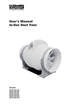
DESIGN AND OPERATING PRINCIPLE
MOUNTING AND SETUP
READ THE USER'S MANUAL BEFORE INSTALLING THE UNIT.
The fan consists of the casing 1, the electric motor attached to the inner fixing bracket 4, the cover 2 that is fixed to the casing with screws
3 (the casing spigot diameter and the cover diameter are equal to the connected air duct diameter), the terminal box 5 that incorporates
a terminal block and a capacitor and enables connection of the fan to single-phase power mains.
1 23
4
5
6
7
8
Fig. 1
6 – outer xing bracket
7 – screws
8 – bolt
The fans are designed for vertical or horizontal mounting. Air motion in the system must be in compliance with the direction of the arrow on
the fan casing. Install a hood on outlet (discharge) spigot side in case of the vertical fan installation. Provide a straight air duct section at least
1 m long on the intake spigot side in case of horizontal fan installation with maximum allowable humidity.
m
Mounting sequence:
• Remove the bolt from the casing 1 and install the fixing brackets in such a way so that the holes on the fixing brackets are aligned
with the heads of the screws 3.
• Fix the fixing brackets on the casing with bolts.
• Drill the holes in the mounting surface to match the fitment holes of the fixing brackets.
• Fix the fan with the screws.
• Connect the air ducts of the respective size to the fan and fix them with clamps.

8
VKMz
www.ventilation-system.com
CONNECTION TO POWER MAINS
ANY TAMPERING WITH THE INTERNAL CONNECTIONS IS PROHIBITED
AND WILL VOID THE WARRANTY.
DISCONNECT THE POWER SUPPLY PRIOR TO ANY OPERATIONS WITH THE UNIT.
CONNECTION OF THE UNIT TO POWER MAINS IS ALLOWED BY A QUALIFIED
ELECTRICIAN WITH A WORK PERMIT FOR THE ELECTRIC UNITS UP TO 1000 V AFTER
CAREFUL READING OF THE PRESENT USER’S MANUAL.
THE RATED ELECTRICAL PARAMETERS OF THE UNIT ARE GIVEN ON THE
MANUFACTURER’S LABEL.
The fan is designed for 230 V/50 (60) Hz single-phase alternating current mains.
The fan shall be connected to power supply by means of insulated, durable and thermal-resistant cords (cables, wires) through the
external circuit breaker with a thermal-magnetic trip built into the stationary wiring to disconnect all the power mains phases.
The rated current must be not below the rated current consumption (refer to the «Technical data» section).
The QF external switch location must ensure free access for quick shutdown of the fan.
The recommended circuit breaker nominal current is 1 A.
The recommended wire cross section is 0.75 mm
2
.
The actual conductor cross-section selection must be based on its type, the maximum permissible heating, insulation, length and
installation method (in the air, pipes or inside walls).
Connect the cables to the terminal block incorporated inside the terminal box located on the fan casing in compliance with the fan
wiring diagram and the terminal designation.
The terminal designations are shown on the sticker inside the fan casing.
Fan wiring diagram:
QF
~230 V
50 (60) Hz

9
www.ventilation-system.com
TECHNICAL MAINTENANCE
DISCONNECT THE UNIT FROM POWER SUPPLY BEFORE ANY MAINTENANCE
OPERATIONS!
ENSURE THAT THE UNIT IS SWITCHED OFF FROM THE SUPPLY MAINS BEFORE
REMOVING THE GUARD.
The technical maintenance includes periodic cleaning of the surfaces from accumulated dust and dirt.
Use a soft dry brush or a vacuum cleaner to remove dust.
The impeller blades require thorough cleaning once in 6 months.
To do this, unscrew the self-tapping screws 3 and remove the cover 2 (Fig. 1).
Clean the impeller blades with a soft cloth wetted in mild water detergent solution. Avoid liquid dripping on the motor.
POSSIBLE REASONS AND TROUBLESHOOTING
PROBLEM POSSIBLE REASONS TROUBLESHOOTING
When switching on the unit the
fan does not start.
No power supply. Check the electrical connections and the power switch status.
Motor jamming.
Turn off the fan. Troubleshoot the impeller jamming. Restart
the fan.
Circuit breaker tripping during the
fan start.
The automatic circuit breaker is
triggered by an abnormally high current
consumption due to a short circuit.
«Disconnect the fan from power mains and contact the Seller.
Do not turn on the fan again!»
Low air flow.
Clogging of air ducts or other ventilation
system elements. Impeller clogging.
Damaged air ducts. Air damper closure.
Clean the air ducts and other ventilation system elements as
well as the impeller. Check the air ducts for damage. Make sure
the air dampers and louvre shutters are open.
STORAGE AND TRANSPORTATION REGULATIONS
• Store the unit in the manufacturer’s original packaging box in a dry closed ventilated premise with temperature range
from +5 ˚С to +40 ˚С and relative humidity up to 70 %.
• Storage environment must not contain aggressive vapors and chemical mixtures provoking corrosion, insulation, and sealing
deformation.
• Use suitable hoist machinery for handling and storage operations to prevent possible damage to the unit.
• Follow the handling requirements applicable for the particular type of cargo.
• The unit can be carried in the original packaging by any mode of transport provided proper protection against precipitation and
mechanical damage. The unit must be transported only in the working position.
• Avoid sharp blows, scratches, or rough handling during loading and unloading.
• Prior to the initial power-up after transportation at low temperatures, allow the unit to warm up at operating temperature for at
least 3-4 hours.

10
VKMz
www.ventilation-system.com
MANUFACTURER’S WARRANTY
The product is in compliance with EU norms and standards on low voltage guidelines and electromagnetic compatibility. We hereby
declare that the product complies with the provisions of Electromagnetic Compatibility (EMC) Directive 2014/30/EU of the European
Parliament and of the Council, Low Voltage Directive (LVD) 2014/35/EU of the European Parliament and of the Council and CE-marking
Council Directive 93/68/EEC. This certificate is issued following test carried out on samples of the product referred to above.
The manufacturer hereby warrants normal operation of the unit for 24 months after the retail sale date provided the user's observance
of the transportation, storage, installation, and operation regulations. Should any malfunctions occur in the course of the unit operation
through the Manufacturer's fault during the guaranteed period of operation, the user is entitled to get all the faults eliminated by the
manufacturer by means of warranty repair at the factory free of charge. The warranty repair includes work specific to elimination of faults
in the unit operation to ensure its intended use by the user within the guaranteed period of operation. The faults are eliminated by means
of replacement or repair of the unit components or a specific part of such unit component.
The warranty repair does not include:
• routine technical maintenance
• unit installation/dismantling
• unit setup
To benefit from warranty repair, the user must provide the unit, the user's manual with the purchase date stamp, and the payment
paperwork certifying the purchase. The unit model must comply with the one stated in the user’s manual. Contact the Seller for warranty
service.
The manufacturer’s warranty does not apply to the following cases:
• User’s failure to submit the unit with the entire delivery package as stated in the user’s manual including submission with missing
component parts previously dismounted by the user.
• Mismatch of the unit model and the brand name with the information stated on the unit packaging and in the user's manual.
• User’s failure to ensure timely technical maintenance of the unit.
• External damage to the unit casing (excluding external modifications as required for installation) and internal components caused
by the user.
• Redesign or engineering changes to the unit.
• Replacement and use of any assemblies, parts and components not approved by the manufacturer.
• Unit misuse.
• Violation of the unit installation regulations by the user.
• Violation of the unit control regulations by the user.
• Unit connection to power mains with a voltage different from the one stated in the user's manual.
• Unit breakdown due to voltage surges in power mains.
• Discretionary repair of the unit by the user.
• Unit repair by any persons without the manufacturer’s authorization.
• Expiration of the unit warranty period.
• Violation of the unit transportation regulations by the user.
• Violation of the unit storage regulations by the user.
• Wrongful actions against the unit committed by third parties.
• Unit breakdown due to circumstances of insuperable force (fire, flood, earthquake, war, hostilities of any kind, blockades).
• Missing seals if provided by the user’s manual.
• Failure to submit the user’s manual with the unit purchase date stamp.
• Missing payment paperwork certifying the unit purchase.
FOLLOWING THE REGULATIONS STIPULATED HEREIN WILL ENSURE A LONG AND
TROUBLEFREE OPERATION OF THE UNIT.
USER’S WARRANTY CLAIMS SHALL BE SUBJECT TO REVIEW ONLY UPON
PRESENTATION OF THE UNIT, THE PAYMENT DOCUMENT AND THE USER’S MANUAL
WITH THE PURCHASE DATE STAMP.

11
www.ventilation-system.com
CERTIFICATE OF ACCEPTANCE
Unit Type Centrifugal inline fan
Model VKMz____
Serial Number
Manufacture Date
Quality Inspector’s
Stamp
SELLER INFORMATION
Seller
Seller’s Stamp
Address
Phone Number
E-mail
Purchase Date
This is to certify acceptance of the complete unit delivery with the user’s manual. The warranty terms are
acknowledged and accepted.
Customer’s Signature
INSTALLATION CERTIFICATE
The VKMz____ unit is installed pursuant to the requirements stated in the present user's manual.
Installation Stamp
Company name
Address
Phone Number
Installation
Technician’s Full Name
Installation Date: Signature:
The unit has been installed in accordance with the provisions of all the applicable local and national construction,
electrical and technical codes and standards. The unit operates normally as intended by the manufacturer.
Signature:
WARRANTY CARD
Unit Type Centrifugal inline fan
Seller’s Stamp
Model VKMz____
Serial Number
Manufacture Date
Purchase Date
Warranty Period
Seller

V05-1EN-11
/