
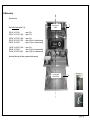
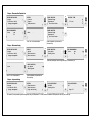
system documentation quattro GB V13.docx / Page 1
Safety lighting - System documentation
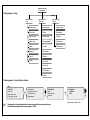
Installation Page 11-18
Description, operating notes, data Page 19-24
Principle circuit diagrams Page 25-33
Commissioning Page 34-35
Operating instructions Page 36-53
Manufacturer notes Page 54
Appendix 1 – Possible fault indications of the system Page 55
Appendix 2 – Factory acceptance report / Test Report Page 57/58
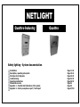
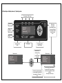
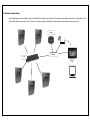
NETLIGHT
Quattro
-
Industry
Quattro

system documentation quattro GB V13.docx / Page 2

system documentation quattro GB V13.docx / Page 3

system documentation quattro GB V13.docx / Page 4

system documentation quattro GB V13.docx / Page 5
Content
1. IMPORTANT INFORMATION 7
1.1 NOTES FOR QUALIFIED PERSONNEL 7
1.2 SAFETY INSTRUCTIONS 7
1.3 EXPLANATION OF SYMBOLS 8
1.4 INTENDED USE 8
1.5 CONFIGURATION 8
1.6 VDE INSTRUCTIONS FOR THE NETLIGHT SYSTEM (VDE 0711-400 / EN 62034) 9
2. SYSTEM DELIVERY, STORAGE 10
2.1 PACKAGING INSPECTION 10
2.2 DAMAGE COMPLAINT 10
2.3 STORAGE / BATTERY STORAGE PERIOD 10
2.4 UPRIGHT TRANSPORT 10
2.5 PACKAGING DISPOSAL/PACKAGING 10
3. INSTALLATION 11
3.1 INSTRUCTIONS 11
3.2 INSTALLATION PREPARATION 11
3.3 OPENING/CLOSING THE DEVICE 12
3.4 WALL MOUNTING 13
3.5 EXPANSION HOUSING 14
3.6 CABLE ENTRY/FUSES 15
3.7 CONNECTION COMPARTMENT 16
3.8 BATTERY CONNECTION COMPARTMENT 17
3.9 BATTERY INSTALLATION 18
3.10 INSTALLATION COMPLETION TASKS 18
4. DESCRIPTION, OPERATING NOTES AND TECHNICAL DATA 19
4.1 QUATTRO OVERVIEW 19
4.2 QUATTRO-INDUSTRY OVERVIEW 20
4.3 OPERATING AND DISPLAY ELEMENT / OPERATING NOTES 21
4.4 PRODUCT DESCRIPTION 22
4.5 TECHNICAL DATA 23
4.6 NAVIGATION KEYPAD / OPERATING NOTES 24
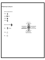
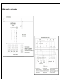
5. PRINCIPLE CIRCUIT DIAGRAMS, TERMINAL DIAGRAM 25
5.1.1 CIRCUIT DIAGRAM – 230V, FINAL CIRCUITS 1-4, INPUTS 1-4, LAN, USB 25

system documentation quattro GB V13.docx / Page 6
5.1.2 CIRCUIT DIAGRAM – MESSAGES, INPUTS E5-9, PANEL , MODULE BUS 26
5.2.1 TERMINAL DIAGRAM -X2, -X4, -X5 27
5.2.2 TERMINAL DIAGRAM -X6, -X8, -X9 28
5.3 MAINS CONNECTION + PANEL CONNECTION 29
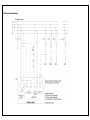
5.4 THREE-PHASE MONITORING 30
5.5 DIGITAL INPUTS 1-4 / 230V AC 31
5.6 NETWORK MONITORING LOOP / DIGITAL INPUTS 5-8 FOR POT. FREE CONTACTS 32
5.7 EXAMPLE OF NETWORK WIRING 33
6. COMMISSIONING 34
6.1 CHECKS BEFORE COMMISSIONING 34
6.2 COMMISSIONING 34
6.2.1 NOTES ON VOLTAGE MEASUREMENTS 34
6.2.2 CONNECTION OF THE MAINS SUPPLY LINE 34
6.2.3 CONNECTING THE MAINS SUPPLY AND MONITORING THE SYSTEM STARTUP 34
6.2.4 SWITCHING ON THE BATTERY 34
6.2.5 MONITORING OF BATTERY VOLTAGE AND CHARGING CURRENT ON THE MASTER DISPLAY 34
6.3 DISCONNECTING THE SYSTEM FROM THE POWER SUPPLY 35
7. OPERATION OF THE OPERATING AND DISPLAY ELEMENT 36
7.1 MENU OVERVIEW 36
8. MANUFACTURER NOTES 54
8.1 REPLACING THE BATTERY TO SECURE THE TIMER FUNCTION 54
APPENDIX 1 – POSSIBLE FAULT INDICATIONS OF THE SYSTEM 55
APPENDIX 2 - FACTORY ACCEPTANCE REPORT 57

system documentation quattro GB V13.docx / Page 7
1. Important information
1.1 Notes for qualified personnel
Attention! Risk of injury or death
Only authorised and trained persons, who take all safety regulations into consideration, may carry out work on the equipment. Wrong or faulty installation may result in personal
injury and/or property damage.
- Cable lengths must be taken into account and must not be exceeded.
- Protection type and class must be designed according to the local conditions.
- Ventilation or cooling of the systems and their components must be ensured.
- The environment and work area must be set up in accordance with occupational health and safety regulations or comply with local safety regulations.
- E30 enclosures must be adapted to local conditions and installed horizontally. Particular attention must be paid to the fire resistance duration,
compliance with the specimen guidelines according to MLAR 11/2005 and EltBauVO 01/2009.
The depicted views/illustrations shown in this manual may differ from the delivery status. Special or customer-specific versions are listed/described as attachments in the appendix of
this manual.
Guidelines/standards
The installation may generally only be carried out in accordance with the relevant guidelines and standards of electrical engineering, for this purpose the national regulations and
guidelines of the installation location/country must be observed.
Only luminaires with electronic ballasts that correspond to the respective operating voltages specified in the data sheet may be used on the final circuits of the
system. The nominal operating voltage of the system is 230V/50Hz. The use of conventional ballasts will destroy the circuit electronics!
These operating and assembly instructions do not contain all detailed information on all types of the product series and cannot take into account every application of the products. All
information is for the sole purpose of describing the product and is not to be understood as warranted characteristics in the legal sense. Further information and data can be obtained
from your supplier or directly from the manufacturer.
1.2 Safety instructions
Working on the system
For safety reasons, the system must be disconnected when working on it. (When working on electrical systems, the five safety rules must be observed)
Important note: In systems with battery voltage, switching off the mains supply triggers automatic switching to the battery voltage! The battery may only be disconnected or
switched off when it is not under load (risk of arcing). To do so, follow the sequence in point 6.3.
Attention! Risk of injury or death
Generally speaking, there is an increased risk of injury or death when working on batteries or with battery voltages, so it is essential to ensure correct operation. Please read the
information provided by the battery manufacturer and the instructions of the battery mounting personnel.
The Netlight quattro works internally with 24V DC! (charger, battery, inverter)

system documentation quattro GB V13.docx / Page 8
F
1.3 Explanation of symbols
The following symbols indicate technically important safety instructions in this manual. These must be observed since they relate to occupational safety.
Attention! Risk of injury or death
This symbol is used to identify information which, if ignored, may result in injury, health problems or even death.
Caution!
This symbol is used to identify information which, if ignored, may result in system failure or even material damage.
Notes
This symbol provides important information for working with the system or parts of it.
1.4 Intended use
The central power supply system is only suitable for use in safety lighting systems. It is used to monitor and control the safety lighting system with general lighting and emergency
lighting. The system is equipped with an automatic testing device. Intended use can only be guaranteed if the setting / programming is carried out exclusively by trained specialist
personnel with all the necessary knowledge for safety lighting systems.
1.5 Configuration
Please note that the Quattro is configured via the USB interface, see page 50.
Do not remove the SD card, as it contains the operating system of the system. Changes to the SD card can or will lead to system failure;
only the manufacturer or authorised service personnel may make changes.
!
!

system documentation quattro GB V13.docx / Page 9
F
1.6 VDE instructions for the Netlight system (VDE 0711-400 / EN 62034)
- For the functional test in accordance with EN 62034 3.6, a light test must be carried out in the Netlight system and then a device test.
- The Netlight-quattro control unit with integrated ATS (Automatic Test System) can be used in accordance with EN62034 4.1 for emergency lighting of type ER /PER.
- The maximum system size of Netlight-quattro depends on the setting of the address mode of 99 devices in a module bus in Netlight system. Alternatively up to 32x systems can be
operated via the visualization software on an Ethernet network. 4 circuits (max. 80 luminaires) per system
- In accordance with EN 62034 4.1, we point out that no LB1/LÜ1 luminaire modules can be used in Netlight quattro!
Current modulating electronic ballasts can be used in systems with MSÜ luminaire modules.
- The timing circuit (EN 62034 4.2) is a component of the Netlight-quattro control unit's firmware. In case of processor crash the system program is reset by a Watch_Dog_IC, which
ensures immediate and correct continuation. The switching times are stored in the non-volatile memory.
(Refer to the information in this instruction manual for service under point 8.1)
- During the Netlight-quattro functional test, even a longer one, only approx. 1% of the battery of the Netlight system is used up; this value is far below the 10% required according
to EN 62034 5.1, so that it is not necessary to defer a test after power failure. Test operations are blocked in case of battery undervoltage and emergency operation.
- The automatic test of the total measurement duration of the system required under EN 62034 5.2 is not available for the Netlight system, as it cannot be estimated whether an
event or other activities requiring the operational readiness of the Netlight system will be carried out at this point in time. Instead, the Netlight system provides a fault message
(programmable date) which is activated after a 1-year period (with repeat function) and can only be deactivated by a service technician.
- The Netlight ATS ensures the battery of the Netlight system is hardly used up for testing purposes.
- Netlight timers are operated by quartz-controlled clock circuits and therefore exhibit quartz accuracy.
- The time control function is secured in the Netlight-quattro itself by means of a backup battery, which must be replaced every 5 years as a precaution, see section 8.1.
- The limited endurance test EN 62034 6.3.3.4 is started manually in Netlight-quattro with an endurance test (see section 7.7) and is then terminated after 2/3 of the time by pressing
the OK key. Such a termination is not considered an error by the system, but is documented in the test report with date, time and battery data (U/I).
- All defect reports from test operations cannot be deleted by actions, but only by successfully passing the next test. This also applies to luminaire faults. Even if the endurance test is
interrupted due to a power failure or deep discharge, the error message is still shown on the display; only a successful new test deletes the error message.

system documentation quattro GB V13.docx / Page 10
2. System delivery, storage
2.1 Packaging inspection
Upon receipt the goods must be checked to ensure they are intact and complete. If the packaging is damaged, it must immediately be opened. Missing items or damages must
immediately be reported, otherwise all claims against the transport company will lapse. See delivery note for address.
2.2 Damage complaint
Immediately after receipt, check the delivery for completeness and transport damage. Do not accept or accept only under reserve deliveries with visible external transport damage.
2.3 Storage / Battery storage period
The device must not be exposed to building rubble or dusty dirt. The room must be clean and dry. The ambient temperature may vary within a range of -5 to 40°C at most. Condensation
must be excluded.
If batteries are supplied with the system, they must also be stored in a clean, dry place. The ambient temperature should be between 0 and 25°C. It must be ensured that the batteries
are charged after 6 months at the latest or when the open-circuit voltage drops below 2.08V/Z.
The warranty expires in case of improper or too long storage.
2.4 Upright transport
The systems/devices/distributors should always be transported in an upright position unless otherwise described on the packaging. Use only suitable accessories for transport and make
sure no one is at risk.
2.5 Packaging disposal/packaging
Packaging should be separated according to type and size of materials.
Environmentally sound disposal should be considered a matter of course.
A recycling company will be happy to help you with professional disposal.
National guidelines and regulations for batteries and electronic components must also be observed.

system documentation quattro GB V13.docx / Page 11
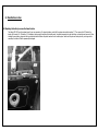
3. Installation
3.1 Instructions
The system may only be transported, set up, connected, commissioned, serviced and operated by specialists who are familiar with the currently valid safety and installation regulations.
Prior to installation and initial commissioning of the system, the present operating instructions must be read carefully by the personnel who work with or on the system. Some of the
diagrams and illustrations contained in these assembly/operating instructions are only intended to illustrate the constellations shown. Illustrations and circuit diagrams must always be
adhered to when it comes to special features on site for specially designed emergency lighting systems.
These instructions were compiled in compliance with the applicable regulations and state of the art. All relevant documents must be made available accordingly to persons working on
the system.
Should other standards or regulations apply, the respective supplier assumes liability or warranty for any damage/defects resulting therefrom, for his supplied or installed safety lighting
systems. In the respective countries in which the systems are operated, all directives, laws and standards should also be taken into account.
Spare parts
Incorrect or defective spare parts can lead to malfunctions, damage or failure. That is why only original parts or spare parts approved by the manufacturer may be used. Claims for
damages/service/liability/warranty shall lapse in the event of infringement.
Warnings
Installations or systems such as those described in the manual may only be used in a technically faultless condition and only for the intended purpose. The safety instructions in the
manual as well as the operator's instructions must be observed. For the safe operation of the installation or system, it is essential to comply with the information in the data sheet.
Failure to observe this information may cause damage to the installation or system and, in the worst case, failure or injury.
Any safety-relevant defects or malfunctions of the installation or system must be reported immediately to the person responsible for the installation or system.
3.2 Installation preparation
Electrical systems must be disconnected before starting work on them. If a safety emergency lighting system is already in place, make sure that the system (battery system) switches
to battery backup power supply after having been disconnected. The existing system must then be switched off and dismantled in accordance with the manufacturer's instructions.
Consumers, luminaires and ballasts only function properly if they are suitable for the operating voltage of 230V 50Hz. In emergency operation, the battery power supply supplies the
consumers with 230V 50Hz via an inverter. The battery power supply must be connected to the correct pole, wrong pole direction can damage the system and in the worst case cause
personal injury.
As a general rule, it should be noted here again that improper handling of electrical systems, whether with battery backup power supply or with other emergency power supply, may
result in injury or death due to electric arcs, high currents or sudden discharges.
Check whether the installation site (wall) is horizontal/flat and has sufficient load-bearing capacity for the system. Remove covers (keep them safe from damage) and fasten/clip on
any components that have been loosened during transport.
!
!

system documentation quattro GB V13.docx / Page 12
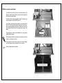
3.3 Opening/closing the device
After closing replace
the screws.
Observe the safety instructions
under section 1.2!
Inside view
Dome pins for fixing the
housing cover; when closing,
make sure that the pins are
seated correctly in their
uptakes.
When closing the hood, first
place it at an angle with the
upper dome pins and then
fold it down
Rem
ove screws
On both sides of the hood
lift the side walls from the
rear and from below
After lifting fold
up to the front,
vice versa when closing

system documentation quattro GB V13.docx / Page 13
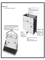
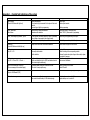
3.4 Wall mounting
Dimensions in mm
Weight without battery approx. 14 kg
250VA 1h / 2x 12V 18Ah – approx. 25 kg
350VA 1h / 4x 12V 18Ah (36Ah) – approx. 35 kg
225VA 3h / 4x 12V 18Ah (36Ah) – approx. 35 kg
250VA 3h / 4x 12V 26Ah (52Ah) – approx. 48 kg incl. 1x expansion housing
350VA 3h / 2x 12V 65Ah – approx. 61 kg incl. 1x expansion housing
88VA 8h / 4x 12V 18Ah (36Ah) – approx. 35 kg
188VA 8h / 2x 12V 65Ah – approx. 61 kg incl. 1x expansion housing
250VA 8h / 4x 12V 65Ah (90Ah) – approx. 109 kg incl. 3x expansion housing
Remove the battery from the battery compartment before mounting.
0
19
550
Dist. hole centre
359mm
Dist. hole centre
300mm (Ø 7mm)
12mm
Ø 7mm
14mm
Rear panel
construction

system documentation quattro GB V13.docx / Page 14
3.5 Expansion housing
Extra battery compartment for additional batteries.
Open (2):
Next, push the
housing outwards
from the bottom, left
and right.
Close:
The inverted order of "open"
Open (3):
Finally, pull the
housing away from
the front and down.
Open (1):
The quattro housing must be open, then
remove the screw at the top (bottom of the
quattro housing).
Insert these three lugs underneath the quattro housing or
the expansion housing above it and fasten it to the wall
using the four holes in the rear panel.

system documentation quattro GB V13.docx / Page 15
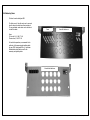
3.6 Cable entry/fuses
15x holes for metric cable gland M20
The black cover of the cable entry can be removed
from the frame if no cables have been inserted yet.
The pre-perforated round entries can be broken out
to insert the cables.
Fuses:
F1-4 circuits 1-4 / 6.3x32 T 1.6A
F5 mains fuse / 6.3x32 T 6.3A
For trouble-free operation, we recommend for the
cable entry of the measuring and signalling cables
the use of EMC cable glands M20 e. g. from Kaiser.
Shielded cables should also be used for the
measuring and signalling cables.
View without black cover
View
with black cover
Fuses

system documentation quattro GB V13.docx / Page 16
3.7 Connection compartment
Terminal cross section –X2, X4, X6 to X9:
0.08-1.5mm² single-wire/fine-stranded wire,
0.25-1.5mm² fine-stranded with ferrule
with/without plastic collar.
Stripping length 5-6mm
Terminal cross section –X5
0.5-1.5mm² single-wire/fine-stranded wire,
0.5-1.5mm² fine-stranded with ferrule
with/without plastic collar.
Stripping length 7.5-8.5mm
Signalling relay contacts:
Switching capacity - 1250VA/AC | 150W/DC
Switching voltage - max. 125V/DC | 250V/AC
Switching current - max. 5 A
Nominal load:
250 V/AC | 5 A
30 V/DC | 5 A
-X8 terminals for 4x final circuits L/N/PE
Colour grey/ blue/ light green
230V 50Hz from mains or inverter.
per circuit - fuse protection 6.3x32 T1.6A
per circuit max. 200VA
Total power of circuits 1 to 4 max. 350VA
-X2 / signalling terminals
There are 3x messages: fault,
battery operation and ready for
operation.
-X5 power supply SV/24V for
panel (see 5.3)
Connection compartment
Signalling terminals
-X9 grey/ blue/ light
green terminals for
mains connection
L/N/PE 230V 50Hz
1-phase
Mains fuse
6.3x32 T 6.3A
-X4: Module BUS
-X5: 1- 2 Mains monitor connection with loop monitoring
-X5: 3-10 Digital inputs for pot. free contacts
-X5: 11-14 24V OUT (panel supply)
For connection see chapter 5
-X6 - 4x Digital inputs
230V AC for switching or
local emergency operation or
three-phase network monitor
(s. chap. 5)
Mains
Final circuits
Digital inputs

system documentation quattro GB V13.docx / Page 17
F
3.8 Battery connection compartment
Use batteries only with AMP 6.3 plug, the connection cables for the
battery are included in the unit, battery connectors are only supplied for
deliveries which include batteries.
The battery cables are laid or designed to be earth- and short-circuit-
proof in accordance with DIN VDE 0100 Part 520.
For the battery, please observe the regulations in accordance with DIN
VDE 0510 Part 2 and read the battery manufacturer's data sheets.
Before connecting the battery, make sure to compare the set values for
trickle charge and boost charge of the charger with the values of the
battery.
Legal regulations that exist at the installation site for safety lighting
systems must be observed.
When connecting the battery, pay attention to the polarity, the red wire
is plus (+), the black wire is minus (-).
Please note that incorrect polarity, short-circuit or incorrect handling
may result in personal injury or damage to the unit or battery.
Observe the commissioning instructions!
Example / Sample batteries
Red (plus)
Black
(minus)

system documentation quattro GB V13.docx / Page 18
3.9 Battery installation
(Examples based on the SBL battery series)
3.10 Installation completion tasks
- Make sure that the system is free of dust and that no tools are left behind after installation. Loose parts and tools lying around are sources of danger!
- Make sure that the covers are fitted correctly (can only be installed after commissioning)

system documentation quattro GB V13.docx / Page 19
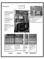
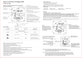
4. Description, operating notes and technical data
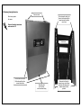
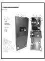
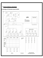
4.1 Quattro overview
Housing dimensions:
H – 605mm
W – 410mm
D – 205mm
without cable glands
without expansion housing
Expansion housing:
H – 250mm
W – 410mm
D – 205mm
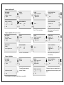
1. Fuses
2. Cable entry
3. USB/network connection
4. Fixing holes (keyhole 12/7 mm)
5. Connection compartment
6. Base board
7. Display and control panel
8. Charging unit (picture shows option with 2nd charging unit)
9. Inverter
10. Mounting holes (7mm hole)
11. Battery compartment for max. 4x 12V 17-18Ah
12. Housing hood
13. Housing frame
7
1
2
3
12
7
1
3
5
4
2
4
6
8
9
11
10
13
10

system documentation quattro GB V13.docx / Page 20
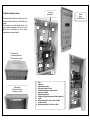
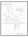
4.2 Quattro-Industry overview
The Quattro-Industry differs from the Quattro only in its
housing and that the variant type 7 with 4x 65Ah is not
possible.
The advantage of the Quattro-Industry version is the
larger connection compartment, the door can only be
opened with a corresponding key and 2x battery
compartments are already integrated.
Cable entry via
membrane gland plate
Wall mounting
Distance hole-7mm to
top edge of roof 30mm
Hole centre 359mm
HxWxD
approx.
1000x500x250mm
1. Fuses
2. Cable entry
3. USB/network connection
4. Fixing holes (keyhole 12/7 mm)
5. Connection compartment / Mains connection
6. Base board / Terminals
7. Display and control panel
8. Charging unit (figure shows option with 2nd charging unit)
9. Inverter
10. Battery compartment 1 for max. 4x 12V 17-18Ah or
2x 26Ah or 1x 65Ah
11. Battery compartment 2 for 2x 26Ah or 1x 65Ah
11
10
2
4
4
5
1
3
6
7
9
8
Terminals
See chapter 3.7
10
Page is loading ...
Page is loading ...
Page is loading ...
Page is loading ...
Page is loading ...
Page is loading ...
Page is loading ...
Page is loading ...
Page is loading ...
Page is loading ...
Page is loading ...
Page is loading ...
Page is loading ...
Page is loading ...
Page is loading ...
Page is loading ...
Page is loading ...
Page is loading ...
Page is loading ...
Page is loading ...
Page is loading ...
Page is loading ...
Page is loading ...
Page is loading ...
Page is loading ...
Page is loading ...
Page is loading ...
Page is loading ...
Page is loading ...
Page is loading ...
Page is loading ...
Page is loading ...
Page is loading ...
Page is loading ...
Page is loading ...
Page is loading ...
Page is loading ...
Page is loading ...
-
 1
1
-
 2
2
-
 3
3
-
 4
4
-
 5
5
-
 6
6
-
 7
7
-
 8
8
-
 9
9
-
 10
10
-
 11
11
-
 12
12
-
 13
13
-
 14
14
-
 15
15
-
 16
16
-
 17
17
-
 18
18
-
 19
19
-
 20
20
-
 21
21
-
 22
22
-
 23
23
-
 24
24
-
 25
25
-
 26
26
-
 27
27
-
 28
28
-
 29
29
-
 30
30
-
 31
31
-
 32
32
-
 33
33
-
 34
34
-
 35
35
-
 36
36
-
 37
37
-
 38
38
-
 39
39
-
 40
40
-
 41
41
-
 42
42
-
 43
43
-
 44
44
-
 45
45
-
 46
46
-
 47
47
-
 48
48
-
 49
49
-
 50
50
-
 51
51
-
 52
52
-
 53
53
-
 54
54
-
 55
55
-
 56
56
-
 57
57
-
 58
58


GFS NETLIGHT Quattro-Industry User manual
- Type
- User manual
- This manual is also suitable for
Ask a question and I''ll find the answer in the document
Finding information in a document is now easier with AI
Other documents
-
M-Cab 7001121 Datasheet
-
 Deegotech 43237-2 User manual
-
 T'nB PINB180U Datasheet
-
Land Rover TESTBOOK Owner's manual
-
 Sargent Supercharge 201 User Instructions
-
ClearSounds QUATTRO 4.0 LITE Owner's manual
-
Chacon 56041 User manual
-
 NAMRON 1402768 LED Dimmer TW ZigBee 250W User manual
-
Conrad Components 193640 TDR Component 24 V DC 1 - 40 s Operating instructions
-


