
INSTRUCTION MANUAL
GAS FRYERS
ELECTRIC FRYERS
SERIES 70
286917 2859251
286925 2859171
286922 2859271
INSTALLATION, USE
AND MAINTENANCE
GB/UK

Pag. 2/63
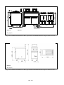
2859171 2859271
(G= gas\gaz)
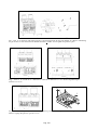
Fig. – Abb. 1:
Dimensioni \ Dimensions \ Floor space dimensions \ Raumbedarfsmasse \ Espacio máximo necesario
2859251
(G= gas\gaz)
Fig. – Abb. 2: Dimensioni \ Dimensions \ Floor space dimensions \ Raumbedarfsmasse \ Espacio máximo necesario

Pag. 3/63
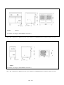
286925 286917
(E= elettrico \ électrique \ electric\ Elektrisch \
eléctrico)
Fig. – Abb. 3: Dimensioni \ Dimensions \ Floor space dimensions \ Raumbedarfsmasse \ Espacio máximo necesario
286922
(E= elettrico \ électrique \ electric\ Elektrisch \
eléctrico)
Fig. – Abb. 4: Dimensioni \ Dimensions \ Floor space dimensions \ Raumbedarfsmasse \ Espacio máximo necesario

Pag. 4/63
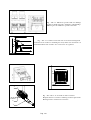
Fig. – Abb. 5: targhetta caratteristiche \ Plaques des caractéristiques \ data plate\ typenschild \ Chapa características
E
G
100
100
Fig. – Abb. 6: installazione \ Lieu d'installation \ Place \ Installationsort \ Lugar
CAT/KAT
GAS/GAZ
G30 G31 G20
G25 G25.1
G110 G120
Made in E.U.
I
2H
p mbar - - 20 - - - -
LV
I
3P
p mbar - 37 - - - - -
IS
I
3B/P
p mbar
28-30
28-30
- - - - -
CY MT
II
2E+3P
p mbar - 37 20 25 - - -
LU
II
2E+3+
p mbar
28-30
37 20 25 - - -
FR BE
XXXX
II
2H3+
p mbar 30 37 20 - - - -
IT PT GR GB
Nr.
II
2H3+
p mbar 28 37 20 - - - -
ES IE CH
TIPO/TYPE
A
II
2E3P
p mbar - 37 20 - - - -
PL
MOD.
II
2ELL3B/P
p mbar 50 50 20 20 - - -
DE
ART.
II
2H3B/P
p mbar 50 50 20 - - - -
AT CH CZ SK
N°.
II
2H3B/P
p mbar
28-30
28-30
20 - - - -
FI LT BG
kW B
II
2H3B/P
p mbar
28-30
28-30
20 - - - -
NO SK RO
Σ
ΣΣ
ΣQn
m³/h C
II
2H3B/P
p mbar
28-30
28-30
20 - - - -
EE SI HR TR
kg/h D
II
2HS3B/P
p mbar
28-30
28-30
25 - 25 - -
HU
II
2L3B/P
p mbar 30 30 - 25 - - -
NL
kW
E
V ~
F III
1ab2H3B/P
p mbar
28-30
28-30
20 - - 8 8
SE
Hz
G
III
1a2H3B/P
p mbar
28-30
28-30
20 - - 8 -
DK
Predisposto a gas-Prévu pour gaz-Voreinstellung für Gas-Predisposto a gás-Voorzien van gas-Set for use with gas-Preparado para gas-
Ment for å brukes med gass-Avsett för att användas med gas-Tarkoitettu käytettäväksi kaasulla-Forberedt til brug af
gas- - Zaízení na plyn - Toimib gaasi põhjal - A berendezés gáz használatára
elõkészített – Sagatavota darbam ar gz – Przysposobione na gas – Numatyta dumjos - Nastavený na plyn –
Pripravljeno za plin
G20 20mbar (H)

Pag. 5/63
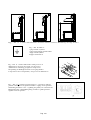
Figg. – Abb. 7, 8, 9 : Scarico fumi \ Évacuation des fumées \ Fumes evacuation \ Rauchabzug \ Descarga de humos
Fig. – Abb. 10: Simbolo
equipotenziale \ Symbole
equipotenziel \ Equipotenziale label \
Äquipotenzial Symbol \
Equipotencial símbolo
Fig. – Abb. 11: Verifica della tenuta e della pressione di
alimentazione \ Contrôle de la tenue et de la pression
d'alimentation \ Checking gas tightness and pressure \
Überprüfung der Dichtigkeit und des Versorgungsdrucks \
Comprobación de la estanqueidad y de la presión de alimentación
Fig.. – Abb. 12:
Sostituzione ugello bruciatore – regolazione dell’aria
primaria \ Changement du gicleur du brûleur - réglage de l'air primaire \
Substituting the burner nozze - regulating the primary air \ Austausch der
Hauptbrennerdüse - Primärluftregelung \ Cambio boquilla quemador -
regulación del aire primario.

Pag. 6/63
Fig. – Abb. 13: Sostituzione dell’ugello bruciatore pilota\ Changement du gicleur du brûleur de veilleuse\ Substituting
the pilot burner nozzle\ Austausch der Zündbrennerdüse \
Cambio de la boquilla del quemador piloto
Figg. – Abb. 14, 15 : Istruzioni uso \ Instructions d’utilisation \ Instruction for use \ Bedienungsanleitungen \
Instrucciones de uso
Fig. – Abb. 16, 17 : Preparazione alla cottura \ Préparation pour la caisson \ Preparation for cooking \ Vorbereitung des
Frittiervorgangs \ Preparación para la cocción

Pag. 7/63
Fig. – Abb. 18 : Filtrazione periodica dell’olio \ Filtrage
régulier de l'huile \ Periodic oil filtration \ Regelmäßige
Filterung des Öls \ Filtración periódica del aceite
Fig. – Abb. 19: Sostituzione del termostato di sicurezza \ Changement
du thermostat de sécutité \ Sobstituting the safety thermostat \ Austausch von
Sicherheits Thermostat \ Cambio de los termostado de seguridad
Fig. – Abb. 20, 21, 22: Sostituzione delle resistenze \
Remplacement des rèsistances \ Heating element replacement \
Heizungenersatz \ Sustituciòn resistencias

Pag. 8/63
Abb. 23 : Istruzioni uso \ Instructions d’utilisation \ Instruction
for use \ Bedienungsanleitungen \ Instrucciones de uso

Pag. 36/63
(
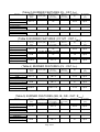
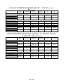
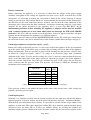
Table 1) TECHNICAL FEATURES (GB-IE-LU-NO-GR-FI-NL-SE-DK)
Model Description
Dimensions
LxDxH [mm]
Power.
Gas (B)
[kW]
Type
(A)
LPG
Consumptio
n (G30) (D)
[Kg/h]
METHANE
Consumptio
n (G20) (C)
[m3/h]
Air for
comb.
[m3/h]
Gas connector
Elect.
Power
(E)
[kW]
Tension
(F)
[V]
Freq.
(G)
[Hz]
Cable Type
H07 RN-F
[2 mm]
Vat Oil Load
[l]
Maximum Vat
Load
[kg]
Maximum Hour
Production
[kg/h]
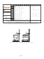
2859171 Gas fryer ½ unit 400x700x850
15
A 1/
B11
1.182 1.544 30
UNI-ISO 7/1 R ½
- - - - 23 2 20
2859251 Gas fryer ½ unit 400x700x850
11 A1 0,867 1,164 22
UNI-ISO 7/1 R ½
- - - - 7+7 1 + 1 18
2859271 Gas fryer 1 unit 800x700x850
30
A 1/
B11
2.365 3.089 60
UNI-ISO 7/1 R ½
- - - - 23 + 23 2 + 2 40
286917 Electric fryer ½ unit 400x700x850
- - - - - - 15 400 – 3+N 50 5 x 4 23 2 22
286922 Electric fryer 1 unit 800x700x850
- - - - - - 30 400 – 3+N 50 5 x 10 23 + 23 2 + 2 44
286925 Electric fryer ½ unit 400x700x850
- - - - - - 15 400 – 3+N 50 5 x 4 9+9 1,25 + 1,25 25

Pag. 37/63
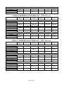
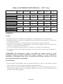
(Table 2) BURNER FEATURES (IS - CAT. I
3P
)
Gas type Nominal
capacity
[kW]
Reduced
capacity [kW]
Diameter of main
injectors
[1/100 mm]
By-Pass
diameter
[1/100 mm]
Pilot injectors
[N°]
Air regulation
“x”
[mm]
FRYER BURNER ½ module (7 liter)
Liquid Gas PLG
(G31)
5,5 x 2 - 115 - 30 x 2 Open
FRYER BURNER ½ module
Liquid Gas PLG
(G31)
15.00 - 115 - 30 Open
FRYER BURNER 1 module
Liquid Gas PLG
(G31)
15.00x 2 - 115 x 2 - 30 x 2 Open
(Table 3) BURNER FEATURES (CY, MT - CAT. I
3B/P
)
Gas type Nominal
capacity
[kW]
Reduced
capacity [kW]
Diameter of main
injectors
[1/100 mm]
By-Pass
diameter
[1/100 mm]
Pilot injectors
[N°]
Air regulation
“x”
[mm]
FRYER BURNER ½ module (7 liter)
Liquid Gas PLG
(G30-G31)
5,5 x 2 - 115 - 30 x 2 Open
FRYER BURNER ½ module
Liquid Gas PLG
(G30-G31)
15.00 - 115 - 30 Open
FRYER BURNER 1 module
Liquid Gas PLG
(G30-G31)
15.00x 2 - 115 x 2 - 30 x 2 Open
(Table 4) BURNER FEATURES (LV - CAT. I
2H
)
Gas type Nominal
capacity
[kW]
Reduced
capacity [kW]
Diameter of main
injectors
[1/100 mm]
By-Pass
diameter
[1/100 mm]
Pilot injectors
[N°]
Air regulation
“x”
[mm]
FRYER BURNER ½ module (7 liter)
Natural Methane gas
(G20)
5,5 x 2 - 170 x 2 - 51 x 2 Open
FRYER BURNER ½ module
Natural Methane gas
(G20)
14.60 - 170 x 3 - 51 Open
FRYER BURNER 1 module
Natural Methane gas
(G20)
14.60x 2 - 170 x 3 x 2 - 51 x 2 Open
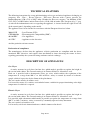
(Table 5) BURNER FEATURES (GB, IE, GR - CAT. II
2H3+
)
Gas type Nominal
capacity
[kW]
Reduced
capacity [kW]
Diameter of main
injectors
[1/100 mm]
By-Pass
diameter
[1/100 mm]
Pilot injectors
[N°]
Air regulation
“x”
[mm]
FRYER BURNER ½ module (7 liter)
Liquid gas LPG
(G30-G31)
5,5 x2 - 115 x 2 - 30 x 2 Open
Natural Methane gas
(G20)
5,5 x 2 - 170 x 2 - 51 x 2 Open
FRYER BURNER ½ module
Liquid gas LPG
(G30-G31)
15.00 - 115 x 3 - 30 Open
Natural Methane gas
(G20)
14.60 - 170 x 3 - 51 Open

Pag. 38/63
FRYER BURNER 1 module
Liquid gas LPG
(G30-G31)
15.00 x 2 - 115 x 3 x 2 - 30 x 2 Open
Natural Methane gas
(G20)
14.60 x 2 - 170 x 3 x 2 - 51 x 2 Open
(Table 6) BURNER FEATURES (NL - CAT. II
2L3B/P
)
(Table 7) BURNER FEATURES (HU - CAT. II
2HS3B/P
)
Gas type Nominal
capacity
[kW]
Reduced
capacity [kW]
Diameter of main
injectors
[1/100 mm]
By-Pass
diameter
[1/100 mm]
Pilot injectors
[N°]
Air regulation
“x”
[mm]
FRYER BURNER ½ module (7 liter)
Liquid gas LPG
(G30-G31)
5,5 x 2 - 115 x 2 - 30 x 2 Open
Natural Methane gas
(G20)
5,5 x 2 - 160 x 2 - 51 x 2 Open
Natural Methane gas
(G25.1)
5,5 x 2 - 185 x 2 - 51 x 2 Open
FRY TOP BURNER 1/2 module
Liquid gas LPG
(G30-G31)
15.00 - 115 x 3 - 30 Open
Natural Methane gas
(G20)
14,60 - 160 x 3 - 51 Open
Natural Methane gas
(G25.1)
14,60 - 185 x 3 - 51 Open
FRY TOP BURNER 1 module
Liquid gas LPG
(G30-G31)
15.00 x 2 - 115 x 3 x 2 - 30 x 2 Open
Natural Methane gas
(G20)
14,60 x 2 - 160 x 3 x 2 - 51 x 2 Open
Natural Methane gas
(G25.1)
14,60 x 2 - 185 x 3 x 2 - 51 x 2 Open
Gas type Nominal
capacity
[kW]
Reduced
capacity [kW]
Diameter of main
injectors
[1/100 mm]
By-Pass
diameter
[1/100 mm]
Pilot injectors
[N°]
Air regulation
“x”
[mm]
FRYER BURNER ½ module (7 liter)
Liquid gas LPG
(G30-G31)
5,5 x 2 - 115 x 2 - 30 x 2 Open
Natural Methane gas
(G25)
5,5 x 2 - 175 x 2 - 51 x 2 Open
FRYER BURNER ½ module
Liquid gas LPG
(G30-G31)
15.00 - 115 x 3 - 30 Open
Natural Methane gas
(G25)
14,60 - 175 x 3 - 51 Open
FRYER BURNER 1 module
Liquid gas LPG
(G30-G31)
15.00 x 2 - 115 x 3 x 2 - 30 x 2 Open
Natural Methane gas
(G25)
14,60 x 2 - 175 x 3 x 2 - 51 x 2 Open

Pag. 39/63
(Table 8) BURNER FEATURES (SE, DK, - CAT.III
1ab2H3B/P
,
III
1a2H3B/P
)
Gas type Nominal
capacity
[kW]
Reduced
capacity [kW]
Diameter of main
injectors
[1/100 mm]
By-Pass
diameter
[1/100 mm]
Pilot injectors
[N°]
Air regulation
“x”
[mm]
FRYER BURNER ½ module (7 liter)
Liquid gas LPG
(G30-G31)
5,5 x 2 - 115 x 2 - 30 x 2 Open
Natural Methane gas
(G20)
5,5 x 2 - 170 x 2 - 51 x 2 Open
FRY TOP BURNER ½ module
Liquid gas LPG
(G30-G31)
15.00 - 115 x 3 - 30 Open
Natural Methane gas
(G20)
14,60 - 170 x 3 - 51 Open
(Table 9) BURNER FEATURES (CZ,SK,FI, LT, BG, NO, RO, EE,
SI, HR, TR - CAT. II
2H3B/P
)
Gas type Nominal
capacity
[kW]
Reduced
capacity [kW]
Diameter of main
injectors
[1/100 mm]
By-Pass
diameter
[1/100 mm]
Pilot injectors
[N°]
Air regulation
“x”
[mm]
FRYER BURNER ½ module (7 liter)
Liquid gas LPG
(G30-G31)
5,5 x2 - 115 x 2 - 30 x 2 Open
Natural Methane gas
(G20)
5,5 x 2 - 170 x 2 - 51 x 2 Open
FRYER BURNER ½ module
Liquid gas LPG
(G30-G31)
15.00 - 115 x 3 - 30 Open
Natural Methane gas
(G20)
14.60 - 170 x 3 - 51 Open
FRYER BURNER 1 module
Liquid gas LPG
(G30-G31)
15.00 x 2 - 115 x 3 x 2 - 30 x 2 Open
Natural Methane gas
(G20)
14.60 x 2 - 170 x 3 x 2 - 51 x 2 Open
FRYER BURNER 1 module
Liquid gas LPG
(G30-G31)
15.00 x 2 - 115 x 3 x 2 - 30 x 2 Open
Natural Methane gas
(G20)
14,60 x 2 - 170 x 3 x 2 - 51 x 2 Open

Pag. 40/63
(Table 10) BURNER FEATURES (PL - CAT. II
2E3P
)
Gas type Nominal
capacity
[kW]
Reduced
capacity [kW]
Diameter of main
injectors
[1/100 mm]
By-Pass
diameter
[1/100 mm]
Pilot injectors
[N°]
Air regulation
“x”
[mm]
FRYER BURNER ½ module (7 liter)
Liquid gas LPG
(G31)
5,5 x2 - 115 x 2 - 30 x 2 Open
Natural Methane gas
(G20)
5,5 x 2 - 170 x 2 - 51 x 2 Open
FRYER BURNER ½ module
Liquid gas LPG
(G31)
15.00 - 115 x 3 - 30 Open
Natural Methane gas
(G20)
14.60 - 170 x 3 - 51 Open
FRYER BURNER 1 module
Liquid gas LPG
(G31)
15.00 x 2 - 115 x 3 x 2 - 30 x 2 Open
Natural Methane gas
(G20)
14.60 x 2 - 170 x 3 x 2 - 51 x 2 Open
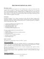
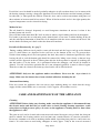
WARNINGS
General
• Read the instructions carefully before installation, use and maintenance of the appliance.
• Installation must be carried out by qualified personnel following the manufacturer’s instructions
in the specific manual.
• The appliance must only be used by trained personnel and only for the intended use.
• In the event of breakdown or malfunctioning, switch off the appliance and call in after sales
assistance only from an authorized centre.
• Use only original spare parts; otherwise no liability is accepted by the manufacturer.
• The appliance must not be washed with high pressure water sprays, neither must the openings or
be blocked.
ATTENTION! The manufacturer declines any liability for damage caused by wrong
installation, tampering, making unauthorized changes, improper use, poor maintenance,
installation of non-original spare parts, not observing local norms, incorrect use or not
observing the instructions in this booklet
For the installer
• The functioning of the appliance must be explained and shown to the user. After having ensured
that everything is clear, the instruction booklet must be handed over.
• The user must be informed that any building modification or restructuring that may in any way
modify the air supply necessary for combustion, makes it necessary to carry out another check of
the functionality of the appliance.

Pag. 41/63
TECHNICAL FEATURES
The following instructions for set up and functioning refer to gas and mixed appliances belonging to
categories I
3B/P
, II
2H3+
, II
2H3B/P
,
II
2HS3B/P
, III
1ab2H3B/P,
II
2ELL3B/P
with a power pressure for
Buthane/Propane (G30- G31) of 30/37 mbar (50 mbar for II
2ELL3B/P
category) , for Methane (G20-
G25- G25.1) of 20/25 mbar, and for Town Gases (G110-120) of 8mbar. The data plate (fig. 5 – pag.
4) with all the information to refer to regarding the appliance, is situated inside the right or left side
of the control panel, depending on the model.
The appliances have been checked in accordance with the European directives below.
2006/95/CE - Low Tension (LVD)
CEE 2004/108 - Electromagnetic Compatibility (EMC)
90/396/EEC - Gas Appliances
98/37/EC - Appliance to the directives
And the particular reference norms.
Declaration of compliance
The manufacturer declares that the appliances of their production are compliant with the above
mentioned EEC directives and requires that installation be done observing the norms in force,
regarding particularly the system for letting out fumes and air exchange.
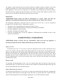
DESCRIPTION OF APPLIANCES
Gas Fryer
A sturdy structure in steel placed on four feet, which make it possible to regulate the height in
the version with cabinet. The external coating is in Chrome-Nickel 18-10 stainless steel.
Each vat is provided with a thermostatic safety gas valve, which enables the regulation of the
temperature in a range from 100° C to 190° inclusive; safety is ensured by means of a thermo-
couple, which is kept active by the flame of the pilot burner.
The vat is made entirely of stainless steel.
It is heated by means of a stainless steel tubular burner, suitable for proper functioning at the high
temperatures to which it is exposed
Electric Fryer
A sturdy structure in steel placed on four feet, which make it possible to regulate the height in
the version with cabinet. The external coating is in Chrome-Nickel 18-10 stainless steel.
It is provided with a thermostat which makes it possible to regulate the temperature in a range from
100° C to 190° C inclusive, safety is ensured by a manually operated safety thermostat.
The vat is entirely of stainless steel.
It is heated by an electric immersion heater, which is immersed in the oil.

Pag. 42/63
PROVISIONS FOR INSTALLATION
Place (fig.6 – pag.4)
It is advisable to install the appliance in a well ventilated room or under an extractor hood. The
appliance may be installed as a single unit or together with others. In both cases, if it is installed
near a wall of inflammable material, a minimum distance of 100mm from the side and back walls
must be observed. In the event that it is not possible to observe this distance, protective measures
must be taken (e.g. use of sheets of refractory material) which ensure that the temperature of the
walls is within the established safety limits.
Installation
Installation operations, gas or voltage conversions to other than the original, starting up the
installation or appliance, ventilation, letting out fumes, and maintenance must be done following the
manufacturer's instructions and observing the norms in force, by qualified personnel, in compliance
with the following provisions (GB):
Gas Safety (Installation and Use) Regulations, 1984
Health and Safety at Work Act, 1974
Codes of Practice, BS6173, 1982
The Building Regulations, 1985
The Building Standards Regulations, 1981
For others countries follow the relevant local rules for:
Gas board rules
Building regulations and local fire prevention provisions
Safety norms in force
Provisions of the Gas supplying company
The Electrical Norms in force
The Fire Brigade rules
Fumes evacuation
The appliances are divided into two types (see Table 1 - pag.36):
Type "A1" gas appliances
It is not necessary to connect this type of appliance directly to an evacuation pipe for combustion
products. The products of combustion, however, must be directed into suitable hoods or similar
devices, connected to a reliably efficient chimney, otherwise directly outside.
The use of an extractor fan connected directly to external environment with a capacity no lower
than what is stated in table 1.
This value must be increased with the air exchange necessary for the well-being of the operators, in
accordance with the norms in force. (approximately a total of 35 m
3
/h per KW of gas output
installed).
Type “B11” gas appliance
These appliances must be connected in one of the following ways:

Pag. 43/63
• Natural evacuation (fig.7 – pag.5).
Connection to reliable chimney with natural pull, interposing a pull device, letting out the
products of combustion directly outside.
• Direct forced evacuation (fig.8 – pag.5).
Connection to a chimney with forced pull, putting in a pull device, letting out the products of
combustion directly into external environment. The energy supply to the appliance must be
controlled by the system of forced evacuation and must be interrupted in the event that its
capacity falls below the values prescribed by the norms in force.
It must only be possible to restart the gas supply manually.
• Forced evacuation under hood (fig.9 – pag.5).
In this case, the fumes evacuation device of the appliance must be brought to a height of 1,8 m
from floor level, and the putlet section of the evacuation pipes for products of combustion must
be placed inside the base perimeter of the hood. The energy supply to the appliance must be
controlled by the system of forced evacuation and must be interrupted in the event that its
capacity falls below the values prescribed by the norms in force. It must only be possible to
restart the gas supply manually.
INSTALLATION
Preliminary operations
Remove the appliance from the packaging, ascertaining that it is intact and, if in doubt, do not use it
but call in professionally qualified personnel. After having verified that the appliance is in good
condition, the protective film may be removed. Carefully clean the external parts of the appliance
with warm water and detergent using a cloth to remove all remaining residues and then dry it with a
soft cloth. If there are still traces of glue residues, remove them by using a suitable solvent (e.g.
acetone): For no reason use abrasive substances. After having been put into place, the appliance
must be levelled by regulating the adjustable feet.
Gas Connection
Before connecting the appliance, it is necessary to check that the type of gas available corresponds
to the type of gas the appliance has been set for. In the event that they do not correspond, it is
necessary to proceed as described in the paragraph “Functioning with gas different from the
setting”. The connection to the threaded coupling, having a diameter of ½ inch, situated on the
bottom of the appliance, may be fixed or mobile using a compliant rapid pipe fitting. If flexible
piping is used, this must be in stainless steel and compliant with the norm. All the seals on the
junction threads must be in guaranteed materials certified for use with gas. Before the installation of
each single appliance it is necessary to install a cutoff cock for rapid interruption of the gas supply,
placed in an easily accessible position in such a way as to make it possible to turn off the gas supply
when the appliance is not being used. When the connection has been completed, the tightness must
be checked by using a leak-finder spray.

Pag. 44/63
Electric connection
Before connecting the appliance, it is necessary to check that the voltage of the power supply
available corresponds to the voltage the appliance has been set for. In the event that they do not
correspond, it is necessary to modify the connection as shown in the electric diagram, if voltage
change is provided for. The terminal blocks are situated behind the instrument board. Furthermore,
the efficiency of the earth connection must be checked, and also that the earth conductor on the
connecting side is longer than the other conductors, and that the connecting cable has a wire bunch
adequate for the power absorbed by the appliance and is at least type H05 RN-F. As in
international provisions, before installing the appliance a unipolar device must be installed
with a contacts opening of at least 3mm which must not interrupt the YELLOW-GREEN
earth wire. The device must be installed near the appliance, it must be approved and have adequate
capacity for the absorption of the appliance (see technical features).
The appliance must be connected to the EQUIPOTENZIALE system. The connector is situated near
the end of the electric cable and is identified by a label with the symbol shown on figure 10 (pag.5).
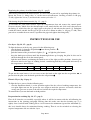
Checking gas tightness and pressure (fig.11 – pag.5)
Before proceeding to check the pressure, it is necessary to check the tightness of the gas installation
up to the nozzle with a leak-finder spray to ensure that no damage has been done to the appliance
during transportation. Then it is possible to proceed with checking the inlet pressure, which is done
by means of a gauge for liquids , either a "U" gauge or an electronic gauge with a minimum
definition of 0,1 mbar. To carry out the reading, the screw (1) must be removed from the pressure
outlet (2) and the rubber pipe of the gauge connected. Open the gas supply valve of the appliance,
check the pressure output and close the valve. Remove the pipe of the gauge and put back the
screws correctly into the pressure outlet. The pressure valve must be within the minimum and
maximum values shown below:
(*These gases belong to II
2HS3B/P
category, which is used only in Hungary)
If the pressure reading is not within the limits of the table, find out the cause. After solving the
problem, check the pressure again.
Checking the power
Normally, it is sufficient to check that the nozzles installed are the right ones and that the burners
function properly. If desired, further check the power absorbed by using the "Volumetric Method".
With the help of a chronometer and a counter, it is possible to read the volume of gas output to the
appliance in time units. The right comparison volume [E] can be obtained with the formula shown
overleaf in litres per hour (l/h) or in litres per minutes (l/min), by dividing the nominal and
minimum outputs (power) shown in the table of burner features for the lowest heat capacity of the
Type of gas
P
n
[mbar]
P
min
[mbar]
G20 (Methane) 20 17
G20 (Methane)* 25 20
G25 (Methane) 25 20
G25.1 (Methane)* 25 20
G30 (Butane) 30 20
G31 (Propane) 37 25

Pag. 45/63
type of gas foreseen for use with the appliance. This value can be found in the norm tables or can be
provided by the local gas supply company.
The reading must be done when the appliance is already in function.
Checking pilot burner
Check the flame of the pilot burner, which must be neither too short nor too high but must lap the
thermocouple and have a sharp form; otherwise, it is necessary to check the size of the nozzle
depending on the pilot version, as specified in the following paragraphs.
Checking regulation of primary air
All the main burners are provided with primary air regulation. Checking must be done observing the
values shown in the air regulation column of the burner features tables (pag.37÷40). To regulate the
primary air, proceed as illustrated in the following paragraphs.
ATTENTION! All the parts, protected and sealed by manufacturer may not be regulated by
the installer if not specifically indicated.
REGULATIONS AND SUBSTITUTION FOR USING A
DIFFERENT GAS TO THE TYPE PROVIDED FOR
Functioning with different gas to the type provided for.
For changing to another type of gas it is necessary to substitute the nozzle in the main burners and
in the pilot burner, following the indications given in the following paragraphs. The type of nozzle
to install can be found in tables 2-10 (pag. 37÷40). The nozzles for the main burner, marked with
the relative diameter in hundredths, and the ones for the pilot burner, marked with a number, can be
found in a transparent packet attached to the instruction booklet.
When the conversion is completed, check the tightness of the pipe fittings and also that the ignition
and functioning of both the pilot burner and main burner, at both minimum and maximum, are
correct. It may be necessary to check the output (power).
Substituting the burner nozzle (fig.12 – pag.5)
To substitute the burner nozzle, open the compartment door and unscrew the nozzle (1) from the
nozzle holder (2), and open it completely, unscrew the nozzle (3) with a spanner and substitute it
with the nozzle suitable for the type of gas to be used, shown in tables 2÷10 (pag. 37÷40). Put back
the nozzle, tightening it well and proceed to regulate the primary air, as indicated in the next
paragraph.
Power
Heat capacity
E =

Pag. 46/63
Regulating the primary air of the burner (fig. 12 – pag.5)
After having substituted the burner nozzle, it is necessary to proceed by regulating the primary air:
loosen the screw (1), bring value "x" to the correct measurement, referring to tables 2÷10 (pag.
37÷40), tighten the screw (1) and check the accuracy of value "x".
Substituting the pilot burner nozzle (fig. 13 – pag.6)
To substitute the pilot burner nozzle, open the compartment door and remove the control panel.
Unscrew the nut, which fixes the thermocouple to the nozzle holder and slide it off; then unscrew
the fitting (1), which fixes the gas supply pipe to the pilot (2) and take out the nozzle (3). Substitute
it with the nozzle suitable for the type of gas to be used, shown in tables 2÷ 10 (pag. 37÷40). Then
proceed to assemble the new nozzle, reposition the pipe and tighten the fitting fully.
INSTRUCTIONS FOR USE
Gas fryer (fig. 14, 15 – pag.6)
To light the burner of the fry top, proceed in the following way:
- turn the knob (1) from the off position
into the on position ;
- press down to the bottom;
- push the button of the piezoelectric lighter (2) to light the pilot burner;
- keep the knob pressed down until the thermocouple heats up, keeping the pilot lit; this can be
checked through the slit in the control panel;
- light the main burner, positioning the knob in one of the eight possible positions, choosing the
one most suited to the type of cooking desired, considering that they correspond indicatively to
the temperatures shown below:
To put out the main burner, it is necessary to turn the knob to the right into the on position , to
put out also the pilot, turn the knob again into the off position
.
Electric Fryer (fig. 23 pag. 8)
To light the fryer, proceed in the following way:
- turn the thermostat knob (1) to the position required for the selected cooking temperature, the
two pilot lights turn on; the green one stays alight to mark the presence of tension, while the
orange one goes out as soon as the oil has reached the required temperature.
To turn off the fryer turn the knob to the 0 position.
Preparation for cooking (fig. 16, 17 – pag.6)
First of all clean the vat carefully especially where it will be in contact with the oil following the
instructions in the cleaning paragraph. Having done this make sure that the draining tap (1) is
tightly closed, and fill with cooking oil to a level between the minimum sign and the maximum (2),
this level should always be maintained during cooking. Then it can be switched on selecting the
required temperature for use with the fryer.
Position [N°] 1 2 3 4 5 6 7
Temperature [°C] 100 115 130 145 160 175 190

Pag. 47/63
If solid fat is used it should be melted gradually otherwise it will overheat where it is in contact with
the heating element creating a dangerous situations. First of all the baskets and the bottom grid must
be taken out (3). Then put in the solid fat. Then the fryer can be used for one minute with pauses of
three minutes in between until it has melted. When all fat has melted and it is the right quantity the
required temperature can be selected for frying.
Method of use
The oil should be changed frequently to avoid dangerous situations do not use it when it has
become brown and viscose.
Never fill the basket more than 50% full, in order to achieve rapid cooking and low oil absorption.
If a basket is put into the vat with only partly drained food, it can cause a sudden boiling of the oil
and the subsequent formation of foam due to oil emulsion with the water content of the food. Lift
out the basket and then put it back so that the foam will condense.
Periodic oil filtration (fig. 18 – pag.7)
During cooking different sized particles come off the food and the largest end up on the bottom
grid (3), while others are deposited in the cold area at the bottom of the vat. To prevent these
residues from ruining the oil and consequently the food, they must be eliminated periodically. After
leaving the oil to cool the bottom grid should be removed by lifting it out slowly so that no large
residues will be dispersed in the oil. Having done this the drain tap must be opened (4) making sure
that the basket (5) in the basin (6) is positioned below the drainpipe, and all the oil should be
drained. If at the end of this operation the oil is not adequately purified, it must be filtered again.
Then the vat must be cleaned, the drain tap closed and it can be filled with oil.
ATTENTION! Only use the appliance under surveillance. Never use the fryer when it is
empty. Make sure the burners have been switched off before draining the oil.
Abnormal functioning
If for any reason, the appliance does not start or stops working during use, check that the energy
supply and the control knobs are set correctly; if all is regular, call customer service.
CARE AND MAINTENANCE OF THE APPLIANCE
Cleaning
ATTENTION! Before doing any cleaning, make sure that the appliance is disconnected from
the electric mains and that the gas cutoff valve is closed. During cleaning operations, avoid
using direct or high pressure sprays of water on the appliance. Cleaning must be done when
the appliance is cold.
The parts in steel can be cleaned with warm water and neutral detergent, using a cloth; the detergent
must be suitable for cleaning stainless steel and must not contain abrasive or corrosive substances.
Do not use common steel wool or anything similar which, depositing iron particles, could cause rust
from it. It is also better to avoid using sandpaper or emery paper. Only in the event of encrusted
Page is loading ...
Page is loading ...
-
 1
1
-
 2
2
-
 3
3
-
 4
4
-
 5
5
-
 6
6
-
 7
7
-
 8
8
-
 9
9
-
 10
10
-
 11
11
-
 12
12
-
 13
13
-
 14
14
-
 15
15
-
 16
16
-
 17
17
-
 18
18
-
 19
19
-
 20
20
-
 21
21
-
 22
22


Bartscher 286922 Operating instructions
- Category
- Deep fryers
- Type
- Operating instructions
Ask a question and I''ll find the answer in the document
Finding information in a document is now easier with AI
Related papers
-
Bartscher 1519821 Operating instructions
-
Bartscher 1519811 Operating instructions
-
-
-
Bartscher 132115 Operating instructions
-
-
Bartscher 2856011 Operating instructions
-
Bartscher 286106 Operating instructions
-
-
Bartscher 1311413 Operating instructions
Other documents
-
Falcon F900 G9881 User, Installation And Servicing Instructions
-
-
Maxima 09395017 Owner's manual
-
GGM Gastro GWHK1 Owner's manual
-
GGM Gastro EON20 Owner's manual
-
-
Diamond BRET/1G-HR Operation And Installation Instructions
-
Electrolux NCPE2RU Operating instructions
-
ROLLER GRILL RFG 12 (GP318-P) Owner's manual
-
Whirlpool AGB 357/WP User guide