
Quick Installation Guide
LED Indicators
Getting to know your device
Ports & Button
5GHz 11n 300Mbps Basestation
B6
If any item is missing or damaged, please keep the original package and
contact the local reseller or distributor immediately. For product or function
details, please go to www.tendacn.com
Package Contents
Basestation x 1
PoE adapter x 1
Power cord x 1
Metal strap x 1
Grounding screw x 1
Quick installation guide x 1
DescriptionStatusLED Indicators
Power
Solid on The device is powered on properly.
O The device is not powered on or not powered on properly.
PoE/LAN
Solid on
Blinking
O
The port is connected properly, but no data is transmitted.
Data is being transmitted over the port.
The port is not connected, or not connected properly.
LED1, LED2, LED3
(Received signal
strength LED
indicators)
Solid on
Bridged successfully. The device may work in AP, Repeater, P2MP or Router mode.
LED1, LED2 and LED3 are solid on: Good signal
LED1 and LED2 are solid on, and LED3 is o: Fair signal
LED1 is solid on, and LED2 and LED3 are o: Weak signal. Please adjust the
direction or location of the two bridging devices.
Tip:
By default, the minimum signal strength of LED1, LED2 and LED3 are -90 dBm, -80
dBm and -70 dBm. You can change them on the Wireless > Advanced page of the
web UI of the device.
Bridged successfully. The device may work in Client, Universal Repeater or WISP
mode.
LED1, LED2 and LED3 are blinking: Good signal
LED1 and LED2 are blinking, and LED3 is o: Fair signal
LED1 is blinking, and LED2 and LED3 are o: Weak signal. Please adjust the
direction or location of the two bridging devices.
The received signal strength does not reach the minimum RSSI threshold of the
Base Station, or the bridging fails. Please adjust the direction or location of the
two bridging devices.
Blinking
O
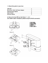
GND
Reset
PoE/LAN
Port/Button Description
GND terminal.
Used for ESD and lightning protection.
Use a grounding cord and the included grounding screw to
connect this GND terminal to the earth.
Reset Button.
When the Power LED indicator lights solid on, hold down this button
for about 8 seconds, then release it. When all the LED indicators light
up and then turn o, the device is restored to factory settings.
It is used to supply power or transmit data.
Use the included PoE adapter to supply power to the Base Station.
CAT5e or better Ethernet cable is recommended, and the length
should not exceed 60 meters.
4. Connect the other side of the RF coaxial cables to the connectors
of the antenna.
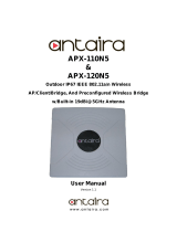
Pole mounting
1. Use a screwdriver to open the metal strap by turning the screw
counter-clockwise.
2. Straighten out the end of the metal strap, and thread it through
the back of the Base Station, wrap the metal strap around the
pole, and tighten the strap by turning the screw clockwise using
the screwdriver.
GND Reset PoE/LAN
PoE/LANResetGND
Caution
Adapter Model: BN060-P12024
Manufacture: SHENZHEN HEWEISHUN NETWORK TECHNOLOGY CO., LTD.
Input: 100 - 240V AC, 50/60Hz 0.3A
Output: 24V DC, 0.5A
: DC Voltage
FCC Statement
This equipment has been tested and found to comply with the limits for a Class A
digital device, pursuant to Part 15 of the FCC Rules. These limits are designed to
provide reasonable protection against harmful interference in a residential
installation. This equipment generates, uses and can radiate radio frequency energy
and, if not installed and used in accordance with the instructions, may cause harmful
interference to radio communications. However, there is no guarantee that
interference will not occur in a particular installation. If this equipment does cause
harmful interference to radio or television reception, which can be determined by
turning the equipment o and on, the user is encouraged to try to correct the
interference by one or more of the following measures:
— Reorient or relocate the receiving antenna.
— Increase the separation between the equipment and receiver.
— Connect the equipment into an outlet on a circuit dierent from that to which the
receiver is connected.
— Consult the dealer or an experienced radio/TV technician for help.
Operation is subject to the following two conditions: (1) this device may not cause
harmful interference, and (2) this device must accept any interference received,
including interference that may cause undesired operation.
Radiation Exposure Statement
This device complies with FCC radiation exposure limits set forth for an uncontrolled
environment and it also complies with Part 15 of the FCC RF Rules.
This equipment should be installed and operated with minimum distance 20cm
between the device and your body.
Caution:
Any changes or modications not expressly approved by the party responsible for
compliance could void the user's authority to operate this equipment.
This transmitter must not be co-located or operating in conjunction with any other
antenna or transmitter.
Operating frequency: 5150-5250MHz, 5725-5850MHz
NOTE: (1) The manufacturer is not responsible for any radio or TV interference caused
by unauthorized modications to this equipment. (2) To avoid unnecessary radiation
interference, it is recommended to use a shielded RJ45 cable.
Operating Temperature: -30 °C - 60 °C
Operating Humidity: 10% - 90% RH, non-condensing
RECYCLING
This product bears the selective sorting symbol for Waste electrical and electronic
equipment (WEEE). This means that this product must be handled pursuant to
European directive 2012/19/EU in order to be recycled or dismantled to minimize
its impact on the environment.
User has the choice to give his product to a competent recycling organization or to
the retailer when he buys a new electrical or electronic equipment.
For EU/EFTA, this product can be used in the following countries:
CE Mark Warning
This is a Class A product. In a domestic environment, this product may cause radio
interference, in which case the user may be required to take adequate measures.
Operations in the 5.15-5.25GHz band are restricted to indoor use only.
This equipment should be installed and operated with a minimum distance 20cm
between the device and your body.
WARNING: The mains plug is used as disconnect device, the disconnect device shall
remain readily operable.
NOTE:
(1) The manufacturer is not responsible for any radio or TV interference caused by
unauthorized modications to this equipment.
(2) To avoid unnecessary radiation interference, it is recommended to use a
shielded RJ45 cable.
Declaration of Conformity
Hereby, SHENZHEN TENDA TECHNOLOGY CO., LTD. declares that the radio
equipment type B6 is in compliance with Directive 2014/53/EU.
The full text of the EU declaration of conformity is available at the following
internet address: http://www.tendacn.com/en/service/download-cata-101.html
Operating Frequency: EU/5150-5250MHz (CH36-CH48); EIRP Power (Max.): 22.98dBm
EU/5470-5725MHz (CH100-CH140); EIRP Power (Max.): 26.98dBm
Software Version: V1.0.0.6
Copyright
© 2019 Shenzhen Tenda Technology Co., Ltd. All rights reserved.
is a registered trademark legally held by Shenzhen Tenda Technology Co., Ltd.
Other brand and product names mentioned herein are trademarks or registered
trademarks of their respective holders. Specications are subject to change without
notice.
Technical Support
Shenzhen Tenda Technology Co., Ltd.
6-8 Floor, Tower E3, NO.1001, Zhongshanyuan Road, Nanshan District, Shenzhen,
China. 518052
USA hotline: 1-800-570-5892
Toll Free: Daily-9am to 6pm PST
Canada hotline: 1-888-998-8966
Toll Free: Mon - Fri 9 am - 6 pm PST
Hong Kong hotline: 00852-81931998
Global hotline: +86 755-2765 7180 (China Time Zone)
Website: http://www.tendacn.com
E-mail: [email protected]
After the bridging succeeds, all O4 work in Client mode, and their
IP addresses are changed to 192.168.2.2.
Base Station: AP mode
LED1, LED2 and LED3 are solid on
O4-20: Client mode
LED1, LED2 and LED3
are blinking
O4-1: Client mode
LED1, LED2 and LED3
are blinking
Refer to the conguration procedure in Scenario 1: PtP backhaul
connection with dish antennas to set the Base Station to the
AP mode, and set all O4 to Client (Station) mode.
Option 2: Setting up the Base Station and
O4 using the web UI
Bracket mounting
Installing the device
Installation notes
1. Press the handle on the mount bracket, align the four hooks on
the panel of the Base Station with the four slots on the bracket,
and slide the Base Station to x it onto the bracket.
The Base Station can work with the dish, sector or other antenna (purchased separately).
2. Remove the plastic screw caps on the RP-SMA connectors of
the Base Station.
3. Connect one side of two RF coaxial cables (enclosed with the
antennas) to the RP-SMA connectors of the Base Station.
3. Remove the plastic screw caps on the RP-SMA connectors of the
Base Station.
4. Connect one side of two RF coaxial cables (enclosed with the
antennas) to the RP-SMA connectors of the Base Station.
5. Connect the other side of the RF coaxial cables to the connectors
of the antenna.
Lightning and ESD protection
Connect the GND terminal of the Base Station to a grounding
terminal conencted the earth or building to protect the Base
Station from overvoltage and overcurrent caused by lightning
and ESD.
Base Station
GND terminal
Grounding cord
Earth
1. Connect one side of a grounding cord to the included
grounding screw.
2. Conenct the grounding screw to the GND terminal of the Base
Station, and tighten it.
3. Connect the other side of the grounding cord to the grounding
terminal connected to the earth or building.
PoE/LANResetGND
4. Select the SSID you set on the rst Base Station, which is
Tenda_123456 in this example, and click Next.
Tenda_123456
Tenda_123456 157 WPA2-PSK,AES
Click "Scan", and select the wireless network you want to connect,
and click "Next".
Scan
Upstream AP
SSIDSelect Channel MAC Address Security Mode
Signal
Strength
Scan Again
C8:3A:35:14:48:62
5. Enter the WiFi password you set on the rst Base Station in the Key
text box, and click Next.
Tenda_123456
WPA2-PSK
AES TKIP TKIP&AES
Channel
Encryption Algorithm
Key
Security Mode
C8:3A:35:14:4B:62
Ensure that the device uses the same channel, encryption, and encryption algorithm as those of upstream AP.
Then enter the remote AP's WiFi password, and click "Next" to continue.
Upstream AP
Upstream AP MAC Address
157(5785MHz)
6. Set the IP address to an unused IP address belonging to the
same network segment as that of the rst Base Station. For
example, if the IP address of the rst Base Station is
192.168.2.1, you can set the IP address of this Base Station to
192.168.2.X (X ranges from 2 to 254). Then click Next.
IP Address
Subnet Mask
Set the IP address to an unused IP address belonging to the network segment of upstream AP.
192.168.2.100
255.255.255.0
7. Click Save, and wait until the Base Stations reboot to activate
the settings.
The device is set to WISP. Please click “Save” to apply the settings.
When LED1, LED2, and LED3 of the Base Station in AP mode are
solid on, and LED1, LED2, and LED3 of the base Station in Client
(Station) mode are blinking, the bridging succeeds. The DHCP
servers of the two Base Stations are disabled automatically.
Quick Setup >> Client
?
Quick Setup >> Client
?
NextPrevious NextPrevious SavePrevious
Quick Setup >> Client
?
Quick Setup >> Client
?
3. Select Client (Station), and click Next.
Next
Select a working mode:
Quick Setup
AP
In this mode, the device creates a wireless network based on the current wired network.
Client (Station)
In this mode, the device works as a wireless adapter to connect to the wireless network of upstream AP.
Universal Repeater
In this mode, this device extends an existing wireless network for broader network coverage.
WISP
In this mode, this device connects to an access point provided by ISP in wireless manner, and provides the wireless network.
Repeater
In this mode, the device connects to multiple wired networks through wireless bridge, and provides wireless access point.
P2MP
In this mode, the device connects to multiple wired networks through wireless bridge, but does not provide wireless access point.
Router
connect to modem in wired manner, and provide network access point
?
Tips:
If the login page doesn’t appear, please refer to Q1 in FAQ.
Step 4: Set the other Base Station to Client (Station) mode.
1. Perform Step 2 Connect a computer to the Base Station to
connect the computer to the other Base Station.
2. Start a web browser on the computer, and visit 192.168.2.1.
Enter the login user name and password, and click Login.
Default user name: admin
Forge t pa ssword?
L ogi n
192.168.2.1
English
Default password: admin
O2V1.0
Default user name: admin
Forget password?
Login
192.168.2.1
English
Default password: admin
B6V1.0
Scenario 1: PtP backhaul connection with dish antennas
One Base Station in AP mode and another one in Client (Station)
mode create a long distance wireless connection for point to point
connection.
Step 1: Place two Base Stations next to each other.
Step 2: Connect a computer to a Base Station.
PoE LAN
Base Station
PoE/LANResetGND
Computer
PoE adapter
Step 3: Set the Base Station to AP mode.
Tip:
If the login page does not appear, please refer to Q1 in FAQ.
3. Set an SSID, which is Tenda_123456 in this example, Security
Mode
(WPA2-PSK is recommended), Channel, and Key, and
click Next.
SSID
WPA2-PSK
AES TKIP TKIP&AES
157(5185MHz)
You can set up your wireless network name and wireless password here.
Note down your wireless password.
Channel
Security Mode
Encryption Type
Key
Quick Setup >> AP
NextPrevious
Tenda_123456
4. Click Save, and wait until the Bastion Station reboots
automatically to activate the settings.
ISP Room
Base Station + Dish Antenna Base Station + Dish Antenna
Internet
Point to Point Backhaul Connection
1. Remove the cover of the Base Station.
2. Use an Ethernet cable (CAT5e or better Ethernet cable is
recommended) to connect the PoE/LAN port of the Base Station
to the PoE port of the PoE adapter.
3. Connect the PoE adapter to a power source. The PoE/LAN LED
indicator of the Base Station lights up.
4. Use an Ethernet cable to connect your computer to the LAN port
of the PoE adapter.
1. Start a web browser on the computer, and visit 192.168.2.1.
Enter the login user name and password, and click Login.
2. Select AP, and click Next.
Next
Select a working mode:
Quick Setup
AP
In this mode, the device creates a wireless network based on the current wired network.
Client (Station)
In this mode, the device works as a wireless adapter to connect to the wireless network of upstream AP.
Universal Repeater
In this mode, this device extends an existing wireless network for broader network coverage.
WISP
In this mode, this device connects to an access point provided by ISP in wireless manner, and provides the wireless network.
Repeater
In this mode, the device connects to multiple wired networks through wireless bridge, and provides wireless access point.
P2MP
In this mode, the device connects to multiple wired networks through wireless bridge, but does not provide wireless access point.
Router
connect to modem in wired manner, and provide network access point
? ?
Default user name: admin
Forge t pa ssword?
L ogi n
192.168.2.1
English
Default password: admin
O2V1.0
Default user name: admin
Forget password?
Login
192.168.2.1
English
Default password: admin
B6V1.0
Scenario 2: P2MP connection with sector antennas
The Base Station in AP mode can provide WiFi network, allowing
home users or small oce users to connect to the WiFi network
with outdoor long range CPEs. The Base Station can work with
Tenda O2 or O4. O4 is used for illustration here.
2. Remove the covers of the Base Station and O4, and use Ethernet
cables (CAT5e or better Ethernet cable is recommended) to
connect their PoE/LAN ports to the PoE ports of the included PoE
adapters respectively.
3. Use the power cords to connect the PoE adapters to power
sources. When PoE/LAN LED indicators of the Base Station and
O4 light up, they completes startup.
Base Station: AP Mode
LED1, LED2 and LED3 are solid on
Step3: Within 3 minutes after the peer-to-peer bridging succeeds,
power on the rest O4.
Step4: Wait for about 1 minute. When the LED1, LED2, and LED3
of these O4 are blinking, the bridging succeeds.
O4: Client Mode
LED1, LED2 and LED3 are blinking
Option 1: Automatic bridging (recommend)
Tips:
Automatic bridging is only applicable when the Base Station and
CPE are in factory settings.
Ensure that only the Base Station and one CPE are powered on
when performing peer-to-peer bridging. Otherwise, the
peer-to-peer bridging may fail.
When the Base Station and CPE are powered on using Ethernet
cables, CAT5e or better Ethernet cable is recommended, and the
length should not exceed 60 meters.
For peer-to-multiple peers bridging, perform peer-to-peer
bridging rst, and then power on the rest CPEs within 3 minutes.
Otherwise, the bridging may fail.
A Base Station can bridge to 20 CPEs at most.
Internet
ISP Network Base Station + Sector Antenna
P2MP Link Connection
Small Oce
Residence
Internet Café
Step1: Prepare a Base Station and 20 CPEs (O4), and put all O4
near the Base Station.
Step2: Choose one O4 to perform peer to peer bridging with
the Base Station.
O4
PoE/LANGND Reset
Base Station
PoE/LANResetGND
1. Place the Base Station and the O4 next to each other.
Within 1 minute, the Base station and O4 will perform automatic
bridging. When the bridging succeeds, the DHCP servers of the
Base Station and O4 are disabled. O4 works in Client mode and
its IP address is changed to 192.168.2.2.
FAQ
Q1: I cannot log in to the web UI of the Base Station by entering 192.168.2.1.
What should I do?
Q2: How to reset the Base Station to factory settings?
Q3: How to determine whether the bridging signal strength is optimal
when the Base Station is used for bridging?
Q4: The automatic bridging fails. What should I do?
Stronger signal strength (-60 is better than -70) and less background noise
(-100 is better than -90) lead to better bridging signal.
A4: Try the following solutions:
If the peer-to-peer bridging fails, reset the Base Station and O4 to factory
settings, and try again.
If the peer-to-multiple bridging fails, ensure that the new added O4 is
powered on within 3 minutes after the peer-to-peer bridging succeeds.
If the problem persists, reset the Base Station and all O4, and try again.
Q5: When the bridging succeeds, the LED1, LED2, and LED3 indicators do
not light up or only one or two of them light up. What should I do?
A5: Try the following solutions:
Place the Base Station and O4 in an elevated location with few obstacles
nearby.
Adjust the Base Station in horizontal and vertical directions slowly. Wait
for 20 to 30 seconds after you choose a direction. Observe the LED1,
LED2 and LED3 indicators of the Base Station when you are adjusting the
CPE until all of LED1, LED2 and LED3 indicators lights up.
Wireless Status
Working Mode
SSID
Security Mode
Channel/Radio Band
Channel BandWidth
TX Power
Wireless Client
AP’s MAC Address
Signal Strength
Background Noise
TX/RX Link
Transmit/Receive Speed
TD-MAX
Client
N/A
N/A
157/5785MHz
40MHz
23dBm
N/A
C8:3A:35:88:88:91
3X3
216mbps/216Mbp...
Disabled
-65dBm
-116dBm
A1: Try the following methods:
Ensure that the Base Station has been connected to the power supply and
the computer properly.
Ensure that the IP address of the login computer is 192.168.2.X (X ranges
from 2 to 254, which is not used by other devices).
Restore the Base Station to factory settings.
A2: Note: Resetting the Base Station clears all settings, and you need to
congure it again.
Method One: 1 minute after the Power LED indicator lights up, remove the
cover of the Base Station, and hold down the Reset button
for about 8 seconds. When all LED indicators light up once,
the Base Station is restored to factory settings.
Method Two: Log in to the web UI of the Base Station, choose Tools >
Maintenance, and click the Reset button.
A3: Option One: Observe the signal strength LED indicators of the Base Station.
The bridging signal is optimum when all of the LED1, LED2 and LED3
indicators are solid on or blinking.
Option Two: Log in to the web UI of the Base Station, choose Status, and
check the Wireless Status on the following page:
Power
LED1/LED2/LED3
PoE/LAN
PoE
PoE adapter
PoE
PoE adapter
O4-1
O4-2
O4-20
…
-
 1
1

Ask a question and I''ll find the answer in the document
Finding information in a document is now easier with AI
Related papers
Other documents
-
 ARGtek CPE2512 User manual
-
W-KING W-KING BT231 Cylinder Bluetooth Speaker Cover User manual
-
Perle IDS-710HP Managed PoE Switch User guide
-
Wansview P1 Automatic Pet Feeder Installation guide
-
 Vonets VAP11N Quick Setting Manual
-
Samsung 5G CPE Quick start guide
-
 Vonets Mini300 Quick Setting Manual
-
 PlantLink BST01 Installation guide
-
Comtrend Corporation WAP-EN900R User guide
-
 ANTAIRA APX-120N5 User manual


