Page is loading ...

INSTRUCTION MANUAL
CR9000 Measurement and
Control System
Revision: 5/05
Copyright (c) 1995-2005
Campbell Scientific, Inc.

Warranty and Assistance
The CR9000 MEASUREMENT AND CONTROL SYSTEM is warranted
by CAMPBELL SCIENTIFIC, INC. to be free from defects in materials and
workmanship under normal use and service for thirty-six (36) months from
date of shipment unless specified otherwise. Batteries have no warranty.
CAMPBELL SCIENTIFIC, INC.'s obligation under this warranty is limited to
repairing or replacing (at CAMPBELL SCIENTIFIC, INC.'s option) defective
products. The customer shall assume all costs of removing, reinstalling, and
shipping defective products to CAMPBELL SCIENTIFIC, INC. CAMPBELL
SCIENTIFIC, INC. will return such products by surface carrier prepaid. This
warranty shall not apply to any CAMPBELL SCIENTIFIC, INC. products
which have been subjected to modification, misuse, neglect, accidents of
nature, or shipping damage. This warranty is in lieu of all other warranties,
expressed or implied, including warranties of merchantability or fitness for a
particular purpose. CAMPBELL SCIENTIFIC, INC. is not liable for special,
indirect, incidental, or consequential damages.
Products may not be returned without prior authorization. The following
contact information is for US and International customers residing in countries
served by Campbell Scientific, Inc. directly. Affiliate companies handle
repairs for customers within their territories. Please visit
www.campbellsci.com to determine which Campbell Scientific company
serves your country. To obtain a Returned Materials Authorization (RMA),
contact CAMPBELL SCIENTIFIC, INC., phone (435) 753-2342. After an
applications engineer determines the nature of the problem, an RMA number
will be issued. Please write this number clearly on the outside of the shipping
container. CAMPBELL SCIENTIFIC's shipping address is:
CAMPBELL SCIENTIFIC, INC.
RMA#_____
815 West 1800 North
Logan, Utah 84321-1784
CAMPBELL SCIENTIFIC, INC. does not accept collect calls.

i
CR9000 Table of Contents
Overview..................................................................... OV-1
OV1. Physical Description ......................................................................OV-1
OV1.1 Basic System.........................................................................OV-1
OV1.2 Measurement Modules..........................................................OV-3
OV1.3 Communication Interfaces ....................................................OV-8
OV2. Memory and Programming Concepts ............................................OV-9
OV2.1 Memory.................................................................................OV-9
OV2.2 Measurements, Processing, Data Storage..............................OV-9
OV2.3 Data Tables..........................................................................OV-10
OV3. PC9000 Application Software .....................................................OV-10
OV3.1 Hardware and Software Requirements................................OV-11
OV3.2 PC9000 Installation.............................................................OV-11
OV3.3 PC9000 Software Overview................................................OV-11
OV4. Specifications...............................................................................OV-14
1. Installation.................................................................1-1
1.1 Enclosure.............................................................................................. 1-1
1.1.1 Connecting Sensors..................................................................... 1-1
1.1.2 Quick Connectors ....................................................................... 1-1
1.1.3 Junction Boxes............................................................................ 1-2
1.2 System Power Requirements and Options............................................ 1-3
1.2.1 Power Supply and Charging Circuitry........................................ 1-3
1.2.2 Connecting to Vehicle Power Supply......................................... 1-6
1.2.3 Solar Panels................................................................................. 1-7
1.2.4 External Battery Connection....................................................... 1-7
1.2.5 Safety Precautions....................................................................... 1-8
1.3 Humidity Effects and Control............................................................... 1-8
1.3.1 Desiccant..................................................................................... 1-8
1.3.2 Nitrogen Purging......................................................................... 1-8
1.4 Recommended Grounding Practices..................................................... 1-9
1.4.1 Protection from Lightning........................................................... 1-9
1.4.2 Effect on Measurements: Common Mode Range...................... 1-9
1.5 Use of Digital Control Ports for Switching Relays............................. 1-10
2. Data Storage and Retrieval......................................2-1
2.1 Data Storage in CR9000....................................................................... 2-1
2.1.1 Internal Static Ram...................................................................... 2-1
2.1.2 Internal Flash Memory................................................................ 2-1
2.1.3 9080 PAM Module — PCMCIA PC Card.................................. 2-2
2.2 Internal Data Format............................................................................. 2-2
2.3 Data Collection..................................................................................... 2-3
2.3.1 The Collect Menu ....................................................................... 2-4
2.3.2 RealTime Write File.................................................................... 2-6
2.3.3 Logger Files Retrieve.................................................................. 2-7
2.3.4 Via PCMCIA PC Card................................................................ 2-8

CR9000 Table of Contents
ii
2.4 Data Format on Computer.....................................................................2-9
2.4.1 Header Information.....................................................................2-9
2.4.2 TOA5 ASCII File Format .........................................................2-11
2.4.3 TOB1 Binary File Format.........................................................2-12
2.4.4 TOB2 Binary File Format.........................................................2-12
3. CR9000 Measurement Details................................. 3-1
3.1 Measurements using the CR9041 A/D..................................................3-1
3.1.1 Analog Voltage Measurement Sequence ....................................3-1
3.1.2 Single Ended and Differential Voltage Measurements...............3-3
3.1.3 Signal Settling Time....................................................................3-6
3.1.4 Thermocouple Measurements .....................................................3-7
3.1.5 Bridge Resistance Measurements..............................................3-14
3.1.6 Measurements Requiring AC Excitation...................................3-16
3.1.7 Influence of Ground Loop on Measurements ...........................3-16
3.2 CR9058E Isolation Module Measurements ........................................3-17
3.2.1 CR9058E Supported Instructions..............................................3-18
3.2.2 CR9058E Sampling, Noise and Filtering..................................3-20
3.3 CR9052 Filter Module Measurements................................................3-22
3.4 Pulse Count Measurements.................................................................3-25
4. CRBASIC - Native Language Programming .......... 4-1
4.1 Format Introduction..............................................................................4-1
4.1.1 Mathematical Operations ............................................................4-1
4.1.2 Measurement and Output Processing Instructions......................4-1
4.1.3 Inserting Comments Into Program..............................................4-2
4.2 Programming Sequence ........................................................................4-2
4.3 Example Program..................................................................................4-3
4.3.1 Data Tables..................................................................................4-4
4.3.2 The Scan — Measurement Timing and Processing ....................4-5
4.4 Numerical Entries .................................................................................4-6
4.5 Logical Expression Evaluation .............................................................4-7
4.5.1 What is true? ...............................................................................4-7
4.5.2 Expression Evaluation.................................................................4-7
4.5.3 Numeric Results of Expression Evaluation.................................4-7
4.6 Flags......................................................................................................4-8
4.7 Parameter Types....................................................................................4-8
4.7.1 Expressions in Parameters...........................................................4-9
4.7.2 Arrays of Multiplier Offsets for Sensor Calibration ...................4-9
4.8 Program Access to Data Tables............................................................4-9
5. Program Declarations.............................................. 5-1
6. Data Table Declarations and Output
Processing Instructions..................................... 6-1
6.1 Data Table Declaration .........................................................................6-1
6.2 Trigger Modifiers..................................................................................6-2
6.3 Export Data Instructions.......................................................................6-8
6.4 Output Processing Instructions.............................................................6-9

CR9000 Table of Contents
iii
7. Measurement Instructions.......................................7-1
7.1 Voltage Measurements ......................................................................... 7-3
7.2 Thermocouple Measurements............................................................... 7-3
7.3 Half Bridges.......................................................................................... 7-6
7.4 Full Bridges .......................................................................................... 7-9
7.5 Excitation/Continuous Analog Output ............................................... 7-10
7.6 Self Measurements.............................................................................. 7-11
7.7 Peripheral Devices.............................................................................. 7-12
7.8 Digital I/O........................................................................................... 7-21
7.9 CR9052DC Filter Module Measurements.......................................... 7-26
8. Processing and Math Instructions..........................8-1
9. Program Control Instructions..................................9-1
A. Keywords and Predefined Constants....................A-1
Index ....................................................................... Index-1

CR9000 Table of Contents
iv
This is a blank page.

OV-1
Overview
The CR9000 is a modular, multi-processor system that provides precision measurement
capabilities in a rugged, battery-operated package. The system makes measurements at a
rate of up to 100 K samples/second with 16-bit resolution. Higher sample rates and
resolutions can be attained using some of our higher end modules (CR9052E filter module,
or the CR9058E isolation module). The CR9000 Base System includes CPU, power
supply, and A/D modules. Up to nine I/O modules are inserted to configure a system for
specific applications. The on-board, BASIC-like programming language includes data
processing and analysis routines. PC9000 Windows
™
Software provides program
generation and editing, data retrieval, and realtime monitoring.
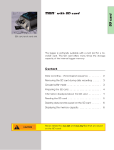
CR9000
AC ADAPTOR
FIGURE OV1-1. CR9000 Measurement and Control System
OV1. Physical Description
OV1.1 Basic System
CR9031 CPU Module
The CR9031 CPU Module provides system control, processing, and
communication to a PC via Transputer Link (TLINK) and fiber optic. The
main processor is a 32-bit Inmos T805 Transputer. The module has 2MB
static RAM and 2MB Flash EEPROM.

CR9000 Overview
OV-2
9031 CPU
FIBER OPTIC
LINK IN
FIBER OPTIC
LINK OUT TLINK
MADE IN USA
FIGURE OV1-2. CR9031
CR9041 A/D and Amplifier Module
The CR9041 A/D and Amplifier Module provides signal conditioning and 16
bit, 100 kHz A/D conversions.
9041 A D
CR9000
MEASUREMENT & CONTROL SYSTEM
LOGAN, UTAH
MADE IN USA
FIGURE OV1-3. CR9041
CR9011 Power Supply Module and AC Adapter
The CR9011 Power Supply Module provides regulated power to the CR9000
from the internal battery modules. It also regulates battery charging from
power supplied by the AC adapter, a DC input, or other external sources. The
AC adapter may be used where AC power is available (100 - 240 volts) to
provide power to the CR9000 and charge its batteries.
The CR9011 has a relay that allows shutting off power under program control.
The Power Up inputs allow an external signal to awaken the CR9000 from a
powered down state (PowerOff, Section 9). When the CR9000 is in this power
off state the ON Off switch is in the on position but the internal relay is open.
The power LED is not lit. If the "<0.5 " input is switched to ground or if the
">2" input has a voltage greater than 2 volts applied, the CR9000 will awake,
load the program in memory and run. If the "< 0.5" input continues to be held
at ground while the CR9000 is powered on and goes through its 2–5 second
initialization sequence, the CR9000 will not run the program in memory.
MEASUREMENTS:
Battery (voltage and current)
CONTROL:
PowerOff

CR9000 Overview
OV-3
9011 POWER SUPPLY
POWER
ON OFF
CHARGE(9-18VDC)
<0.8V
CHARGE
>2.0V
12VOUT POWER UP
MADE IN USA
FIGURE OV1-4. CR9011
OV1.2 Measurement Modules
CR9050(E) Analog Input Module
The CR9050(E) Analog Input Module has 14 differential or 28 single-ended
inputs for measuring voltages up to ±5 V. Voltages exceeding ±9 V may cause
errors on other channels. An on-board PRT provides the reference temperature
for thermocouple measurements, while a heavy copper grounding bar and
connectors combine with the case design to reduce temperature gradients for
accurate thermocouple measurements. Resolution on the most sensitive range
is 1.6 µV.
MEASUREMENTS:
Voltage
Differential Voltage (VoltDiff)
Single-Ended Voltage (VoltSE)
Thermocouple, Differential Voltage (TCDiff) Thermocouple, Single-Ended
Voltage (TCSE)
Bridge measurements (also require CR9060 Excitation Module)
Full Bridge (BrFull)
6 Wire Full Bridge (BrFull6W)
Half Bridge (BrHalf)
3 Wire Half Bridge (BrHalf3W)
4 Wire Half Bridge (BrHalf4W)
Module Temperature (ModuleTemp)
9050 ANALOG INPUT W RTD
SE
DIF
1
1
H
2
L
2
3
H
4
L
3
5
H
6
L
4
7
H
8
L
5
9
H
10
L
6
11
H
12
L
7
13
H
14
L
8
15
H
16
L
9
17
H
18
L
10
19
H
20
L
11
21
H
22
L
12
23
H
24
L
13
25
H
26
L
14
27
H
28
L
MADE IN USA
FIGURE OV1-5. CR9050
CR9051E Fault Protected 5V Analog Input Module
The number of channels and measurements are the same as for the CR9050
Analog Input Module. Each input channel is fault-protected so as to permit
over-voltages between +50 V and –40 V without corruption of measurements
on other input channels. All the CR9051E input channels become open
switches when the CR9000 is powered off. The CR9051E is recommended

CR9000 Overview
OV-4
over the CR9050E for applications where fault voltages beyond ±9 V could
come in contact with the inputs, or when the CR9000 could be powered off
while still connected to sensors that have power applied to them.
CR9051E FAULT MADE IN USA
CR9050EC
5V ANALOG INPUT CONNECTOR FOR CR9050E OR CR9051E MADE IN USA
FIGURE OV1-6. CR9051E
CR9052DC Anti-Alias Filter Module with DC Excitation
The CR9052DC is a high-performance anti-alias filter module that extends the
capability of the CR9000 Measurement and Control System. The module
includes six anti-aliased analog measurement channels with differential input
ranges from ±20 mV to ±5 V. Each input channel has current and voltage
excitation options. Measurement rates up to 50 kHz per channel are possible.
MEASUREMENTS:
VoltFilt
FFTFilt
CR9052DC MADE IN USA
CR9052EC
FILTER MODULE CONNECTOR DC EXCITATION MADE IN USA
FIGURE OV1-7. CR9052DC
CR9052IEPE Anti-Alias Filter Module with DC Excitation
The The CR9052IEPE module allows direct connection of Internal Electronics
Piezo-Electric (IEPE) accelerometers and microphones to CR9000- or
CR9000X-series dataloggers. Each CR9052IEPE includes six channels. Each
channel has a BNC connector, an open circuit indicator LED, and a short
circuit indicator LED which can indicate if the channel is over-or under-driven.
Each channel has a built-in constant current source which is software
programmable to 0, 2, 4, or 6 mA.
MEASUREMENTS:
VoltFilt
FFTFilt

CR9000 Overview
OV-5
CR9052IEPE
MADE IN USA
OPEN
CH 1
SHORT
OPEN
CH 2
SHORT
OPEN
CH 3
SHORT
OPEN
CH 4
SHORT
OPEN
CH 5
SHORT
OPEN
CH 6
SHORT
FIGURE OV1-8. CR9052IEPE
CR9058E Isolation Module
The CR9058E is a 10 channel, differential input isolation module. Each
channel has a 24 bit A/D converter which supplies input isolation for up to ±60
V continuous common mode voltage conditions. The full scale ranges
available are ±60 V, ±20 V, and ±2 V with a resolution to 2 µVolts. Due to its
superb signal to noise ratio, and good resolution, an accurate thermocouple
measurement can be made on the 2 Volt range code. An on-board
programmable DSP provides digital filtering.
MEASUREMENTS:
VoltDiff
TCDiff
CR9058E 60V ISOLATED ANALOG INPUT MODULE W/RTD MADE IN USA
CR9058EC
60V ISOLATED ANALOG INPUT CONNECTOR FOR CR9058E MADE IN USA
FIGURE OV1-9. CR9058
CR9055 50-Volt Analog Input Module
The CR9055 50-Volt Analog Input Module has 14 differential or 28 single-
ended inputs for measuring voltages up to ± 50 V. Resolution on the most
sensitive range is 16 µV. The CR9055 has a common mode range of ± 50 V.
MEASUREMENTS:
Voltage
Differential Voltage (VoltDiff)
Single-Ended Voltage (VoltSE)
Normally thermocouple measurements would be made on the CR9050 Analog
Input Module (±5 Volt) because of its greater resolution, however they can be
made on the CR9055 if the ±50 V common mode range is necessary.
Thermocouple, Differential Voltage (TCDiff)
Thermocouple, Single-Ended Voltage (TCDiff)

CR9000 Overview
OV-6
9055 50V ANALOG INPUT
SE
DIF
1
1
H
2
L
2
3
H
4
L
3
5
H
6
L
4
7
H
8
L
5
9
H
10
L
6
11
H
12
L
7
13
H
14
L
8
15
H
16
L
9
17
H
18
L
10
19
H
20
L
11
21
H
22
L
12
23
H
24
L
13
25
H
26
L
14
27
H
28
L
MADE IN USA
FIGURE OV1-10. CR9055
CR9060 Excitation Module
The CR9060 Excitation Module has six continuous analog outputs with
individual digital-to-analog converters for PID Algorithm, waveform
generation, and excitation for bridge measurements. Ten switched excitation
channels provide precision voltages for bridge measurements. Each analog
output will provide up to 50 mA between ±5 V. Also includes eight digital
control outputs (0 V low, 5 V high).
MEASUREMENTS:
Excite
PortSet
Full Bridge (BrFull)
6 Wire Full Bridge (BrFull6w)
Half Bridge (BrHalf)
3 Wire Half Bridge (BrHalf3W)
4 Wire Half Bridge (BrHalf4W)
1 2 3 4 5 6 7 8 9 10 11 12 13 14 15 16 1 3 6 82457
9060 EXCITATION C.A.O. SWITCHED EXCITATION DIGITAL CONTROL OUTPUT
MADE
IN USA
FIGURE OV1-11. CR9060
CR9070 Counter - Timer / Digital I/O Module — Obsolete
Features 12 channels capable of high-level (5 V square wave) pulse counting at
frequencies up to 5 MHz. Four channels can also count switch closures; the
other eight can count low-level A/C signals. In addition, there are 16
independent digital I/O channels for digital control, communications, and
triggering.
MEASUREMENTS:
Count Pulses or frequency (PulseCount)
Read state of I/O Channels (ReadI/O)
Write to I/O Channels (WriteI/O)

CR9000 Overview
OV-7
9070 COUNTER & DIGITAL I O
1 2
DIGITAL I/O
45 78 9 10 12 13 15 16 1 2 3 4 5 6 7 8 9 10 11 12
MADE IN USA
3 6 11 14
LOW LEVEL AC SWITCH CLOSURRE
FIGURE OV1-12. CR9070
CR9071E Counter and Digital I/O Module
Features 12 channels capable of high-level (5 V square wave) pulse counting at
frequencies up to 1 MHz. The pulse channels can also do interval timing
measurements with 40 ηs resolution. Four channels can also count switch
closures; the other eight can count low-level A/C signals. In addition, there are
16 independent digital I/O channels for digital control, communications, and
triggering.
MEASUREMENTS:
Count Pulses or frequency (PulseCount)
Read state of I/O Channels (ReadI/O)
Write to I/O Channels (WriteI/O)
Interval and Timing Measurements (TimerI/O)
CR9071E COUNTER MADE IN USA
CR9071EC
COUNTER & DIGITAL I/O MADE IN USA
FIGURE OV1-13. CR9071E
Data Storage Peripheral and Memory Module
Contains slots for two type I/II PCMCIA cards or one type III PCMCIA card.
A 9-pin serial I/O port supports CSI peripherals. The LEDs indicate the status
of the cards in slots A and B. Not lit: no card detected, green: present and
correctly formatted, red: present but corrupt or unrecognized, orange:
accessing the card. Press the button next to the status LED to power down a
card before removing it. The LED will blink green several times then go out
for ten seconds. Remove the card while the LED is not lit. The card will be
reactivated if not removed.
Removing a card while it is active can cause garbled data
and can actually damage the card. Do not switch off the
power (CR9011 Module) while the cards are present and
active.
MEASUREMENTS:
Output data to PAM (PAMOut)
DSP4 Display (DSP4)
CSAT3 Sonic Anemometer (CSAT)
CAUTION

CR9000 Overview
OV-8
9080 PERIPHERAL AND MEMORY
CSI SERIAL I O
A
B
STATUS AND CONTROL
TOP OF CARDS FACE UP
CARD A CARD B
MADE IN USA
FIGURE OV1-14. CR9080
OV1.3 Communication Interfaces
TL925 RS232-TLINK Interface
The TL925 CR9000 to Computer Interface converts RS232 signals from the
computer into a transputer link for the CR9000. The TLINK cable can be up
to 30 meters long.
Logan Utah
TL925
CR9000 TO RS232 SERIAL INTERFACE
MADE IN USA
CR9000 / RS422
COMPUTER / RS232
S/N: 0004
FIGURE OV1-15. TL925
BLC100 Bus Link Card and Fiber Optic Link Interface — Obsolete
The BLC100 is an interface board that plugs into a half-length card slot (AT
bus) in the user's computer. It can be used for either TLINK (8 wire, up to 30
meters) or for fiber optic (separate transmit and receive) communications.
Communication rates up to 10 MBPS can be attained.
IN
OUT
TLINK
TLINK
FIGURE OV1-16. BLC100 Bus Link Card

CR9000 Overview
OV-9
PLA100-L Parallel Link Interface
The PLA100-L converts a parallel port on a computer to a TLINK for
communication with the CR9000.
CONNECT TO PC
TB300C
PN: 50-100300-001
SN: TB300-238
FIGURE 0V1-17. PLA100-L Parallel Link Interface
OV2. Memory and Programming Concepts
OV2.1 Memory
The CR9031 CPU Module in the CR9000 base system has 2MB static RAM
and 2MB Flash EEPROM. The static RAM allows fast read write cycles (150
ηs). The Flash EEPROM is much slower to write to (15 µs minimum) but it
retains its information when power is shut off. The operating system and user
program listing(s) are stored in the flash EEPROM. When the CR9000 is
powered up, the operating system and the compiled program are loaded into
RAM. The memory that is not used by the operating system and program is
available for data storage. The size of available memory may be seen in the
status file. Additional data storage is available with the 9080 PAM Module.
OV2.2 Measurements, Processing, Data Storage
The CR9000 divides datalogging and control between two entities. The task
sequencer manipulates the measurement and control hardware on a rigidly
timed sequence. The main processor, an Inmos T805 Transputer, processes
and stores the resulting measurements and makes the decisions to actuate
controls.
The Transputer is a 32-bit processor that has parallel processing capabilities.
Four communication links allow rapid transfer of data with little processor
time. One link is used to transfer data to and from intelligent modules in the
CR9000 (e.g., the PAM module). One link is used for TLINK
communications and another for the fiber optic link. The forth link gives the
task sequencer direct memory access (DMA) to store raw Analog to Digital
Converter (ADC) data directly into transputer memory. As soon as the data
from a scan is in memory, the transputer starts processing it. There are two
buffers allocated for this raw ADC data, thus the transputer can be busy full
time processing one scan of data while the task sequencer is filling the other.

CR9000 Overview
OV-10
The transputer directly controls the 9070/CR9071E Counter and Digital I/O
Module.
The task sequencer is a combination of components that include memory, a
Xylinx Programmable Gate Array (i.e., a CSI customized chip), and the digital
bus. When a program is compiled by the transputer, it loads the task sequencer
memory with a series of instructions that define the sequence and timing of the
measurements. This control includes channel and gain switching and ADC
control that is done in our other dataloggers by the CPU. When the program
runs, the task sequencer steps through the instructions at a precise rate,
ensuring that the measurement timing is exact and invariant.
Transputer: Task sequencer:
OV2.3 Data Tables
The CR9000 can store individual measurements or it may use its extensive
processing capabilities to calculate averages, maxima, minima, histograms,
FFTs, etc., on periodic or conditional intervals. Data are stored in tables such
as listed in Table OV2-1. The values to output are selected when running the
program generator or when writing a datalogger program directly.
Table OV2-1. Typical Data Table
TOA4 StnName Temp
TIMESTAMP RECORD RefTemp_Avg TC_Avg(1) TC_Avg(2) TC_Avg(3) TC_Avg(4) TC_Avg(5) TC_Avg(6)
TS RN DegC DegC DegC degC degC degC degC
Avg Avg Avg Avg Avg Avg Avg
1995-02-16 15:15:04.61 278822 31.08 24.23 25.12 26.8 24.14 24.47 23.76
1995-02-16 15:15:04.62 278823 31.07 24.23 25.13 26.82 24.15 24.45 23.8
1995-02-16 15:15:04.63 278824 31.07 24.2 25.09 26.8 24.11 24.45 23.75
1995-02-16 15:15:04.64 278825 31.07 24.21 25.1 26.77 24.13 24.39 23.76
OV3. PC9000 Application Software
PC9000 is a Windows™ application for use with the CR9000. The software
supports CR9000 program generation, real-time display of datalogger
measurements, graphing, and retrieval of data files.
Digital I/O task
Read ports and counters on 9070 and
append data to that sent by Task sequencer
Set ports on 9070 Counter timer
Processes measurements
Determines controls (port states) to set next scan
Stores data
Analog measurement and excitation sequence and
timing
Pipelines data from measurements to transputer
Sets ports on 9060 Excitation Module
Sends interrupt to Transputer task that reads and
sets ports/counters.

CR9000 Overview
OV-11
OV3.1 Hardware and Software Requirements
The following computer resources are recommended:
• IBM PC, Portable or Desktop
• 64 Meg of Ram
• VGA Monitor
• Windows 2000, Windows XP, Windows NT, or Windows 4.0
• 60 Meg of Hard Drive Space for software
• 400 Meg of Hard Drive Space for data
• Parallel port and a PLA100-L, RS232 Serial Port and TL925, or BLC100
Bus Link Card
The following computer resources are recommended:
• 128 Meg of Ram
• 233 MHz 486 or faster
• Mouse
OV3.2 PC9000 Installation
To install the PC9000 Software:
• Start Microsoft Windows 2000, NT, or XP
• Insert diskette 1 (marked 1 of 2) in a disk drive.
• From the Program Manager, select F
ile menu and choose Run
• Type (disk drive):\setup and press Enter e.g. a:\setup<Enter>
• The setup routine will prompt for disk 2.
You may use the default directory of PC9000 or install the software in a
different directory. The directory will be created for you.
To abort the installation, type Ctrl-C or Break at any time.
OV3.3 PC9000 Software Overview
This overview points out the main PC9000 functions and where to find them.
PC9000 has extensive on-line help to guide the user in its operation. Install
PC9000 to get the details. A CR9000 is not necessary to try out the
programming and real time display options; the demo uses canned data for
viewing. Without a CR9000, there are no communications with the
datalogger; operations such as downloading programs and retrieving data will
not function.
Figures OV3-1 and OV3-2 show the main PC9000 menus. The primary
functions of PC9000 are accessed from the File, Comm, Realtime, and
Analysis selections on the main menu (Figure OV3-1).

CR9000 Overview
OV-12
Realtime Display
& Graphing
File Edit Realtime Analysis Tools Collect Display Windows Help
Program Generator
Open Program File . . .
Open Wiring File . . .
Open Data Table Info File . . .
Open Data File . . .
Convert Binary to ASCII File . . .
Print . . .
Printer Setup . . .
DOS Shell . . .
File Manager . . .
Explorer . . .
Exit PC9000
Menu-driven Program Generation.
Direct Editing of Program
View/Edit Wiring Diagram & DataTable
Information (Created by Program Generator)
View Data Collected from CR9000
Display Data in Tables Collected From CR9000.
Graphing requires no special processing of the
data and provides rapid feedback to the operator.
Display Data Graph 1 . . .
Display Data Graph 2 . . .
ID2000 . . . Ctrl + I
CommLink
Select Series Linked Station . . .
Select Parallel Linked Station . . .
Logger Clock . . .
Logger Status . . .
Download . . .
Logger Files . . .
Diagnostics
PC to CR9000
communications.
Data Retrieval . . .
Scheduled Data Retrieval . . .
Collect data from CR9000
Field Monitor . . .
Virtual Meter . . .
Virtual O'Scope . . .
X-Y Plotter . . .
Histogram . . .
Fast Fourier Transform . . .
Get/Set Variable . . .
OV3-1. PC9000 Primary Functions

CR9000 Overview
OV-13
File Edit Realtime
A
nal
y
sis Tools Collect Displa
y
Windows Help
Undo Ctrl + Z
Date & Time
Select All
Cut Ctrl + X
Copy Ctrl + C
Paste Ctrl + V
Delete
Wrap Text Ctrl + W
Go To Line . . .
Find Ctrl + F
Replace Ctrl + R
Colors . . .
Fonts . . .
Defaults . . .
Tile Horizontal . . .
Tile Vertical . . .
Cascade . . .
A
rrange Icons . . .
List of Windows
PC9000 Help Contents . . .
Search PC9000 Help . . .
CRBasic Help Contents . . .
Search CRBasic Help . . .
Obtaining Technical Support . . .
A
bout PC9000 . . .
Software Versions . . .
Editing Options for
A
ctive Windows
Change fonts
and/or Colors for
A
ctive Windows.
OV3-2. PC9000 Editing, Help, and User Preferences
File
Program Generator
Guides the user through a series of menus to configure the measurement types:
thermocouple, voltage, bridge, pulse counting, frequency, and others. Creates
a CR9000 program, wiring diagram, output table, description, and
configuration file.
Program Editor
Create programs directly or edit those created by the program generator or
retrieved from the CR9000. Provides context-sensitive help for the CR9000's
BASIC-like language.
Edit
REALTIME
Virtual Meter
Updates up to five displays simultaneously. Choices include analog meter,
horizontal and vertical bars, independent scaling/offset, multiple alarms, and
rapid on-site calibration of sensors
Virtual Oscilloscope
Displays up to six channels. Time base variable from milliseconds to hours.
X-Y Plotter
Allows comparison of any two measurements in real time.

CR9000 Overview
OV-14
Analysis
Data Graphing
Displays up to 16 fields simultaneously as strip charts or two multi-charts with
up to 8 traces each. Includes 2D/3D bars, line, log/linear, area, and scatter.
Line statistics available for max/min, best fit, mean, and standard deviation.
Handles files of unlimited size. Historical graphing requires no special
processing of the data and provides rapid feedback to the operator.
TOOLS
Control and Communications
Supports PC to CR9000 communications: clock read/set, status read, program
download, and program retrieval.
COLLECT
Collect data from CR9000 data tables
DISPLAY
Configure the font and color scheme in an active window.
WINDOWS
Size and arrange windows.
HELP
On-line help for PC9000 software.
OV4. Specifications
9031 CPU MODULE
PROCESSORS: Main CPU is 32-bit with on-chip
floating point unit. Measurements,timing, and
setup done by hardware task sequencer with DMA
type tr ansfer to CPU memory.
MEMORY:2 MB Flash EEPROM, 2 MB Static RAM
9011 POWER SUPPLY MODULE
V O LTA G E : 9.6 to 18 Vdc
TYPICAL CURRENT DRAIN: Base system with no
modules is 500 mA active; 300 mA standby.
Current drain of individual I/O modules varies.
Ref er to specifications f or each I/O module for
specific v alues. Pow er supply module can place
the system in standby mode by shutting off po w er
to the rest of the modules.
DC CHARGING: 9.6 to 18 Vdc input charges internal
batter ies at up to 2 A r ate . Charging circuit
includes temperature compensation.
INTERNAL BATTERIES: Sealed rechargeable with 14
Ahr (7 Ahr for the CR9000C) capacity per charge.
EXTERNAL BATTERIES: Exter nal 12 V batter ies can
be connected.
9041 A/D and AMPLIFIER MODULE
A/D Conversions: 16-bit, 100 kHz
PC9000(C) INTERFA CES
PLA100
TYPICAL CURRENT DRAIN: 50 mA, supplied by
the CR9000(C)
SIZE (excluding cable): 2.25” x 0.5” x 4.0”
(5.7 x 1.3 x 10.2 cm)
CABLE LENGTH: Specified, in f eet, b y the user,
50 ft maximum length
WEIGHT:2.5 lb (0.11 kg)
TL925
TYPICAL CURRENT DRAIN: 50 mA, supplied by
the CR9000(C)
B AU D R ATE: 300 bps to 115.2 kbps with auto baud
detection.
SIZE: 2.1” x 1.0” x 6.8” (5.3 x 2.5 x 17.3 cm)
WEIGHT:2.5 lb (0.11 kg)
TRANSIENT PRO TECTION
All analog and digital inputs and outputs use gas
discharge tubes and tr ansient filters to protect against
high-voltage tr ansients. Digital I/Os also have over-
voltage protection clamping.
PHYSICAL SPECIFICA TIONS
Siz e
Lab Enclosure: 15.75"L x 9.75"W x 8"D
(40 x 24.8 x 20.3 cm)
Fiberglass Enclosure: 18"L x 13.5"W x 9"D
(45.7 x 34.3 x 22.9 cm)
CR9000C: 10"L x 11"W X 9"D
(25.4 x 27.9 x 22.9 cm)
W eight
Lab Enclosure: 30 lbs including modules (13.6 kg)
Fiberglass Enclosure: 42 lbs including modules
(19.1 kg)
CR9000C: 27 lbs including modules (12.3 kg)
Replacement Batteries: 6.4 lbs (2.9 kg)
Additional Modules: 1 lb each (0.5 kg)
W ARRANTY
Three years against defects in mater ials and
workmanship.
General CR9000 & CR9000C Specifications
W e recommend that you confir m system
configuration and cr itical specifications with
Campbell Scientific before purchase.
Electrical specifications are valid over a -25° to +50°C range unless otherwise specified; testing over -40° to
+70°C availab le as an option, excluding batteries. Non-condensing environment is required. To maintain specifi-
cations, Campbell Scientific recommends recalibrating dataloggers every two years.
/