ANTES DE COMENZAR
Lea estas instrucciones por completo y con
detenimiento.
•
IMPORTANTE – Guarde estas
instrucciones para el uso de inspectores locales.
•
IMPORTANTE – Cumpla con todos los
códigos y ordenanzas vigentes.
• Nota al instalador – Asegúrese de dejar estas
instrucciones con el Consumidor.
• Nota al consumidor – Conserve estas
instrucciones para referencia futura.
• Nivel de destreza – La instalación de este aparato
requiere un instalador o electricista calificados.
• El instalador tiene la responsabilidad de efectuar
una instalación adecuada.
• La garantía no cubre las fallas del producto
provocadas por una instalación incorrecta.
• Este producto sólo se debe usar en áreas interiores.
PARA SU SEGURIDAD:
ADVERTENCIA
Antes de comenzar la instalación, desconecte la energía del panel de servicio
y bloquee los medios de desconexión para evitar el accionamiento de la energía de manera accidental.
Cuando los medios de desconexión de servicio no pueden bloquearse, coloque sobre el panel de servicio un
dispositivo de advertencia bien visible, como una etiqueta.
El horno debe instalarse bien en un gabinete que se encuentre firmemente sujeto a la estructura de la casa. Si
se coloca peso sobre la puerta del horno, éste puede volcarse y provocar lesiones. Nunca permita que nadie
se suba, siente, pare o cuelgue de la puerta del horno.
Verifique que el revestimiento de las paredes, mostradores y gabinetes ubicados alrededor del horno puedan
soportar el calor (hasta 200°F [93,3°C]) generado por el horno.
MATERIALES QUE PUEDE
NECESITAR
Caja de conexiones
Tapones de alambre
Abrazadera de alivio de tensión para conducto
de 1/2”
36” (91 cm) de Cuerda
HERRAMIENTAS NECESARIAS
Broca de perforadora de 1/8” y perforadora eléctrica
o de mano
Destornillador de T20
Destornillador de estrella
Alicates pelacables
Llave de Tuercas de 7/16” (hornos combinados)
Llave de Tuercas de 1/4” (hornos combinados)
1
QUITE LOS MATERIALES DE EMPAQUE
No quitar los materiales de empaque puede provocar daños al electrodoméstico. Quite todas las partes de
empaque del horno, bandejas y elementos de calentamiento. Quite la película protectora y las etiquetas de
la puerta exterior y panel de control. También, quite los elementos plásticos de los rebordes y panel, toda la
cinta que cubre el horno y los tornillos de envío que fijan el horno a la almohadilla base. Abra la puerta del
horno y quite el material informativo y las bandejas del horno. Quite el reborde inferior de la parte superior del
horno. Se colocará al final del proceso de instalación. El reborde se encuentra envuelto en forma separada y
adherido en la parte superior de la unidad.
Retire los rieles del pedestal de la caja que está aparte y déjelos a
un costado (Hornos con Pared Doble de 30° Únicamente).
2
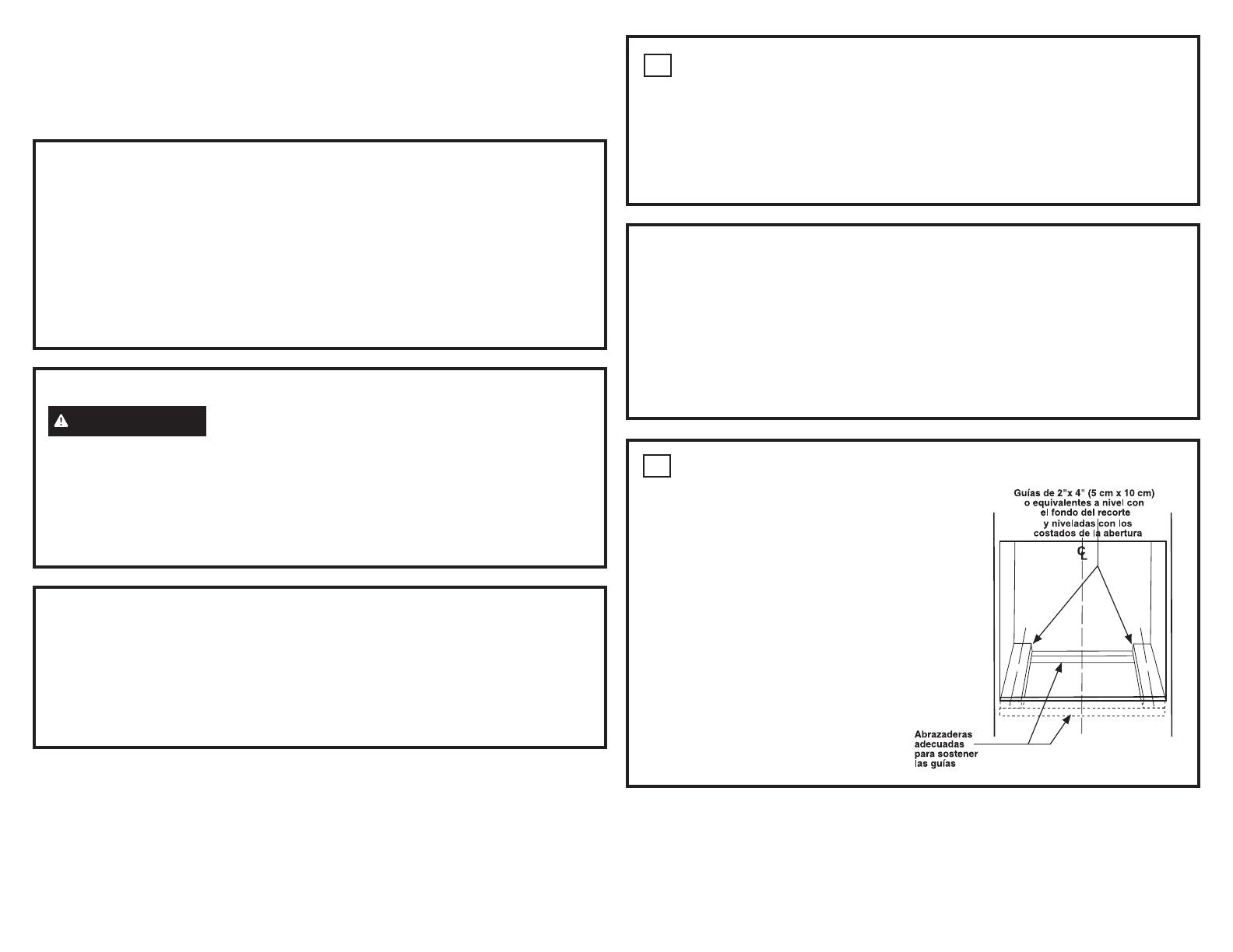
PREPARE LA ABERTURA
NOTA: Si el gabinete no cuenta con un fondo
sólido, deben instalarse dos abrazaderas o guías
para soportar el peso del horno. Para hornos únicos,
las guías o abrazaderas deben soportar 220 lbs (99
kgs). Para hornos dobles y combinados, las guías o
abrazaderas deben soportar 400 lbs (181 kgs).
NOTA: Si marcas, imperfecciones o la abertura
resultaran visibles sobre el horno instalado, es
posible que sea necesario agregar cuñas de madera
debajo de las correderas hasta que las marcas o
aperturas estén cubiertas.
NOTA: Si el gabinete no cuenta con un armazón
frontal y los lados son menores a un grosor de
¾” (1,9 cm), coloque cuñas uniformemente sobre
ambos lados para establecer al ancho de la abertura.
ATENCIÓN INSTALADOR: Todos los hornos de pared eléctricos deben contar con cableado
de conexión permanente (cableado directo) dentro de una caja de conexiones aprobada. En estos productos
NO se permite la conexión del tipo “enchufe y receptáculo”.
INFORMACIÓN DE DISE
INSTALACIONES DE HORNO ÚNICO
El horno único puede instalarse solo en un gabinete o sobre un cajón calentador. El horno único también
puede ser instalado uno al lado del otro, debajo de una mesada, o debajo de superficies de cocción
específicas. Vea la etiqueta de la parte superior del horno para consultar los modelos aprobados.
INSTALACIONES DE HORNOS DOBLES Y COMBINADOS
Un horno doble o combinado puede ser instalado en un gabinete solo o sobre un cajón para calentar
. Vea la
etiqueta de la parte superior del horno para consultar los modelos aprobados.
IMPORTANTE: Siempre consulte las instrucciones de instalaciones individuales enviadas con cada producto
para requerimientos específicos.
Instrucciones de instalación
Hornos de pared eléctricos empotrados de 27” y 30”
¿Preguntas? Comuníquese con nosotros al 1.800.432.273 o visita GEAppliances.com.
En Canadá, llame 1.800.561.3344 o visita GEAppliances.ca.


