Page is loading ...

Air Compressor
Portable/Stationary Gasoline Engine
OPERATOR’S MANUAL
SAFETY
●
ASSEMBLY
●
OPERATION
●
MAINTENANCE
●
STORAGE
●
TROUBLESHOOTING
●
ESPAÑOL
●
FRANÇAIS
D26805 Rev. 0 7/11/02
Read Operator’s Manual. Do not operate equipment until you have read
this Operator’s Manual for Safety, Assembly, Operation, and Mainte-
nance Instructions.
Register your product on line at www.devap.com

2- ENG
D26805
TABLE OF CONTENTS
SAFETY GUIDELINES . . . . . . . . . . . . . . . . . . . . . . . . . . . . . .3-8
ON-RECEIPT INSPECTION . . . . . . . . . . . . . . . . . . . . . . . . . . . .9
GLOSSARY . . . . . . . . . . . . . . . . . . . . . . . . . . . . . . . . . . . . . . . .9
ACCESSORIES . . . . . . . . . . . . . . . . . . . . . . . . . . . . . . . . . . . . .9
ASSEMBLY . . . . . . . . . . . . . . . . . . . . . . . . . . . . . . . . . . . . . . .12
INSTALLATION . . . . . . . . . . . . . . . . . . . . . . . . . . . . . . . . . . . .12
OPERATION . . . . . . . . . . . . . . . . . . . . . . . . . . . . . . . . . . . .13-16
MAINTENANCE . . . . . . . . . . . . . . . . . . . . . . . . . . . . . . . . .17-19
SERVICE AND ADJUSTMENTS . . . . . . . . . . . . . . . . . . . . .19-21
STORAGE . . . . . . . . . . . . . . . . . . . . . . . . . . . . . . . . . . . . . . . .21
TROUBLESHOOTING GUIDE . . . . . . . . . . . . . . . . . . . . . . .22-25
NOTES . . . . . . . . . . . . . . . . . . . . . . . . . . . . . . . . . . . . . . . . . .26
WARRANTY . . . . . . . . . . . . . . . . . . . . . . . . . . . . . . . . . . . . . . .27
ESPAÑOL . . . . . . . . . . . . . . . . . . . . . . . . . . . . . . . . . . . . . .28-52
FRANÇAIS . . . . . . . . . . . . . . . . . . . . . . . . . . . . . . . . . . . . .53-78

3- ENG
D26805
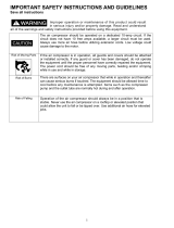
SAFETY GUIDELINES - DEFINITIONS
Indicates an
imminently hazardous
situation which, if not avoided, will
result in death or serious injury.
Indicates a
potentially
hazardous situation which, if not
avoided, could
result in death or
serious injury.
Indicates a
potentially hazardous
situation which, if not avoided, may
result in minor or moderate injury.
Used without the
safety alert symbol
indicates a potentially hazardous
situation which, if not avoided, may
result in pr
operty damage.
This manual contains information that is important for you to know and
understand. This information relates to protecting YOUR SAFETY and
PREVENTING EQUIPMENT PROBLEMS. To help you recognize this
information, we use the symbols below. Please read the manual and pay
attention to these symbols.
IMPORTANT SAFETY INSTRUCTIONS
Some dust created by power sanding, sawing, grinding,
drilling, and other construction activities contains chemicals
known (to the State of California) to cause cancer, birth defects or other
reproductive harm. Some example of these chemicals are:
●
lead from lead-based paints
●
crystalline silica from bricks and cement and other masonry products
●
arsenic and chromium from chemically-treated lumber
Your risk from these exposures varies, depending on how often you do this
type of work. To reduce your exposure to these chemicals: work in a well
ventilated area, and work with approved safety equipment, always wear
MSHA/NIOSH approved, properly fitting face mask or respirator when using
such tools.
When using air tools, basic safety precautions should always be followed to
reduce the risk of of personal injury.
This product is not equipped with a spark arresting muffler. If
the product will be used around flammable materials, or on
land covered with materials such as agricultural crops, forest, brush, grass, or
other similar items, then an approved spark arrester must be installed and is
legally required in the state of California. It is a violation of California statutes
section 130050 and/or sections 4442 and 4443 of the California Public
Resources Code, unless the engine is equipped with a spark arrestor, as
defined in section 4442, and maintained in effective working order. Spark
arresters are also required on some U. S. Forest service land and may also be
legally required under other statutes and ordinances.
This product may contain chemicals known to the state of California to cause
cancer, birth defects, or other reproductive harm. This warning is given in
compliance with California Proposition 65, as detectable amounts of chemicals
subject to proposition 65 may be contained in this product.

4- ENG
D26805
IMPORTANT SAFETY INSTRUCTIONS
Save these instructions
Improper operation or maintenance of this product could result in serious injury and
property damage. Read and understand all warnings and operation instructions before
using this equipment.
HAZARD
WARNING: Risk of explosion or fire
How To Prevent It
What Could Happen
Gasoline and gasoline vapors can
become ignited by coming into contact
with hot components such as the muffler,
from engine exhaust gases, or from an
electrical spark.
Combustible materials which come into
contact with hot engine parts can
become ignited.
Unattended operation of this product
could result in personal injury or
property damage. To reduce the risk of
fire, do not allow the compressor to
operate unattended.
Turn engine off and allow it to cool
before adding fuel to the tank. Equip
area of operation with a fire extinguisher
certified to handle gasoline or fuel fires.
Add fuel outdoors in a well ventilated
area. Make sure there are no sources of
ignition, such as cigarettes near refueling
location.
Operate compressor in a clean, dry, well
ventilated area a minimum of forty-eight
inches from any building, object or wall.
Do not operate unit indoors or in any
confined area.
Operate compressor in an open area
away from dry brush, weeds or other
combustible materials.
Store fuel in a secure location away from
compressor.
Always remain in attendance with the
product when it is operating.

5- ENG
D26805
WARNING: Risk of Bursting
Air Tank: The following conditions could lead to a weakening of the tank, and result
in a violent tank explosion and could cause property damage or serious injury.
How To Prevent It
What Could Happen
HAZARD
Drain tank daily or after each use. If
tank develops a leak, replace it
immediately with a new tank or replace
the entire compressor.
1. Failure to properly drain condensed
water from tank, causing rust and
thinning of the steel tank.
2. Modifications or attempted repairs
to the tank.
Never drill into, weld, or make any
modifications to the tank or its
attachments. Never attempt to repair a
damaged or leaking tank. Replace with a
new tank.
4. Excessive vibration can weaken
the air tank and cause rupture or
explosion. Excessive vibration will
occur if the compressor is not
properly mounted or if engine
operates above recommended RPM.
The tank is designed to withstand specific
operating pressures. Never make
adjustments or parts substitutions to
alter the factory set operating
pressures.
For essential control of air pressure, you
must install a pressure regulator and
pressure gauge to the air outlet (if not
equipped) of your compressor. Follow the
equipment manufacturers recommendation
and never exceed the maximum allowable
pressure rating of attachments. Never use
compressor to inflate small low pressure
objects such as children’s toys, footballs,
basketballs, etc.
A
TTACHMENTS & ACCESSORIES:
Exceeding the pressure rating of air
tools, spray guns, air operated
accessories, tires, and other inflatables
can cause them to explode or fly apart,
and could result in serious injury.
3. Unauthorized modifications to the
unloader valve, safety valve, or any
other components which control
tank pressure.
Do not remove the stiffener bar
connecting the compressor pump to the
engine, except to adjust belt tension,
Then securely tighten the stiffener bar
nuts. This bar controls unit vibration.

6- ENG
D26805
HOW TO PREVENT IT
WHAT CAN HAPPEN
WARNING: Risk to Breathing
HAZARD
The compressed air directly from your
compressor is not safe for breathing.
The air stream may contain carbon
monoxide, toxic vapors, or solid
particles from the tank. Breathing these
contaminant's can cause serious injury
or death.
Sprayed materials such as paint, paint
solvents, paint remover, insecticides,
weed killers, may contain harmful vapors
and poisons.
Air obtained directly from the compressor
should never be used to supply air for
human consumption. In order to use air
produced by this compressor for
breathing, suitable filters and in-line
safety equipment must be properly
installed. In-line filters and safety
equipment used in conjunction with the
compressor must be capable of treating
air to all applicable local and federal
codes prior to human consumption.
Work in an area with good cross
ventilation. Read and follow the safety
instructions provided on the label or
safety data sheets for the materials you
are spraying. Use a NIOSH/ MSHA
approved respirator designed for use
with your specific application.
WARNING: Risk from Flying Objects
HOW TO PREVENT IT
WHAT CAN HAPPEN
The compressed air stream can cause
soft tissue damage to exposed skin and
can propel dirt, chips, loose particles,
and small objects at high speed,
resulting in property damage or personal
injury.
Always wear ANSI Z87.1 approved safety
glasses with side shields when using the
compressor.
Never point any nozzle or sprayer
toward any part of the body or at other
people or animals.
Always turn the compressor off and
bleed pressure from the air hose and tank
before attempting maintenance, attaching
tools or accessories.
HAZARD
Breathing exhaust fumes from engines
will cause serious injury or death.
Always operate air compressor outside
in a clean, well ventilated area. Avoid
enclosed areas such as garages,
basements, storage sheds, which lack a
steady exchange or air. Keep children,
pets and others away from area of
operation.

7- ENG
D26805
HOW TO PREVENT IT
WHAT CAN HAPPEN
WARNING: Risk of Burns
Touching exposed metal such as the
compressor head, engine head, exhaust
or outlet tubes, can result in serious
burns.
Never touch any exposed metal parts
on compressor during or immediately
after operation. Compressor will remain
hot for several minutes after operation.
Do not reach around protective shrouds
or attempt maintenance until unit has
been allowed to cool.
HOW TO PREVENT IT
WHAT CAN HAPPEN
WARNING: Risk from Moving Parts
Never operate the compressor with
guards or covers which are damaged or
removed.
Moving parts such as the pulley, flywheel,
and belt can cause serious injury if they
come into contact with you or your
clothing.
HAZARD
HAZARD
Any repairs required on this product
should be performed by authorized
service center personnel.
Attempting to operate compressor with
damaged or missing parts or attempting
to repair compressor with protective
shrouds removed can expose you to
moving parts and can result in serious
injury.
Always disconnect the spark plug and
bleed pressure from the tank before
performing maintenance.
The engine can start accidentally if the
flywheel is turned by hand or moved by
pulling on the starter rope.
HOW TO PREVENT IT
WHAT CAN HAPPEN
WARNING: Risking of Falling
A portable compressor can fall from a
table, workbench or proof causing
damage to the compressor and could
result in serious injury or death to the
operator.
Always operate compressor in a stable
secure position to prevent accidental
movement of the unit. Never operate
compressor on a roof or other elevated
position. Use additional air hose to
reach high locations.
HAZARD

8- ENG
D26805
HOW TO PREVENT IT
WHAT CAN HAPPEN
WARNING: Risk of Unsafe Operation
Review and understand all instructions
and warnings in this manual.
Become familiar with the operation and
controls of the air compressor.
Keep operating area clear of all persons,
pets, and obstacles.
Keep children away from the air
compressor at all times.
Do not operate the product when
fatigued or under the influence of
alcohol or drugs. Stay alert at all times.
Never defeat the safety features of this
product.
Equip area of operation with a fire
extinguisher.
Do not operate machine with missing,
broken, or unauthorized parts.
Unsafe operation of your air compressor
could lead to serious injury or death to
you or others.
HAZARD
HOW TO PREVENT IT
WHAT CAN HAPPEN
Oil can leak or spill and could result in
fire or breathing hazard; serious injury or
death can result. Oil leaks will damage
carpet, paint or other surfaces in vehicles
or trailers.
Always place compressor on a
protective mat when transporting to
protect against damage to vehicle from
leaks. Remove compressor from vehicle
immediately upon arrival at your
destination. Never lie compressor on its
side.
(Fire, Inhalation, Damage to Vehicle Surfaces)
HAZARD
WARNING: Risk of Serious Injury or Property Damage when
Transporting Compressor

9- ENG
D26805
GLOSSARY
Become familiar with these terms before operating the unit.
CFM: Cubic feet per minute.
SCFM: Standard cubic feet per minute; a unit of measure of air delivery.
PSIG: Pounds per square inch gauge; a unit of measure of pressure.
Code Certification: Products that bear one or more of the following marks:
UL, CUL, ETL, CETL, have been evaluated by OSHA certified independent
safety laboratories and meet the applicable Underwriters Laboratories
Standards for Safety.
Unloader Blow-Off Pressure: All models are continuous running units
controlled by tank pressure. When the maximum tank pressure is obtained, the
unloader valve will blow-off. This will cause the compressor to exhaust the air
to the atmosphere and not the tank. This decreases the load on the engine and
allows it to run at a near no-load condition.
Unloader Reset Pressure: When the tank pressure drops to a predetermined
point, the unloader valve closes. The tank pressure will now increase until it
reaches the unloader blow-off pressure.
ON-RECEIPT INSPECTION
Each air compressor outfit is carefully checked before shipment. With improper
handling, damage may result in transit and cause problems in air compressor
operation.
Immediately upon arrival, check equipment for both concealed and visible
damages to avoid expenses being incurred to correct such problems. This
should be done regardless of any visible signs of damage to the shipping
container.
Report any damages to carrier and arrange for inspection of goods
immediately.
For the location or a listing of the nearest Authorized Warranty Service Center,
call our toll free number at 1-800-888-2468, Ext. 2.
Accessories for this unit are available at the store the unit was purchased.
ACCESSORIES
ASSEMBLY
Contents of Carton
1 - Air Compressor
1 - Thread Sealant Tape
1 - Screw .250-20 .625 Set Square
1 - Shut-off Valve 1/4" NPT
1 - Engine Manual
1 - Owner's Manual
1 - Parts Manual
4 - Vibration Mount
8 - Lock Washer
4 - Flat Washer
Tools Required for Assembly
1 - a 9/16" socket or open-end wrench for attaching the wheels
1 - a 7/16" open-end wrench for attaching the rubber feet
1 - a 1/4" open-end wrench for attaching the shut-off valve and air outlet adapter.
8 - Hex Nut .313-18 UNC
2 - Cap Screw
2 - Hex Nut .250-20 UNC
2 - Hex Nut .375-16 UNC
2 - Rubber Feet
2 - Shoulder Bolt
2 - Lock Washer
1 - Handle
2 - Wheel

10- ENG
D26805
Unpacking
1. Remove unit from carton and discard all packaging. NOTE: Save all parts
bags.
The wheels and handle do not provide adequate
clearance, stability or support for pulling the unit up and
down stairs or steps. The unit must be lifted, or pushed up a ramp.
Installing Handle
Do not use the engine gas tank as a support for lifting the
air compressor.
1. Insert the handle into pockets under the tank saddle. Put one set screw
through hole in one side of tank saddle and tighten down on handle.
Assemble Wheels and Rubber Feet for Portability
Excessive tank vibration can weaken the air tank and
cause rupture or explosion. Rubber feet must be installed.
It will be necessary to brace or support one side of the
unit when installing the wheels because the compressor
will have a tendency to tip.
1. Attach the rubber feet to the bottom of the air tank bracket as shown.
2. Attach wheels with shoulder bolts and nuts as shown. Place the bolts in
the top hole of the wheel bracket on unit.
3. Tighten securely. NOTE: The unit will sit level if the wheels are properly
installed.
Handle
Set Screw
Tank Saddle
Shoulder Bolt
Wheel
Hex Nut
Handle
Set Screw
Tank Saddle
Hex Nut
Rubber Foot
Cap Screw

11- ENG
D26805
Assemble Shut-Off Valve
1. Apply pipe sealant to the tapered pipe
threads on the shut-off valve and
tighten into the manifold.
Permanent Installation
Bolting legs to a stiff surface can cause tank rupture
resulting in serious injury or damage. Do not permanently
mount compressor to any surface without using the vibration mount kit.
This compressor may be permanently mounted in a location such as a truck
bed, it desired. A vibration mount kit is included for this purpose.
1. In order to maintain adequate ventilation for compressor cooling and to
avoid contact with pick-up truck bed, always mount the unit at least 8"
from any vertical wall. Using the holes in the air tank legs as a guide, mark
and drill four 5/16" diameter holes in the mounting surface.
2. Insert the vibration mounts in the mounting holes. Place a flat washer
under the mounting surface and secure each mount with a lock washer
and nut.
3. Set the unit on the exposed threaded
ends of the mount to the air tank legs with
a lock washer and nut.
Lubrication and Oil
Engine
1. The engine was filled WITH
oil at the manufacturer. Check engine oil level
before operating unit. If necessary, fill engine to the appropriate level with
recommended oil, see engine manual supplied by engine manufacturer for
correct procedure.
2. Add fuel to engine. See engine manual supplied by engine manufacturer for
correct procedure.
Gasoline vapor is highly flammable. Refuel outdoors
preferably, or only in well-ventilated areas. Do not refuel or
check gasoline level while the engine is running. Do not store, spill, or use
gasoline near an open flame, a source of sparks (such as welding), or near
operating electrical equipment.
shut-off valve
manifold

12- ENG
D26805
INSTALLATION
Location of the Air Compressor
Exhaust from the gasoline engine contains deadly carbon
monoxide, which is odorless and toxic. Operate engine
only in well ventilated areas.
The air compressor must be operated in a clean, dry, and well-ventilated area.
The air compressor's crankcase and head are designed with cooling fins to
provide proper cooling. The fan blades of the compressor, the flywheel, must be
kept clear of obstructions that could interfere with the flow of air through the air
intake filter.
Do not install the air compressor in a location where heat is excessive. If
the humidity in the operating area is high, an air filter can be installed on the air
outlet adapter to remove excessive moisture. This type air filter is not provided
with this air compressor and must be purchased separately. Closely follow the
instructions packaged with the filter for proper installation.
Do not allow the air compressor to get wet if it is installed
outdoors.
Piping
Plastic or PVC pipe is not designed for use with
compressed air. Regardless of its indicated pressure
rating, plastic pipe can burst from air pressure. use only metal pipe for air
distribution.
If a pipe line is necessary, use pipe that is the same size as the air tank outlet.
Piping that is too small will restrict the flow of air. If piping is over 100 feet long,
use the next larger size. Bury underground lines below the frost line and avoid
pockets where condensation can gather and freeze. Apply pressure to lines
before underground lines are buried to make sure all pipe joints are free of leaks.
Air Compressor
The air compressor pump was filled WITH oil at the manufacturer. Check air
compressor pump oil level before operating unit. If necessary, fill pump to the
appropriate level with approved compressor oil, see the Maintenance section of
this manual for details.

13- ENG
D26805
OPERATION
Know Your Air Compressor
READ THIS OWNER’S MANUAL AND SAFETY RULES BEFORE OPERATING
YOUR UNIT. Compare the illustrations with your unit to familiarize yourself with
the location of various controls and adjustments. Save this manual for future
reference.
Description of Operation
Become familiar with these controls before operating the unit.
Air Compressor Pump (not shown): To compress air, the pistons move up
and down in the cylinders. On the downstroke, air is drawn in through the air
intake filter and then through the air intake valves. The exhaust valve remains
closed. On the upstroke of the piston, air is compressed. The intake valves
close and compressed air is forced out through the exhaust valve, through the
outlet tube, through the check valve and into the air tank. Working air is not
available until the compressor has raised air tank pressure above that required
at the air outlet.
Throttle Control (not shown): A throttle control has been incorporated as an
extra feature. When maximum tank pressure is reached and the unloader valve
unloads air, it also activates a throttle control on the engine. This gas saving
feature holds the engine at a factory-set idling speed until air pressure in the air
tank drops to reset pressure; it then reactivates the throttle control and
accelerates the engine to full throttle.
Tank Pressure Gauge: The tank pressure gauge indicates
the reserve air pressure in the tank.
Unloader Valve: All models are continuous running
outfits controlled by tank pressure. When the
maximum tank pressure is obtained, the unloader
valve will exhaust the compressed air to the
atmosphere (blow-off). When the pressure drops to a
predetermined point, the unloader valve closes and
causes the tank pressure to increase.
Safety Valve: If the unloader valve does not shut off the
air compressor at or near its cut-out pressure setting,
the safety valve will protect against high pressure by
"popping out" at its factory set pressure (slightly higher
than the unloader blow-off setting).
Tank
Pressure
Gauge
Safety
Valve
Unloader Valve

14- ENG
D26805
Shut Off Valve: Opens and closes air flow.
Drain Valve: The drain valve is located at the base
of the air tank and is used to drain condensation
at the end of each use.
Air Intake Filter (not shown): This filter is
designed to clean air coming into the pump. This
filter must always be clean and ventilation
openings free from obstructions. See
"Maintenance".
Engine Stop Lever: Used to stop engine. Push down
and hold until engine shuts off.
Shut-off
Valve
Drain
Valve
Engine
Stop Lever
How to Use Your Unit
How to Stop:
1. See the engine manufacturer's manual for the procedure to safely shut
down the gasoline engine. Turning the gasoline engine off will turn off the air
compressor as well.
Before First Start-up
Break-in Procedure
Serious damage may result if the following break-in
instructions are not closely followed.
This procedure is required when:
1. Before the air compressor is used for the first time.
2. When the unloader valve is
replaced.
3. When a complete compressor pump is replaced.
The procedure:
1. To prevent pressure from building up in the air
tanks during this break-in period, you must
open the unit's unloader valve. Place unloader
valve in “Open” position as shown.
Open

15- ENG
D26805
2. Turn shut-off valve knob into open position.
3. Start engine. See engine manual supplied by
engine manufacturer for correct procedure.
The air compressor is top heavy.
Make sure the unit is in a stable
position and will not tip before pulling the starter
cord of the engine.
4. Make sure the unloader valve is in the “Open”
position to prevent tank pressure buildup.
5. Run the air compressor for 30 minutes to seat the rings and lubricate all
the internal surfaces. Make sure there is no pressure build up in the tank by
observing the reading on the tank pressure gauge.
6. Place unloader valve in the “Closed” position as
shown.
7. Close the shut-off valve knob. This will allow air to
build pressure in the air tanks.
NOTE: When the air tank is pressurized, the tank pressure gauge will indicate
the pressure available in the air tank and the gasoline engine will reduce its
speed to idle and keep running. The pressurization of the air tank will be
adjusted automatically by the "reset" and "blow off" setting of the unloader
valve. When the pressure in the air tank drops to the "reset" value, the gasoline
engine will increase its rpm to operate the compressor and pressurize the
tanks. When the pressure in the air tank increases to the "blow off" value, the
engine rpm will drop to idle.
NOTE: Consult the engine manufacturer's manual for the proper engine
break-in running time and oil change interval for the engine used on your
air compressor as well as other engine maintenance requirements.
8. Compressed air will be available from the unit's outlet valve until it is used
up or bled off. The compressor is now ready for use.
Before each start-up
Perform the following checks before starting the air compressor.
1. Make sure nothing is blocking the belt guard, air openings, or air filter inlet.
2. Make sure the unloader valve moves freely and smoothly.
3. Check the oil level in the pump and engine, add oil if necessary.
Temperature of muffler and near by areas my exceed
150°F (65°C) avoid these areas.
open
postion
Closed
closed
postion

16- ENG
D26805
To start-up
6. Start the engine (see engine manual supplied by engine manufacturer for
correct procedure) and close unloader to allow tank pressure to pump up to
blow-off pressure.
Unit is top heavy. Make sure the compressor is stable and
will not tip before pulling the starting cord.
Too much air pressure causes a hazardous risk of
bursting. Closely monitor the air pressure gauge of the
tank so the maximum pressure limit is not exceeded and monitor the
safety valve to ensure excess pressure is discharged. If pressure
continues to build beyond safe limits, shut the unit down immediately and
troubleshoot the problem.
7. Check all fittings and piping for air leaks. Even minor leaks can cause the
air compressor to overwork, resulting in premature breakdown or
unsatisfactory performance.
8. Check for any unusual vibration and noise.
9. Check for oil leaks and correct any leaks found.
10. Check the pressure ratings of the air tools and accessories being used with
this air compressor before attaching, then adjust the shut-off valve for that
value.
The air compressor's outlet pressure must never exceed
the maximum pressure rating of the tool or accessory
being used. If a pressure regulator is not used, do not use accessories
rated at less than 110 psi.
11. Attach air hose and accessory. Your unit is ready for use.
Compressed air from the unit may contain water
condensation and oil mist. Do not spray unfiltered air at an
item that could be damaged by moisture. Some air operated tools or de-
vices may require filtered air. Read the instructions for the air tool or
device.
Shutting Down
12. Push down engine stop lever and hold until engine shuts off.
13. Close shut-off valve.
14. Remove the air tool or accessory.
15. Open shut-off valve and allow air to slowly bleed from the tank. Close the
shut-off valve or when the tank pressure is approximately 20 PSIG.
Drain air tank daily. Water will condense in air tank. If not
drained, water will corrode and weaken the air tank
causing a risk of tank rupture.
16. With tank pressure at approximately 20 PSIG, open the drain valves and
allow moisture to drain.
NOTE: If drain cock is clogged, release all air pressure. The drain cock can
then be removed, cleaned, and reinstalled.
17. After the water has been drained, close the drain cocks. The air compressor
can now be stored.
4. Clean or blow off fins or any part of the air compressor that collects dust
and dirt. The air compressor will run cooler and provide longer service.
5. Open the unloader valve of the air compressor before starting the engine.

17- ENG
D26805
MAINTENANCE
Customer Responsibilities
Daily or
after
each
use
Before
each
use
●
●
●
●
Every
8
hours
Every
40
hours
Every
100
hours
Yearly
Every
160
hours
●
●
1
1- more frequent in dusty or humid conditions
Check Safety Valve
Drain Tank
Oil Leaks
Check Pump Oil
Change Pump Oil
Air Filter
NOTE: See "Operation"section for the location of controls.
To ensure efficient operation and longer life of the air compressor outfit, a
routine maintenance schedule should be prepared and followed. The following
routine maintenance schedule is geared to an outfit in a normal working
environment operating on a daily basis. If necessary, the schedule should be
modified to suit the conditions under which your compressor is used. The
modifications will depend upon the hours of operation and the working
environment. Compressor units in an extremely dirty and/or hostile environment
will require a greater frequency of all maintenance checks.
During maintenance, you could be exposed to compressed
air or moving parts. Personal injuries can occur. Before
doing any maintenance or repair, disconnect the spark plug wire to prevent
accidental starting, and relieve air tank pressure. Never operate the
compressor with the belt guard removed.
To Check Safety Valve
If the safety valve does not work properly, over-
pressurization may occur, causing air tank rupture or an
explosion.
1. Before starting compressor, pull the ring on the safety valve to make sure
that the safety valve operates freely. If the valve is stuck or does not
operate smoothly, it must be replaced with the same type of valve.
●
●
●
●
Drive Belt -Condition
Motor Pulley/Flywheel alignment
Air compressor pump intake
and exhaust valves
Unusual Noise and/or Vibration
Consult the Engine Owners Manual for the manufacturer's recommendations
for any and all engine maintenance.

18- ENG
D26805
Air Filter - Inspection and Replacement
Hot surfaces. Risk of burn. Compressor heads are
exposed when filter cover is removed. Allow compressor
to cool prior to servicing.
Keep the air filter clean at all times. Do not operate the air
compressor with the air filter removed.
A dirty air filter will not allow the compressor pump to operate at full
capacity. Before using the compressor pump, check the air filter to make
sure it is clean and in place.
Oil
Drain tank to release air pressure before removing the oil
fill cap or oil drain plug.
Checking
1. Remove the oil fill plug (A). The oil level should be even
with the top of the fill hole and no lower than 6 threads
from the top of fill hole.
2. If needed, slowly add oil until it reaches the top of fill hole.
NOTE: Use an oil specifically formulated for use in an air
compressor, such as Sears 9-16426 air compressor oil.
Changing
1. Remove the oil fill plug (A).
2. Remove the oil drain plug (B) and drain oil into a suitable container.
3. Replace the oil drain plug (B) and tighten securely
4. Slowly fill crankcase to the top of the fill hole. Crankcase capacity is 16
fluid ounces (473.2 ml).
A
B
To Drain Tank
1. Push down and hold engine stop lever until engine shuts off.
2. Remove the air tool or accessory.
3. Pull ring on safety valve allowing air to bleed from the tank until tank
pressure is approximately 20 psi. Release safety valve ring.
4. Drain water from air tank by opening drain valve (counter-clockwise) on
bottom of tank.
Water will condense in the air tank. If not drained, water
will corrode and weaken the air tank causing a risk of air
tank rupture.
5. After the water has been drained, close the drain valve (clockwise). The air
compressor can now be stored.
NOTE: If drain valve is plugged, release all air pressure. The valve can then be
removed, cleaned, then reinstalled.
Overfilling with oil will cause premature compressor
failure. Do not overfill.
5. Replace oil fill plug (A) and tighten securely.

19- ENG
D26805
If it is dirty, replace it with a new filter.
1. Using a pair of needle nose pliers or a screwdriver pull or
pry out the old filter and carefully clean the filter area.
2. Push the new air filter in place. Refer to the "Repair Parts"
for the correct part number.
IMPORTANT: Do not operate the compressor with the air filter removed.
Safety Valve-Replacement
If the safety valve does not work properly, over-
pressurization can occur and cause air tank rupture or
explosion. Daily pull the ring on the safety valve and make sure it operates
freely. If the valve is stuck or does not operate smoothly, it must be
replaced with the same type of valve having an identical pressure rating.
To Remove Safety Valve:
1. Make sure the air compressor unit is off and
disconnect the spark plug wire.
2. Open the shut-off valve and allow all air to bleed
from the tank. Monitor tank pressure gauge as
tank is emptied.
3. When tank is empty, remove safety valve (A) from
manifold.
To Install New Safety Valve:
1. Verify new safety valve is the correct pressure rating
for your air compressor.
2. Verify threads for safety valve in manifold are clean.
3. Apply thread sealant to the threads of new safety valve.
4. Install new safety valve and tighten securely.
5. Reconnect spark plug wire to engine.
Air Compressor Pump Intake and Exhaust Valves
Once a year have a Trained Service Technician check the air compressor pump
intake and exhaust valves.
SERVICE AND ADJUSTMENTS
ALL MAINTENANCE AND REPAIR OPERATIONS NOT LISTED MUST BE
PERFORMED BY TRAINED SERVICE TECHNICIAN.
Before servicing:
• Stop engine.
• Bleed tank of pressure.
• Allow the air compressor to cool.
A

20- ENG
D26805
Belt – Replacement and Adjustment
Serious injury or damage may occur if parts of the body or
loose items get caught in moving parts. Never operate the
unit with the belt guard removed. the belt guard should be removed only
when the air compressor is turned off the spark plug wire is disconnected.
Belt Guard – Removal
1. Disconnect the spark plug wire on the engine and release all air tank
pressure.
2. (Refer to figure) Remove the four screws
(A) from the belt guard. The belt guard
can now be removed.
Belt – Replacement
1. Disconnect the spark plug wire on the
engine and release all air tank pressure.
2. Remove the belt guard as previously
described.
3. Mark engine position on saddle.
4. Loosen stiffener bracket screws on engine.
5. (Refer to Figure) Being careful not to remove
the stiffener plate under the saddle, loosen
the six engine mounting bolts (C).
6. Slide engine toward pump to remove
tension from the belt, and then remove the
old belt.
7. Install the new belt over the pulleys.
NOTE: The belt must be centered over the
grooves on the engine pulley and flywheel.
8. Slide the engine back into its regular position. Line the engine up with the
mark made earlier on saddle.
Belt Tension - Adjustment
1. Hold belt tension and securely tighten two engine mounting bolts.
2. Measure correct belt tension. Proper tension is achieved when a three (3)
pound weight or equivalent finger pressure applied midway between the
motor pulley and compressor flywheel causes a 1/4" deflection of the belt
as shown.
3. When proper belt tension is achieved,
tighten the remaining engine mounting
bolts.
4. Tighten stiffener bracket screws.
NOTE: Once the engine pulley has been
moved from its factory set location, the
grooves of the flywheel and pulley must
be aligned to within 1/16" to prevent
excessive belt wear. Verify the alignment
by performing the following Pulley and
Flywheel - Alignment.
5. Replace belt guard.
A
C
/