Page is loading ...

INSTALLATION, OPERATION,
MAINTENANCE, AND PARTS LIST
SERIES I
MILLING MACHINES
Revised: March 21, 2018
Manual No. M-508 Litho in U.S.A.
Part No. M -0009500-0508 June, 2010
TP8035A

Information in this manual is subject to change without notice.
This manual covers installation, operation, maintenance, and parts list for
Bridgeport Series I milling machines with serial numbers ending with the let-
ter "M". The machine serial number is located on the front of the knee. If the
machine serial number does not end with the letter "M", refer to the latest
version of manual M -0009500-0450.
In no event will Hardinge Inc. be responsible for indirect or consequential
damage resulting from the use or application of the information in this man-
ual.
Reproduction of this manual, in whole or in part, without written permis-
sion of Hardinge Inc. is prohibited.
ORDERING REPLACEMENT PARTS
Please provide the following information when ordering replacement parts:
1. The complete machine serial number. The machine serial number is located on the front of the
knee.
2. List the following:
A) Manual Number (M-508).
B) Page Number.
C) Item Number.
D) Part Description.
E) Part Number.
F) Quantity of each part required.
3. Specify how and where to ship.
- NOTE -
Bridgeport is a registered trademark of Hardinge Inc.
© 2010, Hardinge Inc. M-508

SAFETY PRECAUTIONS
To prevent serious bodily injury, observe the following basic safety precautions when installing,
operating or servicing the milling machine.
1. Follow all instructions in the manual.
2. Wear approved industrial safety glasses and safety shoes.
3. Do not wear gloves, long sleeves, long hair, rings, watches, jewelry or other items that could
become caught in moving parts.
4. Keep all parts of your body away from moving parts (belts, cutters, gears, etc.)
5. Use proper point of operation safeguarding.
These and other safety precautions are discussed in the American National Standard Institute
standard entitled Safety Requirements for Manual Milling, Drilling and Boring Machines with or
without Automatic Control (ANSI B11.8-2001).
This publication is available from:
American National Standards Institute
25 West 43rd Street, 4th floor
New York, NY 10036
To assist machine users in designing point of operation safeguarding for their specific machine
applications, the Occupational Safety And Health Administration has published a booklet entitled
Concepts and Techniques of Machine Safeguarding (OSHA Publication No. 3067).
This publication is available from:
U.S. Department of Labor
OSHA Publications Office
200 Constitution Avenue, NW
Room N3315
Washington, D.C. 20210
The general purpose point of operation shield provided with this machine and shown in certain
illustrations throughout this manual may not be appropriate and cannot be utilized for all possible
applications of the machine. Use additional or alternate safeguarding where this shield is not
appropriate or cannot be utilized. Note that for purposes of display, the shield has been removed in
certain other illustrations in this manual.
CALIFORNIA PROPOSITION 65 WARNING
WARNING: California Residents
Product can expose you to chemicals including one or more listed chemicals which
are known to the State of California to cause cancer or birth defects or other repro-
ductive harm. For more information, go to www.P65Warnings.ca.gov
M-508 i

CONVENTIONS USED IN MANUALS
DANGER
DANGER indicates a hazardous situation that, if not avoided, will result in death or
serious injury.
WARNING
WARNING indicates a hazardous situation that, if not avoided, could result in death
or serious injury.
CAUTION
CAUTION indicates a hazardous situation that, if not avoided, could result in minor
or moderate injury.
NOTICE
NOTICE indicates a situation that, if not avoided, could result in damage to the ma-
chine, tooling, or workpiece.
- NOTES -
Notes contain supplemental information.
ii M-508

SAFETY RECOMMENDATIONS
DO NOT OPERATE EQUIPMENT until you have read and understood the appropriate opera-
tor and safety maintenance manuals.
DO NOT OPERATE EQUIPMENT until you have read and understood all machine and con-
trol key signs.
DO NOT OPERATE EQUIPMENT for the first time without a qualified instructor. Consult your
supervisor when in doubt as to the correct way to perform an operation.
DO NOT OPERATE EQUIPMENT unless proper maintenance has been regularly performed
and the equipment is known to be in good working order.
DO NOT ALLOW the operation or repair of equipment by untrained personnel.
WARNING or INSTRUCTION TAGS are mounted on the equipment for your safety and infor-
mation. Do not remove them.
DO NOT OPERATE EQUIPMENT if any unusual or excessive heat, noise, smoke, or vibra-
tion occurs. Report any excessive or unusual vibration, sounds, smoke, or heat as well as any
damaged parts.
WEAR SAFETY GLASSES with side shields and SAFETY SHOES with steel toes and oil-re-
sistant soles at all times. When necessary, wear respirator, helmet, and ear muffs or plugs.
DO NOT OPERATE ANY MACHINE while wearing rings, watches, jewelry, loose clothing,
neckties, or long hair not contained by a net or shop cap.
DO NOT WEAR GLOVES while operating equipment. Gloves are easily caught in moving
parts.
REMOVE ANY LOOSE PARTS OR TOOLS left on machine or in the work area before oper-
ating the machine. Always check the machine and work area for loose tools and parts, espe-
cially after work has been completed by maintenance personnel.
REMOVE CHUCK WRENCHES before starting the machine.
NEVER OPERATE A MACHINE after taking strong medication, using non-prescription drugs
or consuming alcoholic beverages.
SAFEGUARD THE CUTTING ZONE (“point of operation”). Use standard, general purpose
safeguards when possible. Use special safeguards when required.
PROTECT YOUR HANDS. Stop the spindle completely before changing tools.
PROTECT YOUR HANDS. Stop the spindle completely before loading or unloading a
workpiece.
DO NOT REMOVE CHIPS with hands. Use a hook or similar device and make certain that all
machine movements have ceased.
DO NOT ADJUST tooling, workpieces or coolant hoses while the machine is running.
PROTECT YOUR HANDS. Stop the spindle completely before taking measurements.
M-508 iii

PROTECT YOUR HANDS. Stop the spindle completely before opening safeguards or covers.
NEVER REACH around a safeguard.
PROTECT YOUR HANDS. Stop the machine before changing or adjusting belts, pulleys or
gears.
PROTECT YOUR HANDS. Keep hands and arms clear of spindle start switch when changing
tools.
PROTECT YOUR EYES AND THE MACHINE. Never use a compressed air hose to remove
chips.
KEEP WORK AREA WELL LIGHTED. ask for additional light if needed.
DON’T SLIP. Keep your work area clean and dry. Remove chips, oil and obstacles.
NEVER LEAN ON your machine. Stand away when the machine is running.
MAKE CERTAIN that you are clear of any “pinch points” created by moving slides before
starting the machine.
PREVENT OBJECTS from flying loose. Securely clamp and locate workpiece. Use stop
blocks where necessary. Keep clamps clear of cutter path.
PREVENT CUTTER BREAKAGE. Use correct table feed and spindle speed for the job. Re-
duce feed and speed if you notice unusual noise or vibration.
PREVENT CUTTER BREAKAGE. Rotate spindle in clockwise direction for right-hand tools,
counterclockwise for left-hand tools. Use the correct tool for the job.
PREVENT WORKPIECE and cutter damage. Never start the machine when the cutter is in
contact with the workpiece.
DO NOT USE worn or defective tools. Use the proper size and type of tool for the task at
hand.
KEEP ROTATING CRANKS AND HANDWHEELS well lubricated and maintained. Do not re-
move safety springs.
CERTAIN MATERIALS, such as magnesium, are highly flammable in dust and chip form. See
your supervisor before working with these materials.
PREVENT FIRE. Keep flammable liquids and materials away from work area and hot chips.
PREVENT MACHINE from moving unexpectedly. Disengage power feed when not being used
(manual machines only).
PREVENT MACHINE from moving unexpectedly. Always start machine in manual mode.
UNLESS OTHERWISE NOTED, all operating and maintenance procedures are to be per-
formed by one person. To avoid injury to yourself and others, be sure that all personnel are
clear of the machine when opening or closing the coolant guard door and any access covers.
iv M-508

INSTALLATION AND USE OF SAFEGUARDS
Both American National Standard B11.8 and OSHA Section 1910.212 assign responsibility for
point of operation safeguarding of milling machines to the employer/user. Therefore, to prevent
serious injury resulting from the rotating cutter, flying chips, or splashing coolant, point of operation
safeguarding should be used on milling machines to the greatest extent practicable.
This booklet provides basic information for the installation and use of the general purpose
safeguard. It also contains the names of several manufacturers of other types of point of operation
safeguarding for vertical milling machines.
Remember, point of operation safeguarding is your responsibility as the employer/user. You are in
the best position to evaluate your safeguarding needs and ensure that the proper safeguards are
installed and used.
WARNING
This safeguard DOES NOT take the place of any other safety practice or safety
equipment.
YOU MUST ALWAYS wear safety glasses and safety shoes.
YOU MUST ALWAYS stop the spindle of the machine completely before changing
or adjusting the workpiece, fixture, or tool.
YOU MUST NEVER wear gloves, long sleeves, long hair, rings, watches, neckties,
jewelry or other loose items.
CAUTION
A safety shield is supplied for protection from chips and coolant with every ma-
chine.
The chip and coolant shields have been designed and are custom manufactured
with the highest clear impact material commercially available: polycarbonate (G.E.
Lexan). It has an impact strength 5 to 10 times greater than acrylic (plexiglass) or
butyrate (UVEX) materials, thereby offering the greatest protection for our custom-
ers.
Some of the new “easy to dispose of” coolants and/or cutting oils contain chemi-
cals harmful to polycarbonate. These chemicals are: Mono-ethanolamine,
Di-ethanolamine, Tri-ethanolamine and the combination thereof. These chemicals
may significantly reduce the impact strength of the shield within days, and could
destroy the entire shield in weeks.
Use of use of coolants and/or cutting oils containing these chemicals will void the
warranty on your safety shield, and could cause injury to your workers.
M-508 v

GENERAL PURPOSE SAFEGUARDS
There is no single safeguard which can match the versatility of the Series I machine. As a result,
you will find that the guard assembles shown in Figures I.I and I.II, like all safeguards, will be suitable
for some operations, but not for others. Carefully analyze the operation to be performed before
deciding whether this safeguard is suitable. Adjust the safeguard to suit your special requirements. If
you find that it is not suitable for a particular application, you should use an alternate form of
protection.
Installation for Machines with R-8 Spindle Taper
There are two tapped holes in the nose cap of the spindle to be used for mounting the guard (the
two untapped holes serve to remove the nose cap with a spanner wrench).
1. Place the mounting ring (Item 11) underneath the top of the guard (Item 7).
2. Place two socket head cap screws (Item 12) through the holes in the ring, and hand-start them
into the threaded holes in the nose cap until hand tight.
3. Align guard to be square with table of machine (unless angular mounting is desired).
4. Tighten screws with a hex Allen wrench.
vi M-508
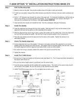
Figure I.I - Spindle Guard Assembly
(R8 Spindle)
11
9
1
10
6
2
12
7
8
TP5262A
3,4,5

Installation for Machines with Erickson 30 Quick Change Spindles
1. Remove the spindle locknut. This is done by removing the long button head black finish screw,
which is normally left of the cadmium-finished button head screw on the locknut of the spindle.
This will allow you to unscrew the locknut by turning it counter-clockwise.
2. Place the nose cap mounting ring “O” up against the quill nose cap and install the four button
head cap screws “M”.
- NOTE -
The counterbored side of the nose cap mounting ring fits against the nose cap.
Observe the orientation of the mounting holes in the spindle and the mounting ring
to orient the quill guard as desired.
3. Place the mounting ring (Item 11) on the top of the guard (Item 7).
4. Place the locking ring (Item 12) underneath the top of the guard (Item 7).
5. Secure the two rings together with four #8-32 x 5/8 button head cap screws.
6. Lower the quill.
7. Position the guard under the spindle.
8. Use four #8-32 x 1/2 button head cap screws to secure the guard to the spindle.
9. Reinstall the quick change locknut. Refer to assembly instructions.
M-508 vii
Figure I.II - Spindle Guard Assembly
TP5263A
7
3,4,5
8
6
1
10
13
11
14
12
9
2

Guard Assembly Component Lists
BP 11060813 – R-8 SHIELD ASSEMBLY
Refer to Figure I.I.
Item Part Number Description Qty
1 BP 11191203 Shield Assembly, Rear 1
2 BP 11010060 Screw, Hand 8-32 x .500 4
3 0300312 Screw, BHC 10-32 x .750 4
4 BP 11010065 Washer, Plastic #10-32 8
5 BP 11010055 Nut, Stop, #10-32 (Elastic) 4
6 BP 11060824 Shield, Right Side 1
7 BP 11060817 Shield Assembly, Top 1
8 BP 11010063 Screw, Drive, "Type U" #12 x .625 2
9 BP 11060820 Shield Assembly, Front 1
10 BP 11060822 Shield, Left Side 1
11 BP 11191201 Ring, Guard Mounting 1
12 0100610 Screw, SHC 1/4-20 x 5/8 2
BP 11060814 – QUICK CHANGE SHIELD ASSEMBLY
Refer to Figure I.II.
Item Part Number Description Qty
1 BP 11191203 Shield Assembly, Rear 1
2 BP 11010060 Screw, Hand 8-32 x .500 4
3 0300312 Screw, BHC 10-32 x .750 4
4 BP 11010065 Washer, Plastic #10-32 8
5 BP 11010055 Nut, Stop, #10-32 (Elastic) 4
6 BP 11060824 Shield, Right Side 1
7 BP 11060816 Shield Assembly, Top 1
8 BP 11010063 Screw, Drive, "Type U" #12 x .625 2
9 BP 11060820 Shield Assembly, Front 1
10 BP 11060822 Shield, Left Side 1
11 BP 12190330 Ring, Guard Mounting 1
12 BP 12190331 Ring, Guard Locking 1
13 0300208 Screw, BHC #8-32 x 1/2 4
14 0300210 Screw, BHC #8-32 x 5/8 4
viii M-508

- NOTES -
M-508 ix

- NOTES -
x M-508

Table of Contents
CHAPTER 1 - INSTALLATION
Uncrating ....................................1-1
Shortages ....................................1-1
Cleaning ....................................1-1
Positioning the Head Upright ...........................1-2
Lifting the Machine................................1-4
Foundation ...................................1-5
Placing on a Solid Foundation .........................1-5
Leveling Bolts and Pads ..........................1-5
Machine Hold-Down Bolts .........................1-5
Leveling the Machine .............................1-6
Remove the Varidisc Shipping Screws ......................1-7
Machine Power Supply..............................1-8
Connecting the Power Supply .........................1-8
Lubrication ...................................1-9
Alignment of the Head for Fine Work .......................1-10
CHAPTER 2 - OPERATION
Head Controls ..................................2-1
High-Low Range Switch............................2-2
Variable Speed Dial..............................2-2
Spindle Brake ................................2-3
Quill Feed Selector ..............................2-3
Quill Stop Knob ...............................2-4
Micrometer Nut ................................2-4
Feed Reverse Knob .............................2-4
Manual Feed Handwheel ...........................2-4
Feed Control Lever ..............................2-5
Feed Control Overload Clutch .........................2-5
Quill .....................................2-5
Spindle ...................................2-5
Quill Lock ..................................2-5
Quill Feed Handle ..............................2-6
Power Feed Transmission Engagement Crank .................2-6
Hi-Neutral-Lo Lever ..............................2-7
Speed Change Handwheel ..........................2-8
Drawbar ...................................2-9
Operational Procedures ............................2-10
Spindle Speed ..............................2-10
Back Gear (Low Speed) ..........................2-10
Direct Drive (High Speed) .........................2-11
Quill Feed ................................2-11
Spindle Brake ...............................2-13
Quill Sensitive Hand Feed .........................2-13
M-508 xi

Machine.....................................2-14
Swivel the Belt Housing ............................2-14
Swivel the Turret ...............................2-14
Move the Ram Slide .............................2-15
Saddle Clamping ...............................2-15
Table Clamping ...............................2-16
Knee Clamping ................................2-16
CHAPTER 3 - MAINTENANCE
2J-Head.....................................3-1
Motor Removal ................................3-1
Drive Belt Replacement ............................3-2
Timing Belt Replacement ...........................3-2
Brake Shoe Replacement ...........................3-3
Head ......................................3-4
Micro Feed Trip Assembly and Quill Removal .................3-4
Balance Spring Replacement .........................3-5
Feed Trip Adjustment .............................3-5
Collet Aligning Screw Replacement ......................3-6
Gib Adjustment .................................3-7
Adjustment of the Table Gib ..........................3-7
Adjustment of the Saddle Gib .........................3-8
Adjustment of the Knee Gib ..........................3-10
Table Feed Screw Backlash Adjustment......................3-12
Saddle Feed Screw Backlash Adjustment .....................3-13
CHAPTER 4 - PARTS LISTINGS
2J-Head
Top Housing .................................4-1
Back Gear ..................................4-4
2J- and J-Head Lower Housing ..........................4-7
Basic Machine..................................4-12
Table and Lead Screw Assembly .........................4-15
Flood Coolant ..................................4-17
Lubrication System ...............................4-18
Standard Machine ..............................4-18
Machine with Splashguard Option .......................4-19
Replacement Motor Assemblies..........................4-20
Motor Assembly 2J-Head 2 HP Unified without NFPA, BPA12550001 ......4-20
Motor Assembly 2J-Head 2 HP Unified with NFPA ...............4-20
Replacement Motors .............................4-20
2J Milling Head .................................4-21
1-1/2 HP – Spare Parts ............................4-21
2 HP – Spare Parts..............................4-21
Metric
Conversion Kit ..............................4-21
BP 2184000 – 2J-Head, Metric Conversion Kit .................4-21
NFPA Electrical Case (Option) ..........................4-22
xii M-508

CHAPTER 5 - SPECIFICATIONS
Machine.....................................5-1
Principle Dimensions .............................5-1
Left Side View of Machine .........................5-1
Top View of Machine ...........................5-2
Machine Specifications ............................5-3
2J-Head.....................................5-5
General Speed Recommendations .......................5-5
Table of Cutting Speeds and Feeds ......................5-5
DOCUMENT REVISION RECORD
M-508 xiii

- NOTES -
xiv M-508

CHAPTER 1 - INSTALLATION
UNCRATING
Carefully remove protective crating and skids so that the machine and parts are not marred,
scratched or impaired. In the event of damage having occurred during transit, communicate at once
with our representative and the transportation company making delivery.
SHORTAGES
Check shipment carefully against the itemized packing list which is included in the parts box. In
case of shortages, report them immediately to the representative from whom the machine was
purchased, indicating the parts not received which have been checked on the packing list.
CLEANING
Thoroughly clean protective coating from the machine with a suitable cleaning solution.
WARNING
DO NOT use gasoline or any other flammable cleaning agent to clean machine.
- NOTE -
Do not move the table, saddle, knee,
or any moveable part until all ways
have been well cleaned and lubricated.
1. After initial cleaning, move table, saddle and
knee in one direction by hand to limit stop.
2. Clean and lubricate the exposed ways.
3. Move each unit to the opposite limit stop, and
clean and lubricate the exposed ways.
4. Move each unit to the opposite stop once more
and similarly clean and lubricate the exposed
ways.
5. Loosen bolts to unlock the ram, and move it
forward and backward to the full length in order
to clean and lubricate.
M-508 1-1
Figure 1.1 - Milling Machine
Left Side View
TP5277

POSITIONING THE HEAD UPRIGHT
If delivery of your machine is made with the milling head in an upside-down position, follow the
instructions below to prepare your machine for operation.
For shipping purposes, the hand cranks are inverted to face the machine. To reverse them,
engage the lock mechanism to the saddle and table. Using a (1-inch) wrench, remove the retaining
lead screw nut and install the hand cranks properly.
Loosen four head mounting bolts “C”, Figure 1.3, and pull stop pin “A”, Figure 1.2, out to detent
and rotate head attachment using the swivel bolt “B”, Figure 1.3, in either direction until it has been
moved within approximately 20% of vertical. It is recommended supporting the head by hand to
relieve the weight on the swivel bolt, as a safety precaution, push the stop pin back in. Continue to
raise the head attachment to vertical position. Align the indicator on the head attachment with the
ZERO line on the ram adapter scale. Tighten all nuts first to 25 lb-ft torque in a diagonal sequence,
then to 50 ft/lbs.
- NOTE -
Care should be taken to avoid excessive pressure since this will cause distortion in
the quill.
1. Lower knee approximately 6” (150mm).
2. Withdraw the safety pin on the left-hand side of ram adapter.
3. Loosen the four unit head mounting bolts.
4. Support unit head manually and use a spanner on swivel bolt to wind into upright position.
5.
Press the safety pin back into the ram adapter after passing the 25° mark.
6. Tighten bolts first to 25 lb-ft torque in a diagonal sequence as noted in Figure 1.4, then to 50
lb-ft. Overtightening could cause bind in the quill movement.
1-2 M-508
Figure 1.2 - Positioning Head
Left View
Swiveling Head
To Swivel the Head More Than 25°, the
Safety Pin “A” Must be Pulled Outwards
A
TP5278A
Figure 1.3 - Positioning Head
Front View
B
Table
Aligning
Faces
C
TP5278B

M-508 1-3
Figure 1.4 - Tightening Sequence
1
4
3
2
TP5280

LIFTING THE MACHINE
WARNING
BE SURE to use proper sling when lifting. improper lifting could cause serious in-
jury.
Note position of ram and table when lifting with sling. Machine should be lifted by placing a sling
under the ram as illustrated in Figure 1.5.
1-4 M-508
Figure 1.5 - Lifting the Machine
TP5279
/