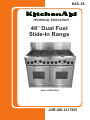
KitchenAid KDRP487MSS - 48" Pro-Style Dual Fuel Range W Technical Education
- Type
- Technical Education

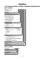
TECHNICAL EDUCATION
JOB AID 4317355
KAC-38
48″ Dual Fuel
Slide-In Range
Model: KDRP487MSS

- ii -
WHIRLPOOL CORPORATION assumes no responsibility for any repairs made
on our products by anyone other than Authorized Service Technicians.
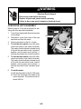
FORWARD
This KitchenAid Job Aid, “48″ Dual Fuel Slide-In Range,” (Part No. 4317355), provides the
technician with information on the installation, operation, and service of the 48″ Dual Fuel Slide-
In Range. It is to be used as a training Job Aid and Service Manual. For specific information on the
model being serviced, refer to the “Use and Care Guide,” or “Wiring Diagram” provided with the
range.
The Wiring Diagram and Strip Circuits used in this Job Aid are typical and should be used for
training purposes only. Always use the Wiring Diagram supplied with the product when servicing
the unit.
GOALS AND OBJECTIVES
The goal of this Job Aid is to provide detailed information that will enable the service technician to
properly diagnose malfunctions and repair the KitchenAid 48″ Dual Fuel Slide-In Range.
The objectives of this Job Aid are to:
• Understand and follow proper safety precautions.
• Successfully troubleshoot and diagnose malfunctions.
• Successfully perform necessary repairs.
• Successfully return the range to its proper operational status.
Copyright © 2004, Whirlpool Corporation, Benton Harbor, MI 49022

- iii -
TABLE OF CONTENTS
Page
GENERAL............................................................................................................................... 1-1
KitchenAid Model & Serial Number Designations.............................................................. 1-1
Model & Serial Number Label And Tech Sheet Locations................................................. 1-2
Specifications..................................................................................................................... 1-3
KitchenAid Warranty .......................................................................................................... 1-5
INSTALLATION INFORMATION ........................................................................................... 2-1
L.P. Gas Conversion.......................................................................................................... 2-1
Adjusting For The Proper Flame........................................................................................ 2-4
Installing The Anti-Tip Bracket ........................................................................................... 2-5
THEORY OF OPERATION ..................................................................................................... 3-1
Electronic Operation .......................................................................................................... 3-1
COMPONENT ACCESS ......................................................................................................... 4-1
Component Locations ........................................................................................................ 4-1
Removing The Cooktop, Burner Base, & Ignitor................................................................ 4-2
Removing The Control Panel And Components ................................................................ 4-4
Removing An Oven Door Latch Assembly & A Control Panel Thermal Fuse.................. 4-10
Removing The Main Electronic Control ........................................................................... 4-12
Removing A Halogen Lamp Assembly ............................................................................ 4-14
Removing A Broil Element ............................................................................................... 4-15
Removing An Oven Temperature Sensor........................................................................ 4-16
Removing A Rear Panel .................................................................................................. 4-17
Removing A Convection Bake Element & Fan Motor Assembly ..................................... 4-18
Removing A Blower Motor Assembly .............................................................................. 4-20
Removing The Suppressor Board ................................................................................... 4-21
Removing An Oven Shutdown Thermal Fuse ................................................................. 4-22
Removing A Hidden Bake Element ................................................................................. 4-23
Removing The Gas Distribution Valve ............................................................................. 4-25
Removing An Oven Door ................................................................................................. 4-26
Removing The Oven Door Glass, Hinges, & Handle ....................................................... 4-27
Removing The Oven Door Gasket................................................................................... 4-29

- iv -
Page
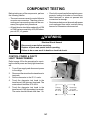
COMPONENT TESTING ........................................................................................................ 5-1
Control Power & Cavity Light Transformers ...................................................................... 5-1
Blower Motor...................................................................................................................... 5-2
Convection Bake Element ................................................................................................. 5-2
Oven Door Latch Assembly ............................................................................................... 5-3
Oven Temperature Sensor ................................................................................................ 5-4
Oven Shutdown Thermal Fuse .......................................................................................... 5-5
Convection Fan Motor ....................................................................................................... 5-5
Broil Element ..................................................................................................................... 5-6
Hidden Bake Element ........................................................................................................ 5-6
Ignition Switches ................................................................................................................ 5-7
DIAGNOSIS & TROUBLESHOOTING ................................................................................... 6-1
Diagnosis ........................................................................................................................... 6-1
Failure/Error Display Codes........................................................................................... 6-1
Control Panel Tests ...................................................................................................... 6-2
Oven Shutdown Thermal Fuse ...................................................................................... 6-2
Relay Logic .................................................................................................................... 6-3
WIRING DIAGRAM & STRIP CIRCUITS ............................................................................... 7-1
Wiring Diagram .................................................................................................................. 7-1
Strip Circuits ...................................................................................................................... 7-2

1-1
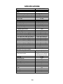
KITCHENAID MODEL & SERIAL NUMBER DESIGNATIONS
MODEL NUMBER
SERIAL NUMBER
GENERAL
MODEL NUMBER K DR P 48 7 M SS 0
INTERNATIONAL SALES IND.
OR MARKETING CHANNEL
IF PRESENT
PRODUCT GROUP
K = KITCHENAID
PRODUCT IDENTIFICATION
DD = DUAL FUEL DROP-IN / SLIDE-IN
DR = DUAL FUEL RANGE
ED = ELECTRIC DROP-IN RANGE
EE = ELECTRIC EYE-LEVEL RANGE
ER = ELECTRIC STANDARD RANGE
ES = ELECTRIC SLIDE-IN RANGE
GD = GAS DROP-IN RANGE
GE = GAS EYE-LEVEL RANGE
GR = GAS STANDARD RANGE
GS = GAS SLIDE-IN RANGE
MERCHANDISING SCHEME
C = CERAMIC GLASS TOP
H = CERAMIC W/HALOGEN
I = IMPERIAL
P = PROFESSIONAL / COMMERCIAL
S = STANDARD
T = TEMPERED GLASS TOP
CAPACITY / SIZE / SERIES / CONFIGURATION
1ST POSITION 2ND POSITION
1 = DROP-IN 0 = 30″ WIDE
2 = DROP-IN / SLIDE-IN COMBO 6 = 36″ WIDE
3 = SLIDE-IN 8 = 48″ WIDE
4 = COMMERCIAL
5 = STANDARD
7 = EYE-LEVEL
8 = 48″
9 = 60″
FEATURES
0 = STANDARD FEATURES
2 = PLUS FEATURES OR SEALED BURNERS
W / GRILL / CONVECTION OVEN
3 = SEALED BURNERS W / GRIDDLE / CONVECTION OVEN
4 = SEALED BURNERS W / GRILL & GRIDDLE / CONVECTION OVEN
5 = DELUXE FEATURES
7 = DELUXE FEATURES / CONVECTION OR
SEALED BURNERS / CONVECTION OVEN
YEAR OF INTRODUCTION
K= 2001, L - 2002, M = 2003
COLOR CODE
SS = STAINLESS STEEL
ENGINEERING CHANGE (NUMERIC)
SERIAL NUMBER X P 04 54321
MANUFACTURING SITE
X = OXFORD, MS
YEAR OF PRODUCTION
P = 2003, R = 2004
WEEK OF PRODUCTION
04 = 4th WEEK
PRODUCT SEQUENCE NUMBER

1-2
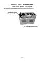
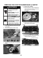
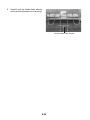
MODEL & SERIAL NUMBER LABEL
AND TECH SHEET LOCATIONS
The Model/Serial Number label and Tech Sheet locations are shown below.
Tech Sheet Location
(Behind Control Panel)
Model & Serial Number Location
(On Oven Frame Behind Door)

1-3
SPECIFICATIONS
Model Number KDRP487MSS
Dimensions/Specifications
Weight
Ratings Pigtail Required
Electric Voltage/Phase/Frequency(Hz) 240/208V, Single, 60 Hz
Total Connected Load In Kw 240 V Recommended
Circuit Amps 50 Amp
Exterior
Cabinet Finish Stainless
Control Panel Color Brushed Chrome
Control Knob Material Heavy Duty, Plastic
Cooktop Controls Infinite
Cooktop Control Type Push-to-Turn
Cooktop Control Location Front
Gas Cooktop Burners Yes
Gas Burner Type Sealed
Gas Right Front Output (BTU)(Nat/LP) 6000 BTU/2300 BTU
Gas Left Front Output (BTU)(Nat/LP) 6000 BTU/2300 BTU
Gas Right Rear Output (BTU)(Nat/LP) 15000 BTU/12000 BTU
Gas Left Rear Output (BTU)(Nat/LP) 15000 BTU/12000 BTU
Gas Center RF Output (BTU)(Nat/LP) 15000 BTU/12000 BTU
Gas Center RR Output (BTU)(Nat/LP) 15000 BTU/12000 BTU
Gas Center LF Output (BTU)(Nat/LP) 15000 BTU/12000 BTU
Gas Center LR Output (BTU)(Nat/LP) 15000 BTU/12000 BTU
Gas Ignition Cooktop Electronic
Gas Valves Degrees 210 degrees
Main/Single Oven Cycles or Options
Oven Control Type (Both Ovens) Electronic w/Knob Interface
Oven Control Location
Centered Over Oven,
Communicates & Coordinates
With Second Oven Control
Oven Broil 5 Levels
Closed Door Broil Yes
Convection 3rd Element
Oven Light Switch Automatic/Manual
Preheat Percentage Indication Yes
Sabbath Mode No
Selector Yes
Start Yes
Timer Yes
Cook Time Yes
Stop Time Yes

1-4
Model Number KDRP487MSS
Interior
Main Oven (Both Ovens)
Cooking System True Convection
Cleaning System Self Cleaning
Auto Self Clean Latch Yes
Main Oven Dimensions
Main Oven Volume (cu ft) 3.25; Usable: 2.86
Main Oven Height (in) 16"
Main Oven Width (in) 19"
Main Oven Depth (in) 18 1/2"; Usable: 16 1/4"
Rack Guides # 5
Oven Racks # 3
Oven Rack Type/# 3 Upper
Oven Light #/Location 2 Side Halogen
Main Hidden Bake Element Yes
Main Oven Bake (w@240/208v) 2000 W/1500 W
Main Oven Broil (w@240/208v) 2667 W/2000 W
Main Oven Convection (w@240/208v) 1600 W/1200 W
Accessories
Backsplash Part/Comment 9" Standard
Island Trim Part/Comment Standard
LP Conversion Kit Part/Comment Standard
Stainless Steel Cleaner Included
Wok Ring Optional (Part # 8284965)
Miscellaneous
Product Literature
Installation Instructions Part/Comment 8301285; Conversion, 8301283
Service Manual Part Number 4317355
Tech Sheet Part Number 8301281
Use & Care Guide Oven Part/Comment 8301284
Agency Approvals CSA, AGA, CGA
Anti-tip Device With Unit Yes
Residential Use Only Yes
Warranty
Full 12 Months, parts & labor
Extended
Electronic Controls 2nd Through 5th Year, Parts
Electrical Elements 2nd Through 5th Year, Parts
Porcelain Liner/Door 2nd Through 10th Year, Parts
Sealed Gas Burners 2nd Through 5th Year, Parts

1-5
KITCHENAID WARRANTY
ONE-YEAR FULL WARRANTY
For one year from the date of purchase, when this appliance is operated and maintained according to instructions
attached to or furnished with the product, KitchenAid will pay for factory specified parts and repair labor costs to
correct defects in materials or workmanship. Service must be provided by a KitchenAid-designated service com-
pany.
SECOND THROUGH FIFTH YEAR LIMITED WARRANTY ON ELECTRIC
ELEMENTS, CERAMIC GLASS COOKTOP, GAS BURNERS,
AND SOLID STATE TOUCH CONTROL SYSTEM
On electric ranges and electric cooktops, in the second through fifth years from the date of purchase, when this
appliance is operated and maintained according to instructions attached to or furnished with the product, KitchenAid
will pay for factory specified parts for any electric element to correct defects in materials or workmanship.
On ceramic glass ranges and ceramic gas cooktops, in the second through fifth years from the date of purchase,
when this appliance is operated and maintained according to instructions attached to or furnished with the product,
KitchenAid will pay for factory specified parts for the ceramic glass cooktop. KitchenAid warrants that the ceramic
glass cooktop will not discolor, the cooktop pattern will not wear off, the rubber seal between the ceramic glass
cooktop and porcelain edge will not crack, the ceramic glass cooktop will not crack due to thermal shock and the
surface unit elements will not burn out.
On gas ranges and gas cooktops, in the second through fifth years from the date of purchase, when this appliance
is operated and maintained according to instructions attached to or furnished with the product, KitchenAid will pay
for factory specified parts for any gas burner to correct defects in materials or workmanship.
On ranges and built-in ovens, in the second through fifth years from the date of purchase, when this appliance is
operated and maintained according to instructions attached to or furnished with the product, KitchenAid will pay for
factory specified parts for the porcelain oven cavity/inner door if the part rusts through due to defects in materials or
workmanship. KitchenAid will pay for factory specified parts for solid state touch control system and Magnetron
tube in combination ovens to correct defects in materials or workmanship.
SIXTH THROUGH TENTH YEAR LIMITED WARRANTY ON RANGES
AND BUILT-IN OVENS PORCELAIN OVEN CAVITY/INNER DOOR
On ranges and built-in ovens only, in the sixth through tenth years from the date of purchase, when this appliance
is operated and maintained according to instructions attached to or furnished with the product, KitchenAid will pay
for factory specified parts for the oven cavity/inner door if the part rusts through due to defects in materials or
workmanship.
KitchenAid will not pay for:
1. Service calls to correct the installation of your appliance, to instruct you how to use your appliance, to replace
house fuses or correct house wiring, or to replace owner-accessible light bulbs.
2. Repairs when your appliance is used in other than normal, single-family household use.
3. Pickup and delivery. Your appliance is designed to be repaired in the home.
4. Damage resulting from accident, alteration, misuse, abuse, fire, flood, improper installation, acts of God or use
of products not approved by KitchenAid or KitchenAid Canada.
5. Repairs to parts or systems resulting from unauthorized modifications made to the appliance.
6. Replacement parts or repair labor costs for units operated outside the United States or Canada.
7. In Canada, travel or transportation expenses for customers who reside in remote areas.
8. Any labor costs during the limited warranty periods.
KITCHENAID AND KITCHENAID CANADA SHALL NOT BE LIABLE
FOR INCIDENTAL OR CONSEQUENTIAL DAMAGES.
Some states or provinces do not allow the exclusion or limitation of incidental or consequential damages, so this
exclusion or limitation may not apply to you. This warranty gives you specific legal rights, and you may also have
other rights which vary from state to state or province to province.
Outside the 50 United States and Canada, this warranty does not apply. Contact your authorized KitchenAid
dealer to determine if another warranty applies.
If you need service, first see the “Troubleshooting” section of the Use and Care Guide. After checking “Trouble-
shooting,” additional help can be found by checking the “Assistance or Service” section, or by calling the KitchenAid
Customer Interaction Center, 1-800-422-1230 (toll-free), from anywhere in the U.S.A. In Canada, contact your
KitchenAid-designated service company, or call 1-800-807-6777.

1-6
— NOTES —

2-1
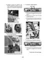
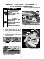
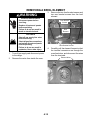
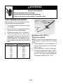
L.P. GAS CONVERSION
1. Check to make sure that the main gas
supply line to the range has been shut off,
(see below), and that the power supply
cord is disconnected from the AC outlet.
Gas Valve Handle
To “Shutoff” Position
Gas Supply To Range
Gas Supply Line
INSTALLATION INFORMATION
WARNING
Electrical Shock Hazard
Disconnect power before
servicing.
Replace all parts and panels
before operating.
Failure to do so can result in
death or electrical shock.
Fire Hazard
Shut off gas supply line valve.
Make all conversions before
turning gas supply valve back on.
Failure to follow these instructions
can result in explosion, fire, or
other injury.
NOTE: Gas conversion from natural to L.P.
gas must be done by a qualified installer.
2. To convert the cooktop burners for use
with L.P. gas:
a)Remove the grates and burner caps.
b)Remove the two T-20 torx screws from
each of the burner heads and remove
the heads from the cooktop.
NOTE: The L.P. orifices are fastened to the
back of the range near the bottom on a card-
board form.
Continued on the next page.
Burner Head
Orifice
Card

2-2
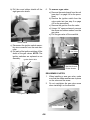
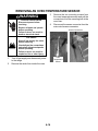
Gas Distribution Valve
d)Install the eight L.P. gas orifices in the
burners, as shown in the following
charts (do not overtighten them):
e)Place the natural gas orifices in the ori-
fice card holes.
3. To convert the gas distribution valve
for use with L.P. gas:
NOTE: The gas distribution valve on your
unit may look different than the one shown
in the procedure. However, the gas con-
version is the same.
a) Remove the bottom trim from the range.
b)Remove the three screws from each
end of the bottom trim and remove the
trim.
c) Use an 8 mm socket and carefully re-
move the orifice spud from each of the
four burners.
Surface
Burner
Orifice
8mm
Socket
3 Bottom Trim Screws
small
(red)
small
(red)
48" (121.92 cm) models
large
(blue)
large
(blue)
large
(blue)
large
(blue)
large
(blue)
large
(blue)
size stamp
or color
Rating Color Size Where Used
2,300 BTU red 0.70 mm small burners
12,000 BTU blue 1.10 mm large burners
burner orifice
small (red)
large (blue)

2-3
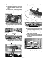
c) Unscrew the conversion cap from the
gas distribution valve and remove it and
the plastic cap. Note the difference be-
tween the L.P. and Natural gas ends of
the cap. NOTE: The valve you are ser-
vicing may not have a plastic cap.
Conversion Cap Set For Use
With (N) Natural Gas
Plastic Cap
L.P. Gas
d)Install the loop on the plastic cap over
the natural gas side of the conversion
cap.
e)Install the plastic cap and the conver-
sion cap on the gas distribution valve
with the L.P. side facing up (you will see
“LP” stamped inside the cap, as shown
below).
4. Reinstall the bottom trim.
5. Turn the gas supply valve handle on.
Gas Valve Handle
To “On” Position
Natural Gas
Conversion Cap
Set For L.P. Gas

2-4
COOKTOP BURNERS
1. Turn on one of the surface burners and set
the flame to its lowest (LOW) setting. The
flame should be steady and the inner cone
should be dark blue in color. The size
should be approximately 1/4″ (0.64 cm)
high.
2. If the low flame needs to be adjusted:
a)Remove the control knob.
b) Look inside the gas valve stem and note
the small screw. Insert a small screw-
driver into the gas valve stem and fit it
in the screw slot.
ADJUSTING FOR THE PROPER FLAME
c) Hold the gas valve stem with a pair of
pliers, and turn the screw in either di-
rection until the flame size is approxi-
mately 1/4″ high.
d)Replace the control knob.
e)Turn the control knob from HI to LO and
check to make sure that it remains ad-
justed properly.
f) Check the other burners, and adjust
them, if necessary.
Flame Adjustment Screw
Burner Valves

2-5
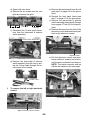
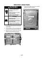
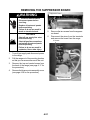
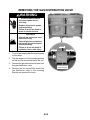
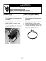
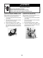
INSTALLING THE ANTI-TIP BRACKET
PARTS SUPPLIED
Plastic Anchors Screws
Anti-Tip Bracket
NOTE: The anti-tip bracket can be installed to
hold either the right or left rear leg of the range.
1. Determine which leg you wish to anchor to
the floor.
2. Place the anti-tip bracket template on the
floor in the range opening so that the top
edge is against the wall, molding, or cabi-
net, and the bracket template is in the
location where the anti-tip bracket will be
installed.
3. Tape the template to the floor.
Template
NOTE: For mounting to a wood floor, proceed
to step 4. For concrete or ceramic floors, pro-
ceed to step 5.
Template
Tip-Over Hazard
A child or adult can tip the range and
be killed.
Connect anti-tip bracket to rear range
foot.
Reconnect the anti-tip bracket, if the
range is moved.
Failure to follow these instructions can
result in death or serious burns to
children and adults.
WARNING

2-6
c) Remove the template from the floor.
d)Line up the two mounting holes in the
anti-tip bracket with the two holes you
just drilled in the floor.
e)Use the two screws that were supplied
and fasten the anti-tip bracket to the
floor.
4. To mount the anti-tip bracket to a wood
floor:
a)Use the bracket template to mark the
hole locations to be drilled.
b) Use a 1/8″ drill bit and drill the two holes.
5. To mount the anti-tip bracket to a con-
crete or ceramic floor:
a)Use the bracket template to mark the
hole locations to be drilled.
b)Use a 3/16″ drill bit and drill the two
holes.
c) Remove the template from the floor.
d)Tap the two plastic anchors into the
mounting holes with a hammer.
e)Line up the two mounting holes in the
anti-tip bracket with the two holes you
just drilled in the floor.
f) Use the two screws that were supplied
and fasten the anti-tip bracket to the
floor.
6. Move the range close to the cabinet open-
ing and plug the power supply cord into a
grounded outlet.
7. Remove the cardboard shipping piece from
under the range.
8. Move the range into position and make
sure that the rear leveling leg slides into
the anti-tip bracket, as shown.

3-1
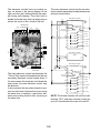
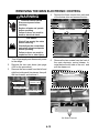
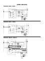
THEORY OF OPERATION
ELECTRONIC OPERATION
The components that control the electronic op-
eration of this range include the following:
Thermostat & Selector Switch Assembly
Electronic Control
(Secondary Board)
Main Electronic
Control
The two thermostat & selector switch assem-
blies are mounted on the front manifold panel,
and function the same as a touch pad on a
microwave oven.
Each oven has its own components, with the
exception of the main electronic control. The
main electronic control is used to synchronize
the two secondary boards for the displayed
“Time of Day.” It also monitors the secondary
boards to prevent two self-clean functions from
occurring at the same time. In addition, it pre-
vents a self-clean and cooking function from
occurring at the same time.
The main control is supplied with 24 VAC from
the control board power transformer. It com-
municates between the secondary oven elec-
tronic controls with 5 volt pulses from the main
control’s P9-1 yellow wire, and uses the P9-3
orange wire as a ground reference. If the main
control malfunctions, an F04 error code will be
indicated in the clock displays. Refer to the
Tech Sheet that is supplied with the unit for
additional information.
As you turn a selector switch to a particular
setting, (i.e. Bake, Broil, Clean, etc.), individual
relays on the oven’s electronic control close,
and the appropriate circuits are completed.
RESET
BAKE
CONV. BAKE-PREHEAT
CONV. ROAST-PREHEAT
BREAD-PREHEAT
KEEP WARM
CONV. BAKE
BROIL
MODES
BAKE
BROIL
CONV ELEM
CONV FAN
LIGHT
BLOWER
BAKE PREHEAT
CONV. BROIL-PREHEAT
PROOF
CLEAN
RELAYS
BROILPREHEAT
CONV. BROIL
CONV. ROAST
BREAD BAKING
OFF
ON
CYCLING (MAX. PERIOD = 60 SEC.)
RELAY LOGIC KEY
NOTE: DURING THE SELF CLEAN FUNCTION,
THE OTHER OVEN CANNOT OPERATE.
ON OR OFF
Thermostat & Selector Switch Assemblies

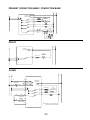
3-2
P5
P7
Not Used
Not Used
BL R Y
20
JP18 JP19
BK BK
21 22
P1
Double Line
Break Relay
BK OR GY
P8
OR
OR
Y
Y Y BK
P3
Thermostat & Selector Sw.
Connector
P9
BK
BK
P4
GN BU BU
The main electronic control synchronizes the
“Time of Day” readout information that the two
secondary electronic control boards share. If
for some reason the clocks do not indicate the
exact times, the main electronic control may
be defective.
It also monitors the secondary boards to pre-
vent two self-clean functions from occurring at
the same time. In addition, it prevents a self-
clean and cooking function from occurring at
the same time.
The electronic controls have six cooking re-
lays, as shown in the wiring diagram to the
right, and two door latching relays that oper-
ate during self-cleaning. They also have a
double line break relay that is a safety relay to
control the circuit to the L2 side of the line.
L2
L1
GRN
BK
BK
P4-1
P4-2
P7-4
P7-2
P7-3
P3-1
P1-3
P5-4
P5-1
P5-3
P1-1
P1-5
P7-1
R
R
P7-5
DOUBLE LINE
BREAK RELAY
P9-1
P9-3
Y
ORG
P3-2
P3-3
P3-2
P3-3
P9-1
P9-3
Y
ORG
LS2
LS1
BK
P8-1
P8-3
P8-2
P8-4
BK
BK
W1
GRN
BK
BK
P4-1
P4-2
P7-4
P7-2
P7-3
P3-1
P1-3
P5-4
P5-1
P5-3
P1-1
P1-5
P7-1
R
R
BU (BROIL)
OR (DOOR
LATCH MTR)
OR (DOOR
LATCH MTR)
R (BAKE)
Y (CONV)
GY (BLOWER)
OR (CONV
FAN)
BK (LIGHTS)
BU (BROIL)
R (BAKE)
Y (CONV)
GY (BLOWER)
OR (CONV
FAN)
BK (LIGHTS)
P7-5
DOUBLE LINE
BREAK RELAY
P9-1
P9-3
Y
ORG
RS2
RS1
P3-2
P3-3
BK
BK
P8-1
P8-3
P8-2
P8-4
BK
MAIN
BK
BK
BK
Y
ORG
ELECTRONIC CONTROL
ELECTRONIC CONTROL
ELECTRONIC CONTROL
LEFT SECONDARY
RIGHT SECONDARY
NOTE: The blower remains off until the oven
reaches 190°F, and may continue running for
up to 45 minutes after the oven is turned off.
The main electronic control and the two elec-
tronic controls (secondary boards) interconnect
wiring is shown below.

4-1
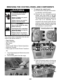
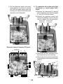
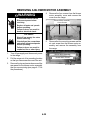
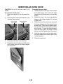
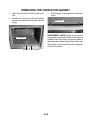
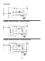
COMPONENT LOCATIONS
This section instructs you on how to service each component inside the 48″ Dual Fuel Slide-In
Range. The components and their locations are shown below.
COMPONENT ACCESS
Door Latch Assembly
Right Clock Assembly
Right Electronic Control
Door Gasket
Suppressor Board
Burner Base & Ignitor
Oven Light Switch
Right Control Panel
Thermal Fuse
Right Thermostat &
Selector Switch Assemby
Left Thermostat &
Selector Switch Assemby
Spark Modules
Main Electronic Control
Oven Temperature Sensor
(On Rear Panel)
Oven Light Switch
Door Latch Assembly
Hidden Bake Element
Hidden Bake Element
Door Gasket
Left Electronic
Control
Blower Motor
Broil Element
Control Power Transformer
Blower Motor
Broil Element
Tech Sheet
Oven Shutdown Thermal Fuse
(On Rear Panel)
Halogen Lamp
Control Power Transformer
Cavity Light Transformer
Convection Fan Motor
& Ring Element
Convection Fan Motor & Ring Element
Oven Shutdown Thermal Fuse (On Rear Panel)
Oven Temperature Sensor (On Rear Panel)
Cavity Light Transformer

4-2
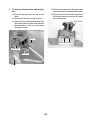
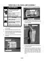
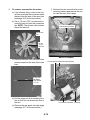
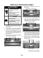
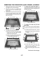
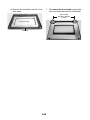
REMOVING THE COOKTOP, BURNER BASE, & IGNITOR
WARNING
1. Turn off gas supply and disconnect power
to the range.
2. Remove the grates from the range.
Electrical Shock Hazard
Disconnect power before
servicing.
Replace all parts and panels
before operating.
Failure to do so can result in
death or electrical shock.
Fire Hazard
Shut off gas supply line valve
before servicing.
Check all gas line connections
and replace all parts and panels
before operating.
Failure to do so can result in
explosion, fire or other injury.
4. To remove the cooktop:
a) Remove the two T-20 torx screws from
each of the burner heads and remove
the heads from the cooktop.
3. Remove the burner caps from the burner
heads.
b) Remove the screws from the front and
rear corners of the cooktop.
c) Lift the rear of the cooktop and pull the
cooktop off the top of the unit.
Screws
Screws
Lift Rear Of Cooktop
Burner Head
Page is loading ...
Page is loading ...
Page is loading ...
Page is loading ...
Page is loading ...
Page is loading ...
Page is loading ...
Page is loading ...
Page is loading ...
Page is loading ...
Page is loading ...
Page is loading ...
Page is loading ...
Page is loading ...
Page is loading ...
Page is loading ...
Page is loading ...
Page is loading ...
Page is loading ...
Page is loading ...
Page is loading ...
Page is loading ...
Page is loading ...
Page is loading ...
Page is loading ...
Page is loading ...
Page is loading ...
Page is loading ...
Page is loading ...
Page is loading ...
Page is loading ...
Page is loading ...
Page is loading ...
Page is loading ...
Page is loading ...
Page is loading ...
Page is loading ...
Page is loading ...
Page is loading ...
Page is loading ...
Page is loading ...
Page is loading ...
Page is loading ...
Page is loading ...
Page is loading ...
Page is loading ...
Page is loading ...
Page is loading ...
-
 1
1
-
 2
2
-
 3
3
-
 4
4
-
 5
5
-
 6
6
-
 7
7
-
 8
8
-
 9
9
-
 10
10
-
 11
11
-
 12
12
-
 13
13
-
 14
14
-
 15
15
-
 16
16
-
 17
17
-
 18
18
-
 19
19
-
 20
20
-
 21
21
-
 22
22
-
 23
23
-
 24
24
-
 25
25
-
 26
26
-
 27
27
-
 28
28
-
 29
29
-
 30
30
-
 31
31
-
 32
32
-
 33
33
-
 34
34
-
 35
35
-
 36
36
-
 37
37
-
 38
38
-
 39
39
-
 40
40
-
 41
41
-
 42
42
-
 43
43
-
 44
44
-
 45
45
-
 46
46
-
 47
47
-
 48
48
-
 49
49
-
 50
50
-
 51
51
-
 52
52
-
 53
53
-
 54
54
-
 55
55
-
 56
56
-
 57
57
-
 58
58
-
 59
59
-
 60
60
-
 61
61
-
 62
62
-
 63
63
-
 64
64
-
 65
65
-
 66
66
-
 67
67
-
 68
68


KitchenAid KDRP487MSS - 48" Pro-Style Dual Fuel Range W Technical Education
- Type
- Technical Education
Ask a question and I''ll find the answer in the document
Finding information in a document is now easier with AI
Related papers
-
KitchenAid KGRT507BAL3 Owner's manual
-
-
-
KitchenAid KGRT507GBT0 Owner's manual
-
KitchenAid KGRT607HBS0 Owner's manual
-
-
-
-
KitchenAid KDRP462LSS08 Owner's manual
-
Other documents
-
Kenroy Home 32174CH Installation guide
-
PREMIUM PBO6524DM User manual
-
ATD Tools ATD-500 User manual
-
Scotsman Replacement Transformer - 17-2520-01 Operating instructions
-
Whirlpool KR-28 User manual
-
Frigidaire FFEF3010UB Product information
-
-
Elmira Stove Works 1955 User manual
-
-
 KichenAid KitchenAid Double Oven Gas Range Owner's manual
