Page is loading ...

ISTRUZIONI D’USO E DI INSTALLAZIONE
INSTALLATION AND USER’S MANUAL
INSTRUCTIONS D’UTILISATION ET D’INSTALLATION
INSTALLATIONS-UND GEBRAUCHSANLEITUNG
INSTRUCCIONES DE USO Y DE INSTALACION
INSTALLATIEVOORSCHRIFTEN
AUTOMAZIONI A BRACCIO PER CANCELLI A BATTENTE
ARM-OPERATED AUTOMATION FOR SWING GATES
AUTOMATISATIONS À BRAS POUR PORTAILS À BATTANT
AUTOMATISIERUNG MIT GELENKARM FÜR DREHTORE
AUTOMATIZACIONES CON BRAZO PARA CANCELAS BATIENTES
ARMAUTOMATISERINGSSYSTEMEN VOOR VLEUGELPOORTEN
Attenzione! Leggere attentamente le “Avvertenze” all’interno! Caution! Read “Warnings” inside carefully! Attention! Veuillez lire attentivement les Avertissements qui se trouvent à l’intérieur! Achtung! Bitte lesen Sie
aufmerksam die „Hinweise“ im Inneren! ¡Atención¡ Leer atentamente las “Advertencias”en el interior! Let op! Lees de “Waarschuwingen” aan de binnenkant zorgvuldig!
D811898 00100_01 30-05-12
A-200 SW
8
027908 414045

B
C
D
390
230
120˚
90˚
Max. 210
335
300 MIN
30
123
63
300 MIN
135123
63
D1
D1
*1 Right / Droite / Rechts /
Derecha / Direita
* 2 Left / Gauche / Links /
Izquierda / Esquerda
8
m8
A
6X1.5 mm
2
2x0.75 mm
2
4x0.75 mm
2
6x1.5 mm
2
3x1.5 mm
2
INSTALLAZIONE VELOCE-QUICK INSTALLATION-INSTALLATION RAPIDE
SCHNELLINSTALLATION-INSTALACIÓN RÁPIDA - SNELLE INSTALLATIE
a) Prima di iniziare con l’installazione bisogna leggere le avvertenze.
a) Before commencing installation, make sure you read the warnings.
a) Avant de commencer l’installation lisez les avertissements.
a) Vor der Installation müssen die Hinweise gelesen werden.
a) Antes de comenzar con la instalación es necesario leer las adver-
tencias.
a) Voor met de installatie te beginnen moet u de waarschuwingen lezen.
b) Oltre alle gure, bisogna seguire le indicazioni date nel paragrafo corrispondente a pag.6
b) In addition to the gures, you must follow the instructions given in the relevant section on page 8
b) Suivez non seulement les gures mais aussi les indications données dans le paragraphe correspondant à
la page 10
b) Außer den Abbildungen müssen die Angaben im entsprechenden Abschnitt auf Seite 12 befolgt werden
b) Además de las guras, es necesario seguir las indicaciones dadas en el apartado correspondiente en pág. 14
b) Volg niet alleen de guren, maar ook de aanwijzingen die in de paragraaf op pag. 16 staan
PREDISPOSIZIONE TUBI, TUBE ARRANGEMENT,
PRÉDISPOSITION DES TUYAUX, VORBEREITUNG DER LEITUNGEN,
DISPOSICIÓN DE TUBOS, VOORBEREIDING LEIDINGEN.
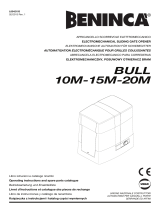
QUOTE E INSTALLAZIONI COMUNI / DISTANCES AND COMMON INSTALLATIONS / COTES ET INSTALLATIONS COMMUNES
ALLGEMEINE INSTALLATIONSMASSE / COTAS E INSTALACIONES COMUNES / AFSTANDEN EN NORMALE INSTALLATIES
FISSAGGIO PIASTRA DI SUPPORTO
FASTENING THE MOUNTING PLATE
FIXATION PLAQUE DE SUPPORT
BEFESTIGUNG DER VERANKERUNGSPLATTE
FIJACIÓN PLACA DE SOPORTE
BEVESTIGING VAN DE
STEUNPLAAT
ASSEMBLAGGIO BRACCIO A LEVE
LEVER ARM ASSEMBLY
ASSEMBLAGE BRAS À LEVIER
MONTAGE DES HEBELARMS
ENSAMBLADO BRAZO DE PALANCAS
MONTAGE VAN DE ARM
2 - A- 200 SW

ITALIANO ENGLISH
FRANÇAIS
DEUTSCH
ESPAÑOL
NEDERLANDS
E
G
F
F1
635
V2
V1
R1
D2
R2
R2
V2
R1
D2
V1
8
6,5
8
8
8,5
6
6
18
ASSEMBLAGGIO BRACCIO A LEVE
LEVER ARM ASSEMBLY
ASSEMBLAGE BRAS À LEVIER
MONTAGE DES HEBELARMS
ENSAMBLADO BRAZO DE PALANCAS
MONTAGE VAN DE ARM
FISSAGGIO ATTUATORE SU PIASTRA DI ANCORAGGIO
FASTENING THE ACTUATOR ON THE ANCHOR PLATE
FIXATION ACTIONNEUR SUR PLAQUE D’ANCRAGE
BEFESTIGUNG DES ANTRIEBES AUF DER VERANKERUNGSPLATTE
FIJACIÓN ACCIONADOR EN PLACA DE ANCLAJE
BEVESTIGING VAN DE ACTUATOR OP DE BEVESTIGINGSPLAAT
POSIZIONE ATTACCO ANTA / LEAF ATTACHMENT POSITION/ POSITION CORRECTE BRAS
POSITION DER ANBRINGUNG DES TORFLÜGELS / POSICIÓN FIJACIÓN HOJA / BEVESTIGINGSPOSITIE VLEUGEL
FISSAGGIO BLOCCHI DI ARRESTO
FASTENING THE STOPS
FIXATION BLOCS D’ARRÊT
BEFESTIGUNG DER ANSCHLÄGE
FIJACIÓN BLOQUEOS DE PARADA
BEVESTIGING EINDSTOPPEN
A-200 SW -
3
D811898 00100_01

H
I J
K
3
46 5 2 1
ENC V+
ENC V-
+
-
ENC A
ENC B
M
V3
253.5
216 180
V3
45
4,2
COLLEGAMENTI MORSETTIERA
TERMINAL STRIP WIRING
CONNEXIONS BORNIER
ANSCHLÜSSE DER KLEMMLEISTE
CONEXIÓNES TABLERO DE BORNES
AANSLUITINGEN AANSLUITKAST
FISSAGGIO COPERCHIO
FASTENING THE COVER
FIXATION COUVERCLE
BEFESTIGUNG DER ABDECKUNG
FIJACIÓN TAPA
BEVESTIGING DEKSEL
Passaggio cavi /Cable routing / Passage de câbles/
Abeldurchführung/Paso de los cables/ Kabeldoorgang
Pressacavo / Cable gland / Presse-étoupe /
Kabelklemme / Sujetacable / Kabelklem
Aletta da strappare
Fin to pull out
Partie pré-découpée
Zu entfernende Rippe
Aleta para arrancar
Af te breken lipje
4 -
A- 200 SW

ENGLISH
INSTALLER WARNINGS
Anything that is not explicitly provided for in the installation ma-
nual is not allowed. The operator’s proper operation can only be
guaranteed if the information given is complied with. The Firm shall
not be answerable for damage caused by failure to comply with the
instructions featured herein.
While we will not alter the product’s essential features, the Firm re-
serves the right, at any time, to make those changes deemed oppor-
tune to improve the product from a technical, design or commercial
point of view, and will not be required to update this publication
accordingly.
WARNING! Important safety instructions. Carefully read and comply with
all the warnings and instructions that come with the product as incorrect
installation can cause injury to people and animals and damage to property.
The warnings and instructions give important information regarding safety,
installation, use and maintenance. Keep hold of instructions so that you can
attach them to the technical le and keep them handy for future reference.
GENERAL SAFETY
This product has been designed and built solely for the purpose indicated herein.
Uses other than those indicated herein might cause damage to the product and
create a hazard.
- The units making up the machine and its installation must meet the requirements
of the following European Directives, where applicable: 2004/108/EC, 2006/95/
EC, 2006/42/EC, 89/106/EC, 99/05/EC and later amendments. For all countries
outside the EEC, it is advisable to comply with the standards mentioned, in ad-
dition to any national standards in force, to achieve a good level of safety.
- The Manufacturer of this product (hereinafter referred to as the “Firm”) disclaims
all responsibility resulting from improper use or any use other than that for
which the product has been designed, as indicated herein, as well as for failure
to apply Good Practice in the construction of entry systems (doors, gates, etc.)
and for deformation that could occur during use.
- Before installing the product, make all structural changes required to produce
safety gaps and to provide protection from or isolate all crushing, shearing and
dragging hazard areas and danger zones in general in accordance with the
provisions of standards EN 12604 and 12453 or any local installation standards.
Check that the existing structure meets the necessary strength and stability
requirements.
- Before commencing installation, check the product for damage.
- The Firm is not responsible for failure to apply Good Practice in the construction
and maintenance of the doors, gates, etc. to be motorized, or for deformation
that might occur during use.
- Make sure the stated temperature range is compatible with the site in which the
automated system is due to be installed.
- Do not install this product in an explosive atmosphere: the presence of ammable
fumes or gas constitutes a serious safety hazard.
- Disconnect the electricity supply before performing any work on the system.
Also disconnect buer batteries, if any are connected.
- Before connecting the power supply, make sure the product’s ratings match the
mains ratings and that a suitable residual current circuit breaker and overcurrent
protection device have been installed upline from the electrical system. Have
the automated system’s mains power supply tted with a switch or omnipolar
thermal-magnetic circuit breaker with a contact separation that meets code
requirements.
- Make sure that upline from the mains power supply there is a residual current
circuit breaker that trips at no more than 0.03A as well as any other equipment
required by code.
- Make sure the earth system has been installed correctly: earth all the metal parts
belonging to the entry system (doors, gates, etc.) and all parts of the system
featuring an earth terminal.
- Installation must be carried out using safety devices and controls that meet
standards EN 12978 and EN 12453.
- Impact forces can be reduced by using deformable edges.
- In the event impact forces exceed the values laid down by the relevant standards,
apply electro-sensitive or pressure-sensitive devices.
- Apply all safety devices (photocells, safety edges, etc.) required to keep the
area free of impact, crushing, dragging and shearing hazards. Bear in mind the
standards and directives in force, Good Practice criteria, intended use, the instal-
lation environment, the operating logic of the system and forces generated by
the automated system.
- Apply all signs required by current code to identify hazardous areas (residual
risks). All installations must be visibly identied in compliance with the provisions
of standard EN 13241-1.
- Once installation is complete, apply a nameplate featuring the door/gate’s data.
- This product cannot be installed on leaves incorporating doors (unless the motor
can be activated only when the door is closed).
- If the automated system is installed at a height of less than 2.5 m or is accessible,
the electrical and mechanical parts must be suitably protected.
- Install any xed controls in a position where they will not cause a hazard, away
from moving parts. More specically, hold-to-run controls must be positioned
within direct sight of the part being controlled and, unless they are key operated,
must be installed at a height of at least 1.5 m and in a place where they cannot
be reached by the public.
- Apply at least one warning light (ashing light) in a visible position, and also
attach a Warning sign to the structure.
- Attach a label near the operating device, in a permanent fashion, with informa-
tion on how to operate the automated system’s manual release.
- Make sure that, during operation, mechanical risks are avoided or relevant
protective measures taken and, more specically, that nothing can be banged,
crushed, caught or cut between the part being operated and surrounding parts.
- Once installation is complete, make sure the motor automation settings are
correct and that the safety and release systems are working properly.
- Only use original spare parts for any maintenance or repair work. The Firm dis-
claims all responsibility for the correct operation and safety of the automated
system if parts from other manufacturers are used.
- Do not make any modications to the automated system’s components unless
explicitly authorized by the Firm.
- Instruct the system’s user on what residual risks may be encountered, on the
control systems that have been applied and on how to open the system manu-
ally in an emergency. give the user guide to the end user.
- Dispose of packaging materials (plastic, cardboard, polystyrene, etc.) in accord-
ance with the provisions of the laws in force. Keep nylon bags and polystyrene
out of reach of children.
WIRING
WARNING! For connection to the mains power supply, use: a multicore cable with
a cross-sectional area of at least 5x1.5mm
2
or 4x1.5mm
2
when dealing with three-
phase power supplies or 3x1.5mm
2
for single-phase supplies (by way of example,
type H05 VV-F cable can be used with a cross-sectional area of 4x1.5mm
2
). To con-
nect auxiliary equipment, use wires with a cross-sectional area of at least 0.5 mm
2
.
- Only use pushbuttons with a capacity of 10A-250V or more.
- Wires must be secured with additional fastening near the terminals (for example,
using cable clamps) in order to keep live parts well separated from safety extra
low voltage parts.
- During installation, the power cable must be stripped to allow the earth wire
to be connected to the relevant terminal, while leaving the live wires as short
as possible. The earth wire must be the last to be pulled taut in the event the
cable’s fastening device comes loose.
WARNING! safety extra low voltage wires must be kept physically separate from
low voltage wires.
Only qualied personnel (professional installer) should be allowed to access
live parts.
CHECKING THE AUTOMATED SYSTEM AND MAINTENANCE
Before the automated system is nally put into operation, and during maintenance
work, perform the following checks meticulously:
- Make sure all components are fastened securely.
- Check starting and stopping operations in the case of manual control.
- Check the logic for normal or personalized operation.
- For sliding gates only: check that the rack and pinion mesh correctly with 2 mm
of play along the full length of the rack; keep the track the gate slides on clean
and free of debris at all times.
- For sliding gates and doors only: make sure the gate’s running track is straight
and horizontal and that the wheels are strong enough to take the weight of the
gate.
- For cantilever sliding gates only: make sure there is no dipping or swinging
during operation.
- For swing gates only: make sure the leaves’ axis of rotation is perfectly vertical.
- Check that all safety devices (photocells, safety edges, etc.) are working properly
and that the anti-crush safety device is set correctly, making sure that the force
of impact measured at the points provided for by standard EN 12445 is lower
than the value laid down by standard EN 12453.
- Impact forces can be reduced by using deformable edges.
- Make sure that the emergency operation works, where this feature is provided.
- Check opening and closing operations with the control devices applied.
- Check that electrical connections and cabling are intact, making extra sure that
insulating sheaths and cable glands are undamaged.
- While performing maintenance, clean the photocells’ optics.
- When the automated system is out of service for any length of time, activate the
emergency release (see “EMERGENCY OPERATION” section) so that the operated
part is made idle, thus allowing the gate to be opened and closed manually.
-
If the power cord is damaged, it must be replaced by the manufacturer or their
technical assistance department or other such qualied person to avoid any risk .
- If “D” type devices are installed (as dened by EN12453), connect in unveried
mode, foresee mandatory maintenance at least every six months
WARNING!
Remember that the drive is designed to make the gate/door easier to use and
will not solve problems as a result of defective or poorly performed installation
or lack of maintenance
SCRAPPING
Materials must be disposed of in accordance with the regulations in force. There
are no particular hazards or risks involved in scrapping the automated system. For
the purpose of recycling, it is best to separate dismantled parts into like materials
(electrical parts - copper - aluminium - plastic - etc.).
DISMANTLING
If the automated system is being dismantled in order to be reassembled at another
site, you are required to:
- Cut o the power and disconnect the whole electrical system.
- Remove the actuator from the base it is mounted on.
- Remove all the installation’s components.
- See to the replacement of any components that cannot be removed or happen
to be damaged.
AVVERTENZE PER L’INSTALLATORE D811766_06
A-200 SW - 7
D811898 00100_01

INSTALLATION MANUAL
1) GENERAL INFORMATION
Low-voltage (24V) actuator suitable for residential use. Designed for
swing gates with small pillars. The operating arm, made in a special
non-scissoring design, allows the leaves to be moved even with the
actuator set some distance from the leaves’ fulcrum. The irreversible
electromechanical gearbox keeps the gate locked closed and open.
The release lever, located on the outside of each actuator, makes moving
the gate manually extremely easy.
2) TECHNICAL SPECIFICATIONS
MOTOR
Power supply 24V
Power input 40W
Opening time 90° 14 s
Max. leaf weight and
length
2000N (~200kg) for leaf 2m long
Max. torque 170Nm
Nominal Torque 50Nm
Impact reaction
Torque limiter built into A-CT BOARD SW 200
control panel
Lubrication Lifetime greased
Manual operation Release lever with CLS key
Type of use
Intensive
Environmental
conditions
from -20°C to + 50°C
Protection rating IP44
Operator weight 6 kg
Dimensions See Fig. J
3) TUBE ARRANGEMENT Fig.A
Install the electrical system referring to the standards in force for elec-
trical systems CEI 64-8, IEC 364, harmonization document HD 384 and
other national standards.
4) INSTALLING THE AUTOMATION SYSTEM
4.1 PRELIMINARY CHECKS
Check that:
• Thegate’sstructureissucientlysturdyandrigid.
Determine the most suitable fastening position based on the leaf’s
structure. Whatever the case, the operating arm must push against a
reinforced point of the leaf (Fig. B).
• Theleavescanbepushedallthewayopenandclosedbyhand.
If the gate is not a newly installed one, check the state of repair of all
its components. Fix or replace defective or worn parts.
The automation system’s reliability and safety are aected directly by
the state of the gate’s structure.
4.2) DISTANCES AND COMMON INSTALLATIONS (FIG. B)
4.3) FASTENING THE MOUNTING PLATE (FIG. C)
In the event the pillar surface is uneven, use through bolt expansion
anchors/screws with plastic anchors so you can adjust the fastening
bracket parallel to the leaf.
4.4) LEVER ARM ASSEMBLY (FIG. D)
4.5) FASTENING THE ACTUATOR ON THE ANCHOR PLATE (FIG. E)
4.6) LEAF ATTACHMENT POSITION (FIG. F1)•
The correct position the actuator arm should be installed in is pictured
in Fig. F. The point (Fig. F1) at which it is attached to the leaf is determi-
ned by positioning the arm so that the distance matches the distance
illustrated in Fig. F.
•Withtheactuatorreleased,checkthatthearmmovesproperly.
•Repeatthisprocedurefortheotherleaf.
4.7) FASTENING THE STOPS (FIG. G).
The A-200 actuator comes with mechanical travel limit stops. Nonetheless,
you can still install stops on the ground.
Referring to Fig. G, locate the opening and closing travel limits and fasten
the stops accordingly.
5) TERMINAL STRIP WIRING (FIG. H)
6) FASTENING THE COVER (FIG. I)
7) ACTUATOR DIMENSIONS (FIG. J)
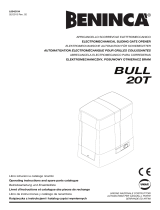
8) WIRE-PULL MANUAL RELEASE DEVICE (Fig. K)
The actuator’s emergency release can be operated by a wire-pull device:
- Remove the whole metal cable from the sheath and insert it in the
release lever.
- Secure the sheath and adjust its position as required with the relevant
screw.
- The cover features a tab that you need to pull in order to feed the
sheath through.
- For further information, refer to the specic instructions for the release
device.
8 - A- 200 SW

A
FIG. 2
D
B
C
E
F
ON
OFF
ON
click
MANUALE D’USO: MANOVRA MANUALE/ USER’S MANUAL: MANOVRA MANUALE/ MANUEL D’UTILISATION: MANOVRA MANUALE/
BEDIENUNGSANLEITUNG: MANOVRA MANUALE/ MANUEL DE USO: MANOVRA MANUALE/ MANUAL PARA DE USO: MANOVRA MANUALE
A-200 SW - 17
D811898 00100_01

USER WARNINGS (GB)
WARNING! Important safety instructions. Carefully read and comply with the Warnings
and Instructions that come with the product as improper use can cause injury to people
and animals and damage to property. Keep the instructions for future reference and hand
them on to any new users.
This product is meant to be used only for the purpose for which it was explicitly installed.
Any other use constitutes improper use and, consequently, is hazardous. The manufacturer
cannot be held liable for any damage as a result of improper, incorrect or unreasonable use.
GENERAL SAFETY
Thank you for choosing this product. The Firm is condent that its performance will meet your
operating needs.
This product meets recognized technical standards and complies with safety provisions when installed
correctly by qualied, expert personnel (professional installer).
If installed and used correctly, the automated system will meet operating safety standards.
Nonetheless, it is advisable to observe certain rules of behaviour so that accidental problems
can be avoided:
- Keep adults, children and property out of range of the automated system, especially while it is
moving.
- Do not allow children to play or stand within range of the automated system.
- This automated system is not meant for use by children or by people with impaired mental,
physical or sensory capacities, or people who do not have suitable knowledge, unless a person
who is responsible for their safety provides them with necessary supervision or instructions on
how to use the device.
- Children must be supervised to ensure they do not play with the device. Do not allow children
to play with the xed controls. Keep remote controls out of reach of children.
- Do not work near hinges or moving mechanical parts.
- Do not hinder the leaf’s movement and do not attempt to open the door manually unless the
actuator has been released with the relevant release knob.
- Keep out of range of the motorized door or gate while they are moving.
- Keep remote controls or other control devices out of reach of children in order to avoid the
automated system being operated inadvertently.
- The manual release’s activation could result in uncontrolled door movements if there are me-
chanical faults or loss of balance.
- When using roller shutter openers: keep an eye on the roller shutter while it is moving and keep
people away until it has closed completely. Exercise care when activating the release, if such a
device is tted, as an open shutter could drop quickly in the event of wear or breakage.
- The breakage or wear of any mechanical parts of the door (operated part), such as cables, springs,
supports, hinges, guides…, may generate a hazard. Have the system checked by qualied, expert
personnel (professional installer) at regular intervals according to the instructions issued by the
installer or manufacturer of the door.
- When cleaning the outside, always cut o mains power.
- Keep the photocells’ optics and illuminating indicator devices clean. Check that no branches or
shrubs interfere with the safety devices.
- Do not use the automated system if it is in need of repair. In the event the automated system
breaks down or malfunctions, cut o mains power to the system; do not attempt to repair or
perform any other work to rectify the fault yourself and instead call in qualied, expert personnel
(professional installer) to perform the necessary repairs or maintenance. To allow access, activate
the emergency release (where tted).
- If any part of the automated system requires direct work of any kind that is not contemplated
herein, employ the services of qualied, expert personnel (professional installer).
- At least once a year, have the automated system, and especially all safety devices, checked
by qualied, expert personnel (professional installer) to make sure that it is undamaged and
working properly.
- A record must be made of any installation, maintenance and repair work and the relevant
documentation kept and made available to the user on request.
- Failure to comply with the above may result in hazardous situations.
Anything that is not explicitly provided for in the user guide is not allowed. The operator’s
proper operation can only be guaranteed if the instructions given herein are complied
with. The Firm shall not be answerable for damage caused by failure to comply with the
instructions featured herein.
While we will not alter the product’s essential features, the Firm reserves the right, at any
time, to make those changes deemed opportune to improve the product from a technical,
design or commercial point of view, and will not be required to update this publication
accordingly.
A- 200 SW

/