Westinghouse R6GI Installation guide

Type
Installation guide

This manual is also suitable for

Installation Instructions
Skirt Trim Kit – 919729(B)
INTRODUCTION
This Skirt Trim Kit contains four color coordinated
sheet metal panels which mount over the unpainted
unit base rails. When assembled per these instruc-
tions they will provide a clean fi nished appearance.
They are primarily designed for units that are in-
stalled at ground level where they are visible to the
general public; however they may also be installed
on roof mounted units to enhance the overall ap-
pearance of the equipment.
Rail Covers Installed
Rail Covers
This Kit Includes:
a. Installation Instructions – Part Number 708738
b. Two (2) Long Rail Covers – Part Number 29611(B)
c. Two (2) Short Rail covers – Part Number 28612(B)
d. Ten (10) #10 Sheet Metal Screws x 1 1/4" long.
Long Rail Cover
Long Rail Cover
Short Rail Cover
Short Rail Cover
2
INSTALLATION
1. Remove only the three (3) sheet metal screws from
the long base rails and only the two (2) sheet metal
screws from the short base rails on each side which
corresponds to the slotted holes in the rail covers.
(See Figure 1a and Figure 1b below) Note the base
rails will remain attached to the base pan with the
screws you have not removed. DO NOT DISCARD
THE SCREWS REMOVED. You will reuse eight (8)
of these screws later in the corner fl anges of the rail
covers, see Step 6 below.
Figure 1b
NOTE: If the underside shipping boards and brackets
have not been removed from the unit they should be
removed before proceeding. Do not discard the shipping
boards and brackets if there is a chance that the Unit will
have to be handled with a fork truck in the future.
Figure 1a
Remove Screw
Remove Screw
Remove ScrewRemove Screw
Remove Screw
Remove Screw
Remove Screw
Remove Screw
Remove Screw
Remove Screw
3
2. Install the fi rst long rail cover by hooking the offset
anges of the rail cover into the fork truck openings
of the base rail. (See Figure 2a below) Then rotate
the rail cover up against the base pan wherein the
upper edge of the rail cover is above the base rail
and below the side sheet metal. (See Figure 2b
below) Then where you had removed the #10 x ½”
screws in step 1 use the #10 x 1 ¼” to loosely secure
the rail cover to the unit base. – DO NOT TIGHTEN
SCREWS.
3. Install the fi rst short rail cover by hooking the offset
anges of the rail cover into the fork truck openings
of the base rail, as above, except holding it to the
right and against the base pan wherein the upper
edge of the rail cover is above the base rail and
below the side sheet metal. (See Figure 3a below)
slide the rail cover to the left wherein the left edge
of the rail cover is under the right side fl ange of the
previously attached rail cover. (See Figure 3b below)
Then where you had removed the #10 x ½” screws
in Step 1 use the #10 x 1 ¼” sheet metal screws to
loosely secure the rail cover to the unit base. – DO
NOT TIGHTEN SCREWS.
Hook the Offset Flanges
of the Rail Cover over
the fork Truck Openings
Figure 2a
Figure 2b
Start the #10 x 1 1/4”
Long Sheet Metal
Screws - Do Not Tighten
Figure 3a
Figure 3b
¢708738O¤
7087380
O'Fallon, MO
INSTALLER: PLEASE LEAVE THESE INSTALLATION
INSTRUCTIONS WITH THE HOMEOWNER.
7087380
Specifi cations and illustrations subject
to change without notice and
without incurring obligations
Printed in U.S.A. (04/07)
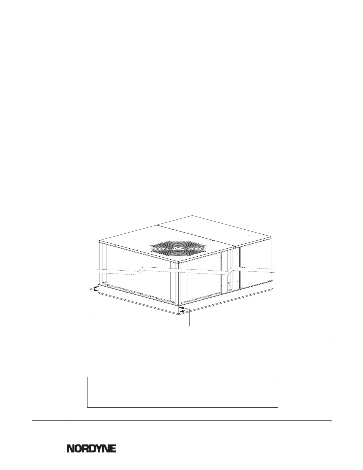
Figure 4
4. Install the second long rail cover by hooking the
offset fl anges of the rail cover into the fork truck
openings of the base rail, as above, holding it to the
right to clear the fl ange of the previously attached
rail cover. Then rotate the rail cover up against the
base pan wherein the upper edge of the rail cover is
above the base rail and below the side sheet metal.
(See Figure 3a above) slide the rail cover to the left
wherein the left edge of the rail cover is under the
right side fl ange of the previously attached rail cover.
(See Figure 3b above) Then where you had removed
the #10 x ½” Screws in Step 1 use the #10 x 1 ¼”
sheet metal screws to loosely secure the rail cover
to the unit base. – DO NOT TIGHTEN SCREWS.
5. Install the second short rail cover by hooking the offset
anges of the rail cover into the fork truck openings
of the base rail, as above, holding it to the right to
clear the fl ange of the previously attached rail cover.
Then rotate the rail cover up against the base pan
and over the left edge of the previously installed rail
cover, wherein the upper edge of the rail cover is
above the base rail and below the side sheet metal.
(See Figure 3a above) Slide the rail cover to the left
wherein the left edge of the rail cover is under the
right side fl ange of the previously attached rail cover.
(See Figure 3b above) Then where you had removed
the #10 x ½” screws in Step 1 use the #10 x 1 ¼”
sheet metal screws to loosely secure the rail cover
to the unit base. – DO NOT TIGHTEN SCREWS.
6. Secure the four corner fl anges of all the rail covers
to the underling rail covers with the eight (8) of the
screws you had removed and saved in Step 1 above.
(See Figure 4 below) Two (2) screws in each rail
cover corner fl anges. The two unused screws from
Step 1 above are extra and may be discarded.
7. The last step is to HAND TIGHTEN, the #10 1 ¼”
long sheet metal screws holding the rail covers to
the unit base. Note: Too much torque will distort the
rail covers.
Reuse Two (2) of the
#10 x 1/2” Long Screws
from Step 1 for Each Corner
  • Page 1 1
  • Page 2 2
  • Page 3 3
  • Page 4 4

Westinghouse R6GI Installation guide

Type
Installation guide
This manual is also suitable for

Ask a question and I''ll find the answer in the document

Finding information in a document is now easier with AI