
Table of Contents Rev. 4/5/2019 MTC MANUAL
Table of Contents Copyright 2019 Vestil Manufacturing Co. Page 1 of 9
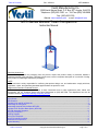
MTC-Series Manual Trash Compactors
Instruction Manual
Receiving instructions:
After delivery, remove the packaging from the product. Inspect the product closely to determine whether it
sustained damage during transport. If damage is discovered, record a complete description of it on the bill of lading.
If the product is undamaged, discard the packaging.
NOTE:
The end-user is solely responsible for confirming that product design, use, and maintenance comply with laws,
regulations, codes, and mandatory standards applied where the product is used.
Replacement Parts and Technical Service:
For answers to questions not addressed in these instructions and to order replacement parts, labels, and
accessories, call our Technical Service and Parts Department at (260) 665-7586. The department can also be
contacted online at http://www.vestilmfg.com/parts_info.htm
.
Table of Contents
Signal Words...…………………………………………………..……………………………………………………………… 2
Specifications………………………………..…………………….….………………………………………………………… 2
Exploded View and Bill of Materials…………………………….……………………………………………….………….... 3
Assembling the Compactor..……………………………………………………………………………………….. ………… 4, 5
Assembling Optional Roll-Out Base MTC-RB………………………………………………………………………………..5
Exploded View: Roll-Out Base Option (MTC-RB)………………………………………………………………………...… 6
MTC-RB Assembly Diagrams…………………………………………………………………………………………………. 6
Using the Compactor.……………..…………………………………………………………………………………………… 7
Labeling Diagram………………………………………………………………………………………………………………..7
Moving the Compactor…………..
…………………………………………………………................................................. 8
Record of Original Condition………………………………………………………………………………………………...... 8
Maintenance & Inspections……………………………………………………………………………………………………. 8
Limited Warranty…...…………………………………………………………………………………………………………… 9
Vestil Manufacturing Co.
2999 North Wayne Street, P.O. Box 507, Angola, IN 46703
Telephone: (260) 665-7586 -or- Toll Free (800) 348-0868
Fax: (260) 665-1339
Website: www.vestilmfg.com e-mail: inf[email protected]om

Table of Contents Rev. 4/5/2019 MTC MANUAL
Table of Contents Copyright 2019 Vestil Manufacturing Co. Page 2 of 9
Signal Words
This manual classifies personal injury risks and situations that might cause property damage with “Signal words”.
Signal words indicate the seriousness of injuries that might result if a particular act or omission occurs.
Identifies a hazardous situation which, if not avoided, WILL result in DEATH or
SERIOUS INJURY. Use of this signal word is limited to the most extreme situations.
Identifies a hazardous situation which, if not avoided, COULD result in DEATH or
SERIOUS INJURY.
Indicates a hazardous situation which, if not avoided, COULD result in MINOR or
MODERATE injury.
Identifies practices likely to result in product/property damage, such as operation that might
damage the boom.
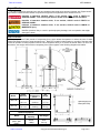
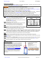
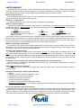
Specifications
The jack produces 7,000 pounds of compacting force, which allows the operator to reduce the size of waste
material and optimize space in waste storage drums. Both MTC models include wheels on one side of the base plate
to allow an operator to easily reposition the unit. Each compactor has a pin to secure the handle while it is not in use.
Dimensions, net weight, and maximum compacting force figures appear in the following diagrams and tables.
Model
Platen
Diameter
Maximum
Compacting
Force
Net
Weight
MTC-30
17” 7000 lb. 158 lb.
43.2 cm ~3182 kg 71.7 kg
MTC-55
21”
7000 lb.
167 lb.
53.3 cm
~3182 kg
75.9 kg
Optional Equipment
Model
Roll-Out Load
Capacity
Net Weight
MTC-RB
(ROLL-OUT
BASE)
800 lb.
~364kg
58 lb.
26.1 kg
Optional Roll-Out
Base (MTC-RB)

Table of Contents Rev. 4/5/2019 MTC MANUAL
Table of Contents Copyright 2019 Vestil Manufacturing Co. Page 3 of 9
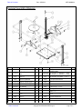
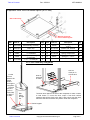
Exploded
View & Bill of Materials
Item Part no. Description Qty. Item Part no. Description Qty.
1 22-514-018 Weldment, base plate 1 9 22-113-004 Spacer, jack
2
2 16-132-225
2” x
7
/
8
” x
1
/
4
” bore rubber
wheel
2 10
22-014-049
22-014-050
Compactor platen:
MTC-30 (16 lb.; 17” diameter x
1
/
4
” thick)
MTC-55 (25 lb.; 21” diameter x
1
/
4
” thick)
1
1
3 37018
1
/
4
” – 20 UNC zinc-plated
Nylock nut
2 11 11207 Bolt, HHCS #2, zinc plated,
1
/
2
”-13x1
1
/
4
” 12
4 11009
1
/
4
” – 20 UNC x 1
1
/
2
” #2
HHCS zinc-plated bolt
2 12 37030
1
/
2
”-13 Nylon insert lock nut 14
5 22-514-019 Weldment, vertical support 2 13 93405
Socket head cap screw, zinc plated,
1
/
2
”-
13x1”
2
6 22-016-024 Bracket, front jack support 2 14 99-112-006 Pin, clevis 1
7 22-543-001 Jack assembly 1 15 45286 #1 hitch pin clip,
1
/
8
” x 2
5
/
8
” 1
7.1 22-043-001 Farm jack 1 16 07-025-005 Handle grip, black rubber, 6” 1
7.2 22-146-003 Spring, compression 2 17 21259
Bolt, carriage, gr. A, zinc finish,
5
/
16
”-
18UNC x 1
1
/
2
”
3
7.3 64133
Spring pin, plain finish,
3
/
16
”x1”
2 18 37021
Nylon insert lock nut, gr. 2, zinc finish,
5
/
16
”-18
3
7.4 33088
Washer, carbon steel, zinc
finish,
9
/
16
”
2 19 37032
1
/
2
” Nylon insert jam nut 2
7.5 22-612-003 Weldment, pin with handle 2 20 15221
1
/
2
”-13x4
1
/
2
” bolt, HHCS, GR. 8, zinc-plated
1
8 22-016-029 Jack center support 1 21 11221
1
/
2
”-13x4
1
/
2
” bolt, hex head 1

Table of Contents Rev. 4/5/2019 MTC MANUAL
Table of Contents Copyright 2019 Vestil Manufacturing Co. Page 4 of 9
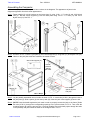
Assembling the Compactor
Numbers in parentheses correspond to item numbers in the diagrams. The appearance of parts in the
diagrams might differ from their actual appearances.
Step 1: Fasten wheels (2) to their brackets on the base plate (1) using ¼-20 x 1 ½” bolts (4) and ¼-20 Nylock
nuts (3). Bolt the vertical supports (5) onto the base plate using 1/2-13 x 1 ¼” bolts (11) and 1/2-13
Nylock nuts (12). See FIG. 1.
Step 2: As shown in FIG. 2, fasten a jack plate (6) onto vertical supports (5) using bolts (11) and Nylock nuts (12).
Labels on the jack plate must face outward to be visible to users.
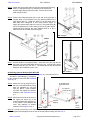
Step 3: Lay the partially assembled unit on its side as shown in FIG. 3. Insert bolts (20 & 21) through the holes in
the jack plate (6). Slide a spacer (9) onto the top bolt (20). Insert the jack center support (8) into the slot.
Step 4: [NOTE: Press the handle against the jack mast in order to properly connect the jack to the frame.] Guide
the bolts (20 & 21) through the corresponding openings in the jack as shown in FIG. 4. Then, slide the
remaining spacer (9) onto the top bolt (20). If correctly installed, the top bolt will project through the holes
in the jack body and jack handle as shown in the enlarged view in FIG. 4.
FIG. 1: Step 1
FIG. 2: Step 2
FIG. 3: Step 3
FIG. 4: Step 4
Jack center support (8)
top
Put another
spacer (9) onto
bolt (20)
Spacer (9)
Handle
pressed
against
jack mast

Table of Contents Rev. 4/5/2019 MTC MANUAL
Table of Contents Copyright 2019 Vestil Manufacturing Co. Page 5 of 9
Step 5: Fasten the second jack plate (6) onto the vertical supports using
bolts (11) and Nylock nuts (12). Make sure the jack center
support aligns with the slot in the plate. Put lock nuts on the
ends of bolts 20 & 21.
Step 6: Connect the compactor plate (10) to the end of the jack with 3
carriage bolts (17) and Nylock nuts (18). Warning labels on the
plate should face up. Install two bolts (13) in the holes in the
base plate that correspond to your drum volume (55gal. or
30gal.) and secure them with lock nuts (12). The inside holes (B)
are for 30 gallon drums. Outer holes (A) are for 55 gallon drums.
Install both bolts through the same labeled holes (A or B) in
either the front or the back of the base plate.
Step 7: Put the handle in an upright position. Insert the clevis pin (14) into the
top holes of the jack plates when unit is not in use. Lock the pin in place
with the hitch clip (15). See FIG. 7. The handle should also be secured
whenever the compactor is not in use.
Assembling Optional Roll-Out Base MTC-RB
Refer to the Exploded View and Assembly Diagrams on p. 6 as well as FIG. 8.
Numbers in parentheses () correspond
to item numbers in the MTC-RB Exploded
View on p. 6.
Step 8: Attach one end of each link (2) to
the slots in the MTD-RD tray using
bolts (3), washers (4), and lock
nuts (5). NOTE: Three washers
are used. Pay attention to washer
locations in the
Exploded View on
p. 6.
Step 9: Attach the free ends of the links to
the upper bolt holes (A) in the
vertical supports with hardware (3,
4, & 5). NOTE: Three washers are
used. Pay attention to washer
locations in the
diagram on p. 6.
Step 10: Lock the roll-out tray to the frame. Insert clevis pins (6) through the bottom holes (B) of the vertical
supports and through the hole on the roll-out tray when moving unit. See FIG. 8.
FIG. 7: Step 7
FIG. 5: Step 5
FIG. 6: Step 6
FIG. 8: Step 8
B: Hole for
clevis pin (6)
Hole
for
clevis
pin (6)
Vertical
support
A
B
A: Attach link to
upper bolt hole
A
B
A
B
B
B
A
A
BACK
FRONT

Table of Contents Rev. 4/5/2019 MTC MANUAL
Table of Contents Copyright 2019 Vestil Manufacturing Co. Page 6 of 9
Exploded View: Roll-Out Base Option (MTC-RB)
Pin the
roll-out
base to the
frame
before
moving the
compactor.
Remove
the pins
(one on
each side)
to allow it
to slide.
The drum deck slides to the side of the compactor to make it easier
to load drums. To move the deck, unpin it from both vertical
supports and pull the deck to the side. Load a drum onto the deck
and move the drum and deck into position under the compactor.
Hole for
clevis pin
in frame
Hole for
clevis pin in
roll-out deck
Bolt
slides
through
slot
Item Part no. Description Qty. Item Part no. Description Qty.
1 22-514-020 Subassembly, deck/tray 1 7 45286
#11 hitch pin clip,
1
/
8
”x2
5
/
8
”
2
2 22-016-077 Frame, link 2 8 22-114-001 Washer, flat, finished 8
3 11007
1
/
4
”-20UNCx1
1
/
4
” hex bolt 4 9 22-027-001 Ball transfer, machined 4
4 33006
5
/
16
” flat washer 12 10 22-146-004 Spring, compression 4
5 37018
1
/
4
”-20, Nylon lock nut, grade
2, zinc finish
4 11 64257 Spring pin,
1
/
4
”x2
1
/
2
” 4
6 21-112-003
1
/
2
” x 1
15
/
16
” clevis pin 2
Vertical support
Attach to upper bolt
hole in vertical support
MTC-RB Assembly Diagrams
Slot in side of tray

Table of Contents Rev. 4/5/2019 MTC MANUAL
Table of Contents Copyright 2019 Vestil Manufacturing Co. Page 7 of 9
Using the Compactor
Read the entire manual before putting the compactor into service. If questions remain after you finish
reading the manual, contact Technical Service for answers.
Improper operation could result in serious personal injuries.
• DO NOT compact contents inside a drum that is damaged. E.g. severely rusted or corroded
• ALWAYS inspect the compactor and the drum BEFORE each use. Follow the Maintenance & Inspections
procedures provided on p. 8. Only use the compactor if it is in Original Condition.
• The drum might be too heavy for 1 person to maneuver. Ask someone to help you.
• NEVER modify the compactor in any way without express, written approval from Vestil. Unapproved
modifications automatically void the Limited Warranty and might make the compactor unsafe to use.
• Keep fingers and hands away from the drum rim and the compactor platen while it is moving.
• DO NOT stand directly in line with the handle. DO NOT lean over the handle while operating the jack. The
handle could recoil upwards out of your hands if the handle is not pressed all the way down during each stroke.
Step A: Free the jack handle by removing the storage pin (14). See
FIG. 7 on p. 5. Turn the jack direction levers to UP position
and fully raise the compactor plate. Refer to FIG. 9
MTC-RB units: Remove the pins securing the roll-out tray to
the frame. See FIG. 8 on p. 5.
Step B: Center the drum under the platen.
MTC-RB units: Roll out tray. Place drum on tray and push
the tray under jack. Center drum under the platen.
Step C: Turn the jack direction levers to the DOWN position.
Step D: Stand to one side of the jack handle. Lower the compactor
platen by moving the handle up and down. Fully raise and fully lower the handle. This is necessary for
the ratchet mechanisms of the jack to properly interact.
Step E: Lower the compactor platen into contact with the waste material. Continue ratcheting the jack until the
desired degree of compaction is achieved. NOTE: To achieve optimum compression, compact waste
materials frequently. Materials will not compact as completely or easily if the drum is full or mostly full.
Step F: Once compaction is adequate, turn both direction levers to the UP position.
Step G: Raise the compactor platen high enough to remove the drum or until the platen is fully raised.
Step H: Put the jack handle in the storage position and secure it with the clevis pin (11) and hitch pin (12). See
FIG. 7 on p. 5.
Step I: Remove the drum. MTC-RB model: Pull the drum out from under the platen. Remove the drum. Push the
tray back onto the base plate. Be certain to reinstall the clevis pins and hitch pins. See FIG. 8 on p. 5.
Step J: Store the compactor in a dry, indoor location. Keep the device dry at all times.
DOWN UP
FIG. 9: Direction Selection Levers
Labeling Diagram
The unit should be labeled as shown in the diagram.
However, label appearance, content, and location are
subject to change so your product might not be labeled
exactly as shown. Replace all labels that are damaged,
missing, or not easily readable (e.g. faded). Order
replacement labels by contacting Technical Service
online at http://www.vestilmfg.com/parts_info.htm.
Alternatively, you may request replacement parts and
service by calling (260) 665-7586 and asking the
operator to connect you to the Technical Service
Department.
A: Data label (Model, Serial #,
Capacity, Date)
B
A
B: Label 208 (both jack plates; on
top of platen; on jack handle)

Table of Contents Rev. 4/5/2019 MTC MANUAL
Table of Contents Copyright 2019 Vestil Manufacturing Co. Page 8 of 9
Moving the Compactor
Carelessness while moving the compactor might result in personal injuries.
• DO NOT move the compactor while it is loaded. Unload the compactor before moving it.
• Secure the jack handle in the storage position with clevis pin & hitch pin before moving the compactor. See
Step 7 on p. 5.
• [Units with MTC-RB] Secure the roll-out tray as described in Step 10 on p. 5 before moving the unit.
Step 1: Stand to the side of the unit where the wheels are mounted.
Grasp the jack and jack handle. See FIG. 10.
Step 2: Tilt the unit towards you until the wheels contact the ground.
Step 3: Push the compactor to desired location. Slowly lower the
raised side until it rests on the ground.
Record of Original Condition
Make a record of the unit in its original condition before putting it
into service. Thoroughly photograph the assembled compactor from
all sides. Include close range photos of the following: Each label applied to the unit; the direction selection levers;
all fasteners and pins; the platen; the jack plates; and the base plate. Raise and lower the platen. Describe the
motion of the jack as well as how it sounds while the ratchet mechanism operates. Collate all documentation and
photographs. This record establishes “original condition”. Compare the results of every inspection to this record.
Repair or replace all parts that no longer are in original condition. Purely cosmetic changes are not changes from
original condition. However, touchup paint should be applied to all areas where the surface coating is damaged as
soon as the damage occurs.
Maintenance & Inspections
Regular maintenance is essential to keep the compactor in original condition.
Maintenance:
Implement a maintenance program to ensure that the compactor remains in original condition.
Step 1: Tag the compactor, “Out of Service.”
Step 2: Conduct the appropriate inspection (Before each use or Periodic).
Step 3: Perform all other necessary adjustments and/or repairs. DO NOT use the compactor until it has been
repaired with approved replacement parts. Contact Technical Service for assistance if you discover conditions
during an inspection that are not addressed in this manual or with any other questions that arise during use or
inspections.
Step 4: Make a dated record of all repairs, adjustments and replacements.
Inspections:
A. Before each use — Examine the jack for either of the following:
1. Frame damage/deformation;
2. Abnormal function: ratchet the compactor plate up and down
B. Periodic — Inspect the following components at least once per month for corrosion, damage, excessive
wear or rusting, and noisy or rough operation:
1. Compactor platen
2. Jack front and back plates
3. Base plate
4. Jack and jack handle
5. Fasteners (bolts, nuts, clevis pins and hitch pin)
6. Labels. See Labeling Diagram on p. 6.
FIG. 10 Moving Unit
wheel

Table of Contents Rev. 4/5/2019 MTC MANUAL
Table of Contents Copyright 2019 Vestil Manufacturing Co. Page 9 of 9
LIMITED WARRANTY
Vestil Manufacturing Corporation (“Vestil”) warrants this product to be free of defects in material and workmanship
during the warranty period. Our warranty obligation is to provide a replacement for a defective, original part covered
by the warranty after we receive a proper request from the Warrantee (you) for warranty service.
Who may request service?
Only a warrantee may request service. You are a warrantee if you purchased the product from Vestil or from an
authorized distributor AND Vestil has been fully paid.
Definition of “original part”?
An original part is a part used to make the product as shipped to the Warrantee.
What is a “proper request”?
A request for warranty service is proper if Vestil receives: 1) a photocopy of the Customer Invoice that displays the
shipping date; AND 2) a written request for warranty service including your name and phone number. Send requests
by one of the following methods:
US Mail Fax Email
Vestil Manufacturing Corporation (260) 665-1339 info@vestil.com
2999 North Wayne Street, PO Box 507 Phone Enter “Warranty service request”
Angola, IN 46703 (260) 665-7586 in subject field.
In the written request, list the parts believed to be defective and include the address where replacements should be
delivered. After Vestil receives your request for warranty service, an authorized representative will contact you to
determine whether your claim is covered by the warranty. Before providing warranty service, Vestil will require you to
send the entire product, or just the defective part (or parts), to its facility in Angola, IN.
What is covered under the warranty?
The warranty covers defects in the following original, dynamic parts: motors, hydraulic pumps, motor controllers,
and cylinders. It also covers defects in original parts that wear under normal usage conditions (“wearing parts”), such
as bearings, hoses, wheels, seals, brushes, and batteries.
How long is the warranty period?
The warranty period for original dynamic components is 30 days. For wearing parts, the warranty period is 30
days. Both warranty periods begin on the date Vestil ships the product to the Warrantee. If the product was
purchased from an authorized distributor, the periods begin when the distributor ships the product. Vestil may, at its
sole discretion, extend a warranty period for products shipped from authorized distributors by up to 30 days to account
for shipping time.
If a defective part is covered by the warranty, what will Vestil do to correct the problem?
Vestil will provide an appropriate replacement for any covered part. An authorized representative of Vestil will
contact you to discuss your claim.
What is not covered by the warranty?
The Warrantee (you) is responsible for paying labor costs and freight costs to return the product to Vestil for
warranty service.
Events that automatically void this Limited Warranty.
• Misuse;
• Negligent assembly, installation, operation or repair;
• Installation/use in corrosive environments;
• Inadequate or improper maintenance;
• Damage sustained during shipping;
• Collisions or other accidents that damage the product;
• Unauthorized modifications: Do not modify the product IN ANY WAY without first receiving written authorization
from Vestil.
Do any other warranties apply to the product?
Vestil Manufacturing Corp. makes no other express warranties. All implied warranties are disclaimed to the extent
allowed by law. Any implied warranty not disclaimed is limited in scope to the terms of this Limited Warranty. Vestil
makes no warranty or representation that this product complies with any state or local design, performance, or safety
code or standard. Noncompliance with any such code or standard is not a defect in material or workmanship.
-
 1
1
-
 2
2
-
 3
3
-
 4
4
-
 5
5
-
 6
6
-
 7
7
-
 8
8
-
 9
9


Ask a question and I''ll find the answer in the document
Finding information in a document is now easier with AI
Related papers
-
Vestil TH-CART Owner's manual
-
-
-
-
-
-
-
-
-