
SmartTrak
®
100
Profibus DP
Instruction Manual
Profibus DP Device Specification for SmartTrak
®
Models: 100, 101 and 140
Mass Flow Meters & Controllers
Part Number: IM-100ProfibusDP Rev.V1
May 2013

GLOBAL SUPPORT LOCATIONS: WE ARE HERE TO HELP!
CORPORATE HEADQUARTERS
5 Harris Court, Building L Monterey, CA 93940
Phone (831) 373-0200 (800) 866-0200 Fax (831) 373-4402
www.sierrainstruments.com
EUROPE HEADQUARTERS
Bijlmansweid 2 1934RE Egmond aan den Hoef
The Netherlands
Phone +31 72 5071400 Fax +31 72 5071401
ASIA HEADQUARTERS
Second Floor Building 5, Senpu Industrial Park
25 Hangdu Road Hangtou Town
Pu Dong New District, Shanghai, P.R. China
Postal Code 201316
Phone: + 8621 5879 8521 Fax: +8621 5879 8586
© COPYRIGHT SIERRA INSTRUMENTS 2013
No part of this publication may be copied or distributed, transmitted, transcribed, stored in a retrieval system, or translated into any
human or computer language, in any form or by any means, electronic, mechanical, manual, or otherwise, or disclosed to third parties
without the express written permission of Sierra Instruments. The information contained in this manual is subject to change without
notice.
TRADEMARKS
SmartTrak
®
is a trademark of Sierra Instruments, Inc. Other product and company names listed in this manual are trademarks or trade
names of their respective manufacturers.

Warnings and Cautions
Note and Safety Information
We use caution and warning statements throughout this book to draw
your attention to important
information.
Warning!
Caution!
This statement appears with information that
is important to protect people and equipment
from damage. Pay very close attention to all
warnings that apply to your application.
This statement appears with information that is
important for protecting your equipment and
performance. Read and follow all cautions that
apply to your application.
Warning!
Agency approval for hazardous location installations varies between flow meter models. Consult the flow meter
nameplate for specific flow meter approvals before any hazardous location installation.
Warning!
All wiring procedures must be performed with the power off.
Warning!
To avoid potential electric shock, follow National Electric Code safety practices or your local code when wiring this unit
to a power source and to peripheral devices. Failure to do so could result in injury or death. All AC power connections must be in
accordance with published CE directives.
Warning!
Do not power the flow meter with the sensor remote (if applicable) wires disconnected. This could cause over-heating of the
sensors and/or damage to the electronics.
Warning!
Before attempting any flow meter repair, verify that the line is de-pressurized.
Warning!
Always remove main power before disassembling any part of the mass flow meter/controller.
Caution!
Before making adjustments to the device, verify the flow meter/controller is not actively monitoring or reporting to any
master control system. Adjustments to the electronics will cause direct changes to flow control settings.
Caution!
When using toxic or corrosive gases, purge the line with inert gas for a minimum of four hours at full gas flow
before installing the meter.
Caution!
The AC wire insulation temperature rating must meet or exceed 80°C (176°F).
Caution!
Printed circuit boards are sensitive to electrostatic discharge. To avoid damaging the board, follow these
precautions to minimize the risk of damage:
before handling the assembly, discharge your body by touching a grounded, metal object
handle all cards by their edges unless otherwise required
when possible, use grounded electrostatic discharge wrist straps when handling sensitive components
!
!

4
Receipt of System Components
When receiving a Sierra mass flow meter, carefully check the outside
packing
carton for
damage incurred in shipment. If the carton is damaged, notify the local carrier and submit a
report to the factory or distributor. Remove the packing slip and check that all ordered
components are present. Make sure any spare parts or accessories are not
discarded with
the packing material. Do not return any equipment to
the factory without first contacting
Sierra Customer Service
.
Technical Assistance
If you encounter a problem with your flow meter, review the configuration information for
each step of the installation, operation, and
setup procedures. Verify that your settings
and adjustments are consistent with factory recommendations. Installation and
troubleshooting information can be found in the SmartTrak 100 Series manual.
If the problem persists after following the troubleshooting procedures
outlined in the
SmartTrak 100 Series manual, contact Sierra Instruments by fax or by E-mail
(see inside
front cover). For urgent phone support you may call (800)
866-0200 or (831) 373-0200
between 8:00 a.m. and 5:00 p.m. PST. In
Europe, contact Sierra Instruments Europe at
+31
(0)72-5071400
. In the Asia-Pacific region, contact Sierra Instruments Asia at +
86-21-
58798521.
When contacting Technical Support, make sure to include this information:
The flow range, serial number, and Sierra order number (all
marked on
the meter nameplate)
The software version (visible at start up)
The problem you are encountering and any corrective action
taken
Application information (gas, pressure, temperature and piping
configuration)

5
Table of Contents
2
Chapter 1: Introduction ................................................................................................................... 6
Set Up Quick Step Plan ............................................................................................................................... 6
Chapter 2: Field Bus Installation .................................................................................................... 7
Fieldbus Connector ..................................................................................................................................... 7
Cable ........................................................................................................................................................... 8
Termination .................................................................................................................................................. 8
Status LED’s ................................................................................................................................................ 8
Slave Address ............................................................................................................................................. 9
Dip Switch ................................................................................................................................................... 9
Server Assigned Address ......................................................................................................................... 10
Set Address (126) ..................................................................................................................................... 10
Chapter 3: Configuration .............................................................................................................. 11
GSD File .................................................................................................................................................... 11
Cyclic Data Overview ................................................................................................................................ 11
Cyclic Data Explained ................................................................................................................................ 12
Chapter 4: Sycon Software ........................................................................................................... 15
Import Device Description (GSD) Files ...................................................................................................... 15
Configure A Slave ...................................................................................................................................... 16
Create A New Document And Insert A Master: ......................................................................................... 16
Auto Addressing ........................................................................................................................................ 17
Insert A Slave To The System. .................................................................................................................. 18
Download Configuration ............................................................................................................................ 19
Check The Configuration ........................................................................................................................... 21
Kepserver OPC Software ......................................................................................................................... 23
GSD File Text And Cert ............................................................................................................................. 30

6
Chapter 1: Introduction
This manual will explain how to add a Sierra flow meter or controller equipped with Profibus DP to
your network. This interface allows access to all relevant data available in the flow meter.
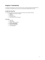
Set Up Quick Step Plan
To successfully add the flow meter to a Profibus DP network you need the following:
Profibus network with a DP master
GSD file
Bitmap files
Connection cables
Power supply (for the flow meter)
Setup steps:
Load GSD
Copy bitmaps
Add slave device to system
Set slave configuration
Set slave station address
Download configuration
Test configuration

7
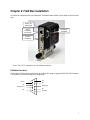
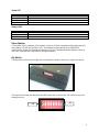
Chapter 2: Field Bus Installation
All electrical connections for your SmartTrak
®
Instrument and Profibus DP are made on the left (inlet)
side:
Note: The CAT 5 connector is not an Ethernet connector
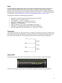
Fieldbus Connector
The Profibus DP network is connected to the Profibus DP using an approved Profi-DP DB9 connector.
The connector has the following pin configuration:
NC
1
NC
2
PB-B (red)
3
NC
4
PB-GND
5
PB-5V
6
NC
7
PB-A (green)
8
NC
9
Power “On”
Green Light
CAT 5
Connector
(Pilot Module)
15-Pin D
Connector
Profibus DP
Connector

8
Cable
Profibus cables are shielded twisted-pair copper cables which differ from each other in the type of
wire (fixed/flexible) and/or sheath. The two inner cores of a Profibus cable have green and red
insulation. The specifications in this chapter are primarily intended to provide a general introduction
and describe the cable properties to be considered (see also IEC 61784-5-3). A Profibus wiring guide
can be found at: http://verwertraining.com/wp-content/uploads/InstallationGuideV9_2.pdf
The cable must conform to the following specifications:
Impedance: 150 Ohm (nominal) at frequencies from 3 to 20 MHz.
Cable capacitance: < 30 pF per meter.
Core diameter: > 0.34 mm², corresponds to AWG 22.
Cable type: twisted pair cable. 1x2 or 2x2 or 1x4 lines.
Resistance: < 110 Ohm per km.
Signal attenuation: max. 9 dB over total length of line section.
Shielding: CU shielding braid or shielding braid and shielding foil.
Max. Bus length: 200 m at 1500 Kbit/s, up to 1.2 km at 93.75 Kbit/s.
Termination
The Profibus physical layer is based on RS-485, and therefore termination resistors are needed at both
ends of the network. Many Profibus DB 9 connectors have built-in switchable terminators that can be
powered from the Profibus DP. The schematic below shows the internal wiring of a terminator:
Status LEDS
The interface has two multi-color LEDs mounted on top of the enclosure to indicate the status.
The left LED is used to show the status of the interface the right LED shows the network status.

9
Status LED
Status
Description
Flashing green/red
Initializing
Steady green
Device operational
Flashing red
Recoverable hardware failure
Steady red
Hardware failure – attention required
Network LED
Status
Description
Off
Not online – waiting for configuration
Steady green
Data exchange
Flashing red
Connection lost
Slave Address
The Profibus DP slave address of the interface can be set. Default instruments will be delivered with
slave address 126 (all DIP switches to off). This address has been agreed by the PROFIBUS
organization to be free for installing new devices to the bus. Changing the station address is done in
two ways, either through a dip switch or through the master.
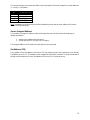
Dip Switch
The dip switch is located on the right side of the interface. Remove the cover to expose the switch:
The dip switch is binary encoded with the LSB (lowest bit) on the left side. The switch is only read
during power-up.
LSB
MSB

10
The switch becomes active when the slider is moved upwards. Here some examples of some addresses
(1 = on/up, 0 = off/down):
Address
ID
Dip Switch #
1 2 3 4 5 6 7 8
1
1|0|0|0|0|0|0|0
14
0|1|1|1|0|0|0|0
60
0|0|1|1|1|1|0|0
125
1|0|1|1|1|1|1|0
Note: An address set with the dip switch has the highest priority and the slave address will use this
address when powering up!
Server Assigned Address
It is possible to change the address of the unit through the server. Perform the following steps to
change the address:
1. Assign a new address from the server
2. Set the dip switch to 128 (pin 8 on) or higher.
The assigned address will be used each time that the unit is powered.
Set Address (126)
It is possible to force the address of the unit to 126. Set the dip switch to zero and power cycle the unit.
The address is set to 126. The address can be changed by the Master if needed. Do keep in mind that if
the dip switch remains set to zero, the address will be set to 126 at each power-up.

11
Chapter 3: Configuration
GSD File
Each Profibus DP instrument comes with its own GSD-file. The GSD file contains the instrument
specifications telling the master configuration software which facilities/features the instrument offers
to the Profibus system. The GSD file can be download from
http://www.sierrainstruments.com/userfiles/file/SIER0E12.GSD .
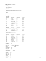
The GSD-file is a text-file containing:
Identification info:
o Model name: “SmartTrak 100S - Profibus”
o Vendor name: “Sierra Instruments Inc.”
o Identification number: 0x012E
o Bitmap device: “100S_dev”
o Bitmap diagnostics: “100S_dia”
o Bitmap SF: “100S_spf”
(Bitmap files are used in configuration software to indicate instrument status)
Revision numbers
Hardware characteristics:
o VPC3+C dependable properties
Software characteristics:
o Supported features of Profibus: Freeze, Sync, auto baud rate detection
Maximum bus data lengths
Size of used data buffers
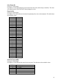
Cyclic Data Overview
The following table shows the cyclic input & output buffer supported by the device. The cyclic data is
in 2 Modules. Module 1 has 32 bytes in of process data in, and 24 bytes out. Module 2 has 14 bytes in
of device info. The actual data address will depend on preceding devices on your bus. The matrix
example below shows the actual data addresses, assuming the Profibus DP is the first device on your
Profibus network.
Incoming Cyclic Data (Module 1 slave to master)
Data
Address
Description
Size
(bytes)
Format
0
Flow
4
REAL
4
Set point
4
REAL
8
Valve mode
2
INT
10
Valve power
2
INT
12
User full scale
4
REAL
16
Factory full scale
4
REAL
20
Flow unit
2
INT
22
Set point source
2
INT
24
Gas span
4
REAL
28
Gas index
2
INT
30
Status
2
INT
32 bytes

12
Outgoing Cyclic Data (Module 1 master to slave)
Data
Address
Description
Size
(bytes)
Format
0
Set point
4
REAL
4
Valve mode
2
INT
6
User full scale
4
REAL
10
Flow unit
2
INT
12
Set point source
2
INT
14
Gas span
4
REAL
18
Gas index
2
INT
20
Zero unit
2
INT
22
Factory reset
2
INT
24 bytes
Device info: (Module 2 master to slave)
Data
Address
Description
Size
(bytes)
Format
32
Serial number
8
ASCII
40
Device type (set to 100)
2
INT
42
Firmware revision
4
REAL
14 bytes
Cyclic Data Explained
Flow (R):
Data type: 32 bit floating point also called REAL (LSB – MSB)
Description: The flow as measured by the instrument
Set Point (R/W):
Data type: 32 bit floating point (LSB – MSB)
Description: When using a controller the set point is shown. Writing to this register will set the set
point. When a set point is entered which is beyond the full scale of the instrument then the set point
will be changed automatically to the full scale value.
User Full Scale (R/W):
Data type: 32 bit floating point (LSB – MSB)
Description: The user full scale value allows you to re-range the instrument. Any value between 50%
and 100% of the factory full scale is allowed. The new value will also redefine the analog outputs of
the instrument (when used). The 20mA/5 VDC will represent the new full scale value.
Factory Full Scale (R):
Data type: 32 bit floating point (LSB – MSB)
Description: Factory full scale value of the instrument.
Valve Mode (R/W):
Data type: 16 bit integer
Description: Mode at which the valve of the controller will operate. The table shows the available
values:
Value
Mode
1
Automatic
2
Closed
3
Purge

13
Valve Power (R):
Data type: 16 bit integer
Description: Value representing the power injected into the value (when using a controller). The value
will range between 0 and 3200 (4095 when purging the valve).
Flow Unit (R):
Data type: 16 bit integer
Description: The value indicates the selected engineering flow unit on the instrument. The table shows
the available values:
Value
Unit
1
Scc/s
2
Scc/m
3
Scc/h
4
Ncc/s
5
Ncc/m
6
Ncc/h
7
SCF/s
8
SCF/m
9
SCF/h
10
NM3/s
11
NM3/m
12
NM3/h
13
SM3/s
14
SM3/m
15
SM3/h
16
Sl/s
17
Sl/m
18
Sl/h
19
Nl/s
20
Nl/m
21
Nl/h
22
g/s
23
g/m
24
g/h
25
Kg/s
26
Kg/m
27
Kg/h
28
Lb/s
29
Lb/m
30
Lb/h
Set Point Source (R/W):
Data type: 16 bit integer
Description: Value indicates the source for the set point. The table shows the available values:
Value
Source
1
Digital (Profibus)
2
0 – 5 volts
3
0 – 10 volts
4
1 – 5 volts
5
4 – 20 mA
6
0 – 20 mA (SmartTrak 2 or higher)

14
CAUTION!
Select digital as source when the set point needs to be controlled through the network.
The other setting are for analog inputs on the DB15 connector
Gas Span (R/W):
Data type: 32 bit floating point (LSB – MSB)
Description: The gas span value allows you to linearly adjust the calibration of each available gas,
factory value is 1 and can range between 0.5 and 2.0.
Gas Index (R/W):
Data type: 16 bit integer
Description: Value shows which gas is selected on the instrument. Value can range between 1 and 10.
Zero Unit (R/W):
Data type: 16 bit integer
Description: Writing the value 0xA5 to this register will set the zero the instrument (not available on
the SmartTrak 1). See the SmartTrak 2 manual for more information.
Factory Reset (R/W):
Data type: 16 bit integer
Description: Writing the value 0xA5 to this register will reset all custom settings to factory defaults.
The zero value and gas span values are also reset.
Serial Number (R):
Data type: 16 bits ASCII
Description: Serial number of the instrument expressed as an eight character string.
Firmware Revision (R):
Data type: 32 bit floating point (LSB – MSB)
Description: Firmware revision number of the instrument.
Device Type (R):
Data type: 16 bit integer
Description: Number which represents the flow meter series (100 = 100S, 640 = 640S)
Status (R):
Data type: 16 bit integer
Description: Status indicates if the quality of the data in the registers (0 = bad, 1 = good).
!

15
Chapter 4: Sycon software
Sycon is a tool for the configuration of a Fieldbus network using a Hilscher CIF50-PB master. You
may be using a different configuration software and hardware Master, however, you will need to
accomplish the same functions. No specific slave DTMs of the Profibus DP are available.
Online diagnostic indicators and auto-scan function for the reading of network participants assist in the
commissioning of the network.
This guide will explain step by step how to configure the system to support various Profibus slaves on
a Hilscher CIF50-PB master.
Before starting make sure that the necessary device description files (GSD and bit maps) are available
in your device catalog. These are available on our web site.
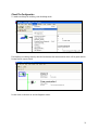
Import Device Description (GSD) Files
In order to use a fieldbus device its properties need to be added to the CIF50-PB Master. This is done
by importing the device description files (GSD) into Sycon.
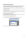
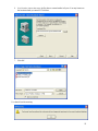
Start Sycon and create a new document (File -> New)
A dialog window appears asking to select a fieldbus. For this example select Profibus:
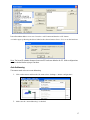
The main window is loaded. Go to the file menu and select “Copy GSD”:

16
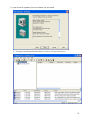
Locate the desired GSD file and load it. You will also be prompted to “import the corresponding
bitmap files”, click Yes. Load all 3 bitmap files. The GSD data is added to the Sycon library but it
isn’t available yet. Quit the program and restart it to refresh the catalog.
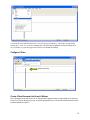
Configure A Slave
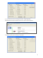
Create A New Document And Insert A Master:
Place the master at the top of the line. A dialog window appears where a master needs to be selected
from a list. The list shows every type of master supported by Sycon. Select the Profibus master which
has been installed on the PC:
Add master here

17
Leave the station address set to zero. Press the “Add” button and then the “OK” button.
A window pops up showing the driver linked to the selected master. Press “Yes” to use the hardware.
Note: The board ID number changes when extra PCI cards are added to the PC. Older configurations
must be checked before trying to run them.
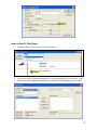
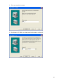
Auto Addressing
The master needs to be set to auto addressing.
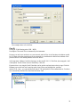
1. Click on the master and from the file menu select “Settings -> Master configuration”:
2. Make sure the “Auto addressing” is checked:

18
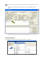
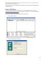
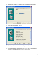
Insert a Slave To The System
1. File menu: Insert -> Slave. Place it below the master:
2. Set the slave filter to “Sierra Instruments Inc.” Select the desired GSD file, press the “Add”
button, set the slave address and description to match the slave and press the “OK” button.
Add slave here

19
Note: If no slave device appears in the window then the GSD file hasn’t been copied into the Sycon
catalog.
3. Double click on the added slave in the main window. The slave configuration window
appears:
4. Select the desired modules by double clicking on the module name. Press the “OK” button.
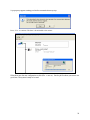
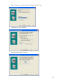
Download Configuration
The configuration needs to be downloaded to the master (Online -> Download):

20
A pop-up may appear warning you that the communication may stop:
Press “Yes” to continue. The data is downloaded to the master:
When done save the new configuration to disk (File -> save as). Put the .pb file where your server can
get it later. The system is ready to be used.
Page is loading ...
Page is loading ...
Page is loading ...
Page is loading ...
Page is loading ...
Page is loading ...
Page is loading ...
Page is loading ...
Page is loading ...
Page is loading ...
Page is loading ...
Page is loading ...
-
 1
1
-
 2
2
-
 3
3
-
 4
4
-
 5
5
-
 6
6
-
 7
7
-
 8
8
-
 9
9
-
 10
10
-
 11
11
-
 12
12
-
 13
13
-
 14
14
-
 15
15
-
 16
16
-
 17
17
-
 18
18
-
 19
19
-
 20
20
-
 21
21
-
 22
22
-
 23
23
-
 24
24
-
 25
25
-
 26
26
-
 27
27
-
 28
28
-
 29
29
-
 30
30
-
 31
31
-
 32
32


Sierra SmartTrak 100 Profibus DP User manual
- Type
- User manual
- This manual is also suitable for
Ask a question and I''ll find the answer in the document
Finding information in a document is now easier with AI
Related papers
-
Sierra 140 SmartTrak User manual
-
-
-
-
-
-
-
-
-
Other documents
-
ICP GW-7553 User manual
-
ICP DAS USA I-7550E User manual
-
Eurotherm T630 User guide
-
Eurotherm 4103/4100G 100mm Chart Recorders Owner's manual
-
-
-
Schneider Electric LUFP7 User manual
-
-
-