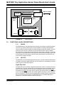
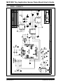
Microchip Technology MCP355X is a feature-rich 10-bit, 50ksps, single-channel Analog-to-Digital Converter (ADC) with an integrated 2.048V reference, ideal for low power applications. The MCP355X is well suited for low power data acquisition and low power sensor applications. It offers a low-power shutdown mode, and operates from a single 2.7V to 5.5V supply.
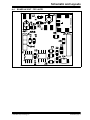
Microchip Technology MCP355X is a feature-rich 10-bit, 50ksps, single-channel Analog-to-Digital Converter (ADC) with an integrated 2.048V reference, ideal for low power applications. The MCP355X is well suited for low power data acquisition and low power sensor applications. It offers a low-power shutdown mode, and operates from a single 2.7V to 5.5V supply.


-
 1
1
-
 2
2
-
 3
3
-
 4
4
-
 5
5
-
 6
6
-
 7
7
-
 8
8
-
 9
9
-
 10
10
-
 11
11
-
 12
12
-
 13
13
-
 14
14
-
 15
15
-
 16
16
-
 17
17
-
 18
18
-
 19
19
-
 20
20
-
 21
21


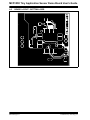
Microchip Technology MCP355X is a feature-rich 10-bit, 50ksps, single-channel Analog-to-Digital Converter (ADC) with an integrated 2.048V reference, ideal for low power applications. The MCP355X is well suited for low power data acquisition and low power sensor applications. It offers a low-power shutdown mode, and operates from a single 2.7V to 5.5V supply.
Ask a question and I''ll find the answer in the document
Finding information in a document is now easier with AI
Related papers
-
Microchip Technology MCP73855 User manual
-
-
-
-
-
-
-
-
-
Other documents
-
Panasonic FY350ZDY8R Operating instructions
-
 Arizona 17 User manual
-
Texas Instruments Analog Front-End Design for ECG Systems Using Delta-Sigma ADCs (Rev. A) Application notes
-
Embertec Emberplug AV Operating instructions
-
 SCK Direct, Inc. SmartSensor Installation guide
-
Campbell Scientific CD294 Owner's manual
-
MICROCHIP MCP1630 1A User guide
-
Victron energy SmartShunt Owner's manual
-
-
AMS Eval Kit AS7024 Quick start guide

