
ANTI-LOCK BRAKING SYSTEM
(ABS) AND ELECTRONIC
STABILITY CONTROLS (ESC):
FOR E VERSION ECUs
MAINTENANCE MANUAL

Service Notes
Information contained in this publication was in effect at the time the publication
was approved for printing and is subject to change without notice or liability.
WABCO reserves the right to revise the information presented or to discontinue the
production of parts described at any time.
WABCO Maintenance Manual MM-0112 (Revised 07-18)
About This Manual
This manual contains maintenance procedures for WABCO’s
Anti-Lock Braking System (ABS), Roll Stability System (RSC),
Electronic Stability Controls (ESC) and Hill Start Aid (HSA).
Before You Begin
1. Read and understand all instructions and procedures before
you begin to service components.
2. Read and observe all Warning and Caution hazard alert
messages in this publication. They provide information that can
help prevent serious personal injury, damage to components,
or both.
3. Follow your company’s maintenance and service, installation
and diagnostics guidelines.
4. Use special tools when required to help avoid serious personal
injury and damage to components.
Hazard Alert Messages and Torque
Symbols
Read and observe all Warning and Caution hazard alert messages in
this publication. They provide information that can help prevent
serious personal injury, damage to components, or both.
WARNING
A Warning alerts you to an instruction or procedure that you
must follow exactly to avoid serious personal injury and
damage to components.
CAUTION
A Caution alerts you to an instruction or procedure that you
must follow exactly to avoid damage to components.
@ This symbol alerts you to tighten fasteners to a specified torque
value.
WARNING
To prevent serious personal injury, always wear safe eye
protection when you perform vehicle maintenance or service.
Release all air from the air systems before you remove any
components. Pressurized air can cause serious personal
injury.
CAUTION
When welding on an ABS- or ABS/ATC-equipped vehicle is
necessary, disconnect the power connector from the ECU to
prevent damage to the electrical system and ABS/ATC
components.
How to Obtain Additional Maintenance,
Service and Product Information
Visit wabco-auto.com to access and order additional information.
Contact WABCO North America Customer Care at 855-228-3203
(United States and Canada); 001-800-889-1834 (Mexico).
If Tools and Supplies are Specified in
This Manual
Call Meritor’s Commercial Vehicle Aftermarket at 888-725-9355 to
obtain Meritor tools and supplies.

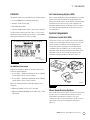
Asbestos and Non-Asbestos Fibers
i
WABCO Maintenance Manual MM-0112 (Revised 07-18)
ASBESTOS FIBERS WARNING
The following procedures for servicing brakes are recommended to reduce exposure to
asbestos fiber dust, a cancer and lung disease hazard. Material Safety Data Sheets are
available from WABCO.
Hazard Summary
Because some brake linings contain asbestos, workers who service brakes must understand the
potential hazards of asbestos and precautions for reducing risks. Exposure to airborne asbestos
dust can cause serious and possibly fatal disea
ses, including asbestosis (a chronic lung disease)
and cancer, principally lung cancer and mesothelioma (a cancer of the lining of the chest or
abdominal cavities). Some studies show that the risk of lung cancer among persons who smoke
and who are exposed to asbestos is much great
er than the risk for non-smokers. Symptoms of
these diseases may not become apparent for 15, 20 or more years after the first exposure to
asbestos.
Accordingly, workers must use caution to avoid creating and breathing dust when servicing brakes.
Specific recommended work practices for red
ucing exposure to asbestos dust follow. Consult your
employer for more details.
Recommended Work Practices
1. Separate Work Areas. Whenever feasible, service brakes in a separate area away from other
operations to reduce risks to unprotected persons. OSHA has set a maximum allowable level of
exposure for asbestos of 0.1 f/cc as an 8-hour time
-weighted average and 1.0 f/cc averaged over
a 30-minute period. Scientists disagree, however, to what extent adherence to the maximum
allowable exposure levels will eliminate the risk of disease that can result from inh
aling asbestos
dust. OSHA requires that the following sign be posted at the entrance to areas where exposures
exceed either of the maximum allowable levels:
DANGER: ASBESTOS
CANCER AND LUNG DISEASE HAZARD
AUTHORIZED PERSONNEL ONLY
RESPIRATORS AND PROTECTIVE CLOTHING
ARE REQUIRED IN THIS AREA.
2. Respiratory Protection. Wea
r a respirator equipped with a high-efficiency (HEPA) filter
approved by NIOSH or MSHA for use with asbestos at all times when servicing brakes, beginning
with the removal of the wheels.
3. Procedures for Servicing Brakes.
a. Enclose the brake assembly within a negative pr
essure enclosure. The enclosure should be
equipped with a HEPA vacuum and worker arm sleeves. With the enclosure in place, use the
HEPA vacuum to loosen and vacuum residue from the brake parts.
b. As an alternative procedure, use a catch
basin with water and a biodegradable,
non-phosphate, water-based detergent to wash the brake drum or rotor and other brake
parts. The solution should be applied with low pressure to prevent dust from becoming
airborne. Allow the solution to flow between the
brake drum and the brake support or the
brake rotor and caliper. The wheel hub and brake assembly components should be thoroughly
wetted to suppress dust before the brake shoes or brake pads are re
moved. Wipe the brake
parts clean with a cloth.
c. If an enclosed vacuum system or brake washing equipment is not available, employers may
adopt their own written procedures for servicing brakes, provided that the exposure levels
associated with the employer
’s procedures do not exceed the levels associated with the
enclosed vacuum system or brake washing equipment. Consult OSHA regulations for more
details.
d. Wear a respirator equipped with a HEPA filter approved by NIOSH or MSHA for use with
asbestos when grinding or machining b
rake linings. In addition, do such work in an area with
a local exhaust ventilation system equipped with a HEPA filter.
e. NEVER use compressed air by itself, dry brushing, or a vacuum not equipped with a HEPA
filter when cleaning brake parts or assemblies. NEVER use carcinogenic solvents, fla
mmable
solvents, or solvents that can damage brake components as wetting agents.
4. Cleaning Work Areas. Clean work areas with a vacuum equipped with a HEPA filter or by wet
wiping. NEVER use compressed air or dry sweeping to clean work areas. When you empty vacuum
cleaners an
d handle used rags, wear a respirator equipped with a HEPA filter approved by NIOSH
or MSHA for use with asbestos. When you replace a HEPA filter, wet the filter with a fine mist of
water and dispose of the used filter with care.
5. Worker Clean-Up. After servicing
brakes, wash your hands before you eat, drink or smoke.
Shower after work. Do not wear work clothes home. Use a vacuum equipped with a HEPA filter to
vacuum work clothes after they are worn. Launder them separately. Do not shake or use
compressed air to remove dust from work clothes.
6. W
aste Disposal. Dispose of discarded linings, used rags, cloths and HEPA filters with care,
such as in sealed plastic bags. Consult applicable EPA, state and local regulations on waste
disposal.
Regulatory Guidance
References to OSHA, NIOSH, MSHA, and EPA, which are regulatory agencies in the United States,
are made to provide further guidance to employers and workers employed within the United States.
Employers and workers employed outside of the United S
tates should consult the regulations that
apply to them for further guidance.
NON-ASBESTOS FIBERS WARNING
The following procedures for servicing brakes are recommended to reduce exposure to
non-asbestos fiber dust, a cancer and lung disease hazard. Material Safety Data Sheets
are available from WABCO.
Hazard Summary
Most recently manufactured brake linings do not contain asbestos fibers. These brake linings may
contain one or more of a variety of ingredients, including glass fibers, mineral wool, aramid fibers,
ceramic fibers and silica that can present health risks if inhaled.
Scientists disagree on the extent
of the risks from exposure to these substances. Nonetheless, exposure to silica dust can cause
silicosis, a non-cancerous lung disease. Silicosis gradually reduces lung capacity and efficiency
and can result in serious brea
thing difficulty. Some scientists believe other types of non-asbestos
fibers, when inhaled, can cause similar diseases of the lung. In addition, silica dust and ceramic
fiber dust are known to the State of California to cause lung cancer. U.S. and internation
al
agencies have also determined that dust from mineral wool, ceramic fibers and silica are potential
causes of cancer.
Accordingly, workers must use caution to avoid creating and breathing dust when servicing brakes.
Specific recommended
work practices for reducing exposure to non-asbestos dust follow. Consult
your employer for more details.
Recommended Work Practices
1. Separate Work Areas. Whenever feasible, service brakes in a separate area away from other
operations to reduce risks to unprotected persons.
2. Respiratory Protection. OSHA has set a maximum allowable level of exposure for silica of
0.1 mg/m3 as an 8-hour time-weighted average. Some manufacturers of non-asbestos brake
linings recommend that exposures to other ingredients found in non-asbestos brake linings be
kept below 1.0 f/cc as an 8-hour time-weighted average. Scientists dis
agree, however, to what
extent adherence to these maximum allowable exposure levels will eliminate the risk of disease
that can result from inhaling non-asbestos dust.
Therefore, wear respiratory protection at all times during brake servicing, beginning with the
removal of the wheels. Wear a respirator equipped with a high-efficiency (HEPA) filter approved by
NIOSH or MSHA, if the exposure levels may exceed OSHA or manufacturers’ recommended
maximum levels. Even when exposures are expected
to be within the maximum allowable levels,
wearing such a respirator at all times during brake servicing will help minimize exposure.
3. Procedures for Servicing Brakes.
a. Enclose the brake assembly within a negative pressure enclosure. The enclosure shoul
d be
equipped with a HEPA vacuum and worker arm sleeves. With the enclosure in place, use the
HEPA vacuum to loosen and vacuum residue from the brake parts.
b. As an alternative procedure, use a catch basin with water and a biodegradable,
non-phosphate, water-based detergent to wash the brake drum or rotor and other brake
parts. The solution should be applied with low pressure to prevent dust from becoming
airborne. Allow the solution to flow between the brake drum and the
brake support or the
brake rotor and caliper. The wheel hub and brake assembly components should be thoroughly
wetted to suppress dust before the brake shoes or brake pads are removed. Wipe the brake
p
arts clean with a cloth.
c. If an enclosed vacuum system or brake washing equipment is not available, carefully clean
the brake parts in the open air. Wet the parts with a solution applied with a pump-spray bottle
that creates a fine mist. Use a solution containing water, and, if available, a biodegradable,
non-phosphate, water-based detergent. The wheel hub and brake assembly components
should be thoroughly wetted to suppress dust before the brake shoes or brake pads a
re
removed. Wipe the brake parts clean with a cloth.
d. Wear a respirator equipped with a HEPA filter approved by NIOSH or MSHA when grinding or
machining brake linings. In addition, do such work in an area with a local exhaust ventilation
system equipped with a HEPA filter.
e. NEVER
use compressed air by itself, dry brushing, or a vacuum not equipped with a HEPA
filter when cleaning brake parts or assemblies. NEVER use carcinogenic solvents, flammable
solvents, or solvents that can damage brake components as wetting agents.
4. Cleaning Work Areas. Clean work areas with a vacuum equipped with a HEPA filter or by wet
wiping. NEVER use compressed air or dry sweeping to clean work areas. When you empty vacuum
cleaners and handle used rags, wear a respirator equipped with a HEPA filter approved by NIOSH
or MSHA, to minimize
exposure. When you replace a HEPA filter, wet the filter with a fine mist of
water and dispose of the used filter with care.
5. Worker Clean-Up. After servicing brakes, wash your hands before you eat, drink or smoke.
Shower after work. Do not wear work clothes home. Use a vacuum equipped with a HEPA filter to
vacuum work clothes after they are worn. Launder them separately. Do not shake or use
compressed air to remove dust from work clothes.
6. Waste Disposal. Dispose of discarded linings, used rags, cloths and HEPA filters with care,
such as in sealed plastic bags. C
onsult applicable EPA, state and local regulations on waste
disposal.
Regulatory Guidance
References to OSHA, NIOSH, MSHA, and EPA, which are regulatory agencies in the United States,
are made to provide further guidance to employers and workers employed within the United States.
Employers and workers employed outside of the United S
tates should consult the regulations that
apply to them for further guidance.

Contents
pg. pg.i Asbestos and Non-Asbestos Fibers
1 Section 1: Introduction
Contents
Anti-Lock Braking System (ABS)
System Components
Electronic Control Unit (ECU)
Wheel Speed Sensing Systems
2 Pressure Modulator Valves
3 Active Braking Valves (ABV)
Brake Pressure Sensor (BPS)
Steering Angle Sensor (SAS)
4 Electronic Stability Control (ESC) Module
Trailer Modulator Valve
Off-Road ABS Switch
ATC Switch
Blink Code Switch
System Configuration
6
Section 2: Stability and Safety Enhancement
Systems
ATC
ATC Components
ATC Switch
7 Roll Stability Control (RSC)
RSC Components
9 Electronic Stability Control (ESC)
ESC Components
11 Hill Start Aid (HSA)
HSA Components
12 Drag Torque Control
Lift Axle Capability
13
Section 3: Diagnostics, Troubleshooting and
Testing
General
Maintenance Information
ABS Indicator Lamp
14 Diagnostics
TOOLBOX™ Software Diagnostics
17 Blink Code Diagnostics (ABS Only)
23 Testing
Wheel Speed Sensor Testing
25 Modulator Valve Testing
29 Active Braking Valves (ABV) Testing
32 Brake Pressure Sensor Testing
33 ESC CAN Network Testing
ESC Module Testing
35 Steering Angle Sensor (SAS) Testing
37 ECU Circuit Testing
J1939 Serial Communications Testing
39
Section 4: Component Replacement
Component Removal and Installation
Wheel Speed Sensors
40 Modulator Valves
41 Active Braking Valves (ABV)
42 ABS Valve Packages
44 Active Braking Valve on the ABS Valve Package
45 Electronic Control Unit (ECU)
46 Steering Angle Sensor (SAS) — WABCO Only
47 Electronic Stability Control (ESC) Module
48 Brake Pressure Sensor
50
Section 5: System Configurations
System Configuration Layouts
52
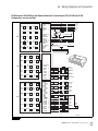
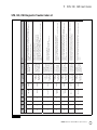
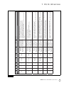
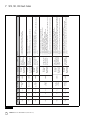
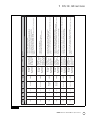
Section 6: Wiring Diagrams and Connectors
ECU Connector Pin Assignments
65
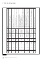
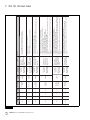
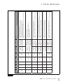
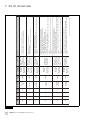
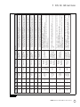
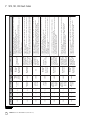
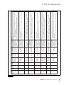
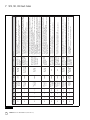
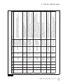
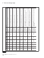
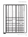
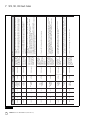
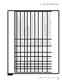
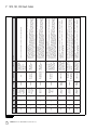
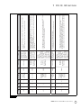
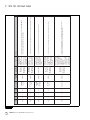
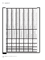
Section 7: SPN, SID, FMI Fault Codes
SPN, SID, FMI Diagnostic Trouble Code List
94
Section 8: Appendix I
Reconfiguration Procedure
How to Reconfigure an ECU (E Version)
TOOLBOX™ Software
95 Manual Reconfiguration
97
Section 9: Appendix II
E4 ESC End of Line Calibration Procedure
104
Section 10: Appendix III
E8 ESC End of Line Calibration Procedure
108
Section 11: Appendix IV
Aftermarket Programming
Aftermarket Programming Procedures
116 Aftermarket Programming Failure Codes List

1 Introduction
1
WABCO Maintenance Manual MM-0112 (Revised 07-18)
1 Introduction
Contents
This manual contains service information for the following systems.
앫 E version WABCO Anti-Lock Braking System (ABS)
앫 Automatic Traction Control (ATC)
앫 Roll Stability Control (RSC)
앫 Electronic Stability Controls (ESC) for trucks, tractors and buses
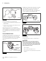
The ABS version is marked on the ECU. Figure 1.1. If you cannot
identify the ECU version installed on your vehicle, contact WABCO
North America Customer Care at 855-228-3203.
Figure 1.1
For Additional Information
Diagnostic and testing procedures for other ECU versions can be
found in the following manuals.
앫 C version ECUs — Maintenance Manual 28, Anti-Lock Braking
Systems (ABS) for Trucks, Tractors and Buses
앫 D version ECUs — Maintenance Manual 30, Anti-Lock Braking
Systems (ABS) for Trucks, Tractors and Buses
Refer to the following manuals for Trailer ABS diagnostics and
information.
앫 Maintenance Manual 33, Easy-Stop™ Trailer ABS
앫 Maintenance Manual MM-0180, Enhanced Easy-Stop™ Trailer
ABS with PLC
Anti-Lock Braking System (ABS)
ABS is a system designed to provide and maintain the best possible
traction and steering control during an extreme braking event.
During a potential wheel lock event, the ABS ECU, using information
provided by the wheel speed sensors, sends a signal(s) to the
appropriate modulator valve(s) to hold, apply or release the brakes
as needed. ABS works automatically, the driver does not have to
select this feature.
System Components
Electronic Control Unit (ECU)
The ECU is the control center or “brain” of the ABS, RSC and ESC
systems. It receives information from the sensors, processes data
and sends signals to modulators and active braking valves to
achieve different tasks. Depending on the system and vehicle
configuration, ECUs are available for cab- or frame-mounted
applications and are divided into Basic Cab, Universal Cab, Frame
and Advance Frame models. RSC and ESC systems are only
available on universal and advance frame ECUs. Figure 1.2.
Figure 1.2
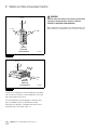
Wheel Speed Sensing Systems
Wheel speed sensing systems consist of a tooth wheel mounted on
the hub or rotor of each monitored wheel and a speed sensor
installed with its end against the tooth wheel. The sensor
continuously sends wheel speed information to the ECU. A sensor
clip holds the sensor in place and against the tooth wheel.
Figure 1.3.
Figure 1.1
4010603a
Figure 1.2
UNIVERSAL
ECU
FRAME-MOUNTED
ECU
BASIC
ECU
4003974a

1 Introduction
2
WABCO Maintenance Manual MM-0112 (Revised 07-18)
Figure 1.3
The type of axle determines sensor mounting location.
앫 Steering axle sensors are installed in the steering knuckle or in a
bolted-on bracket.
앫 Drive axle sensors are mounted in a block attached to the axle
housing or in a bolted-on bracket.
Check the wheel speed sensors for correct alignment and
adjustment. Apply lubricant to the sensor and sensor clip whenever
wheel-end maintenance is performed. Make sure tooth wheels are
free of contaminants. Refer to Section 3 and Section 4 for more
information.
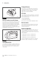
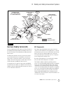
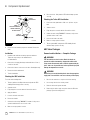
Pressure Modulator Valves
A modulator valve controls air pressure to an affected wheel-end
brake during an ABS, RSC or ESC event to reduce speed and
prevent wheel lock up. Modulator valves are also used during ATC
events to properly gain traction on the affected wheel end.
Figure 1.4.
Figure 1.4
A modulator valve is usually located on a frame rail or cross member
near the brake chamber or as part of a valve package. A valve
package combines two modulator valves, a service relay
(Figure 1.5) or quick release valve (Figure 1.6), and depending on
the vehicle configuration, an active braking valve (ABV).
Figure 1.5
Figure 1.6
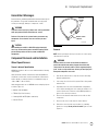
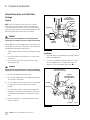
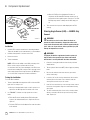
Easy Listening Tip!
To ensure the ABS valves are working — just listen! Figure 1.7.
WARNING
Park the vehicle on a level surface. Block the wheels to
prevent the vehicle from moving. Support the vehicle with
safety stands. Do not work under a vehicle supported only by
jacks. Jacks can slip or fall over. Serious personal injury and
damage to components can result.
1. Turn on the ignition.
2. Wait for the ABS indicator lamp to come on.
3. Listen for the valves to click or puff/chuff air in the order shown
in Figure 1.7.
Figure 1.3
Figure 1.4
1002009b
SENSOR
CLIP
SENSOR
TOOTH
WHEEL
BAYONET-STYLE
CONNECTOR
AIR IN
(PORT 1)
AIR OUT
(PORT 2)
4003992b
PRODUCT
IDENTIFICATION TAG
Figure 1.5
Figure 1.6
x
x
x
x
x
x
x
x
x
x
x
x
x
x
x
x
x
x
x
x
1002011a
472 500 30. 0
MADE IN GERMANY
001 20/98
1003359a

1 Introduction
3
WABCO Maintenance Manual MM-0112 (Revised 07-18)
Figure 1.7
NOTE: In previous versions of ABS, the valves are cycled
diagonally. Diagonal cycling does not occur with E version ABS.
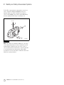
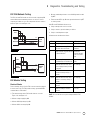
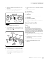
Active Braking Valves (ABV)
Active Braking Valves, sometimes referred to as ABVs or 3/2 valve,
are solenoid valves used for active braking during ATC, RSC or ESC
events. Depending on system configurations, ABVs can be located
in the front axle braking system, rear axle braking system and/or the
trailer service brake system. Figure 1.8.
Figure 1.8
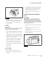
Brake Pressure Sensor (BPS)
The Brake Pressure Sensor or BPS is part of the RSC, ESC and HSA
system. It provides the system with the driver’s brake demand. The
sensor can be located in the primary or secondary delivery circuit
depending on the application. Figure 1.9.
Figure 1.9
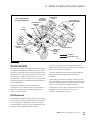
Steering Angle Sensor (SAS)
The Steering Angle Sensor (SAS) is part of the ESC system. The SAS
delivers the driver’s steering input (steering wheel position) to the
ECU using a dedicated ESC system internal data link. The ECU
supplies the sensor with voltage and ground. The SAS must be
calibrated using diagnostic tools whenever it is replaced, or when
any vehicle steering components are replaced or adjusted. Refer to
Section 8. Figure 1.10.
Figure 1.7
3 1
2 4
4 1
3 6
2 5
1002006d
4M CHANNEL
CAB
CURBSIDE
CAB
CURBSIDE
6M CHANNEL
Figure 1.8
Figure 1.9
4007846a
SOLENOID VALVE
(ACTIVE BRAKING VALVE)
CABLE
4006870a
27 FT-LB
(36.6 Nm)
TORQUE

1 Introduction
4
WABCO Maintenance Manual MM-0112 (Revised 07-18)
Figure 1.10
Electronic Stability Control (ESC) Module
The ESC module is part of the ESC system. It measures the vehicle
yaw rate as well as vehicle lateral acceleration. The ESC module
includes part of the ESC control algorithm. It exchanges data with
the ECU via the ESC system internal data link. The ECU supplies the
module with voltage and ground. The ESC module must be
initialized by diagnostic tools whenever the ECU or the ESC module
is replaced. Refer to Section 8. Figure 1.11.
Figure 1.11
Trailer Modulator Valve
In some stability control applications, an additional modulator valve
(the same as what is used for ABS modulation) will be located in the
trailer control line downstream of the 3/2 solenoid valve used to
control the trailer.
Off-Road ABS Switch
On some vehicles, an off-road ABS switch can be included. The
off-road ABS function improves vehicle control and helps reduce
stopping distances in off-road conditions or on poor traction
surfaces such as loose gravel, sand and dirt.
ATC Switch
A vehicle manufacturer might offer an ATC switch to control the ATC
function. Depending on the vehicle ECU configuration for the switch,
there are two function options.
앫 Deep snow and mud option
앫 ATC momentary override option
Refer to Section 2 for more information regarding these features.
Blink Code Switch
A vehicle manufacturer might offer a Blink Code switch to obtain
simple troubleshooting information. Refer to Section 3 for more
information about Blink Codes.
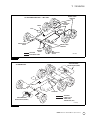
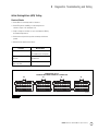
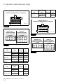
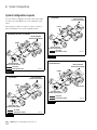
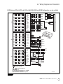
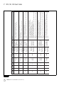
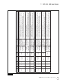
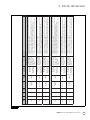
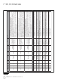
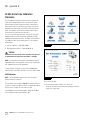
System Configuration
The system configuration is defined by the number of wheel end
sensors and modulator valves. There are three common system
configurations used with E version ECUs. Refer to Section 5 for more
system configurations.
앫 4S/4M (4 wheel speed sensors, 4 modulator valves)
앫 6S/4M (6 wheel speed sensors, 4 modulator valves)
앫 6S/6M (6 wheel speed sensors, 6 modulator valves)
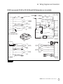
Each system configuration can have features such as ATC, HSA,
RSC or ESC. See Figure 1.12 and Figure 1.13 for an example.
Figure 1.10
Figure 1.11
4006873a
4010604a
WARNING
DO NOT MOVE OR RELOCATE

1 Introduction
5
WABCO Maintenance Manual MM-0112 (Revised 07-18)
Figure 1.12
Figure 1.13
Figure 1.12
1002004h
WHEEL SPEED
SENSORS
ABS
MODULATOR
VALVES
ABS
MODULATOR
VALVE
ABS
MODULATOR
VALVE
RELAY
VALVE
WHEEL SPEED
SENSORS
ECU
4S/4M CONFIGURATION — ABS ONLY
AIR LINES
ELECTRICAL LINES
LAMPS
QUICK
RELEASE
VALVE
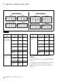
Figure 1.13
VALVE PACKAGE
INSTALLATION (REAR)
AIR LINES
LAMPS (UP TO
THREE: ABS,
TRAILER ABS, ATC)
LAMPS
4S/4M ABS/ATC
ATC VALVE
1002004g
VALVE PACKAGE
INSTALLATION (FRONT)

2 Stability and Safety Enhancement Systems
6
WABCO Maintenance Manual MM-0112 (Revised 07-18)
2 Stability and Safety Enhan ce ment Sy stem s
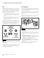
ATC
Automatic Traction Control is available as an option on all E version
ECUs and is standard on most. ATC helps improve traction in low
traction road conditions. ATC reduces the potential of jackknifing
caused by excessive wheel spin during acceleration or in curves.
ATC works automatically in two different ways.
A. When one drive wheel is spinning at a different speed than the
other, ATC momentarily applies the brake until traction is
regained.
B. When both drive wheels are spinning on a poor-traction
surface, ATC automatically reduces engine power to attain
optimum tire-to-road traction.
ATC will automatically turn on and off. Driver input is not required to
turn this feature on. If the vehicle experiences a traction control
event, the ATC indicator lamp will come on, indicating ATC is active.
The light turns off when the event has ended. Figure 2.1.
Figure 2.1
NOTE: Some vehicle manufacturers may refer to ATC as Anti-Spin
Regulation (ASR).
If ATC is installed, there will be an indicator lamp on the vehicle dash
or instrument panel marked ATC, ASR, or potentially Stability
Control, depending on the application.
ATC Components
ATC uses the base ABS components plus an active braking valve
that can be installed with individual modulator valves, or installed as
part of the rear valve package.
When installed with individual modulator valves, the active braking
valve is mounted on the frame or cross member, near the rear of the
vehicle.
When it is part of the rear valve package, the active braking valve is
attached to the relay valve. Figure 2.2.
Figure 2.2
ATC Switch
If the vehicle manufacturer offers an ATC switch to control the ATC
functionality, there are two common types of configuration settings
as follows.
앫 Deep snow and mud option: This function helps to increase
available traction on extra soft surfaces like snow, mud or gravel,
by slightly increasing the permissible wheel spin.
앫 ATC momentary override option: This function allows the
driver to momentarily disable/override ATC for the duration of the
ignition cycle.
When either option is in use, the ATC indicator lamp blinks
continuously to inform the driver. Figure 2.3.
Figure 2.1
NORMAL
VEHICLE
OPERATION
EXCESSIVE WHEEL
SPIN ATC
OPERATIONAL
(ATC LAMP COMES ON)
1002015a
(ATC LAMP IS OFF)
WHEELS
STOP
SPINNING
(ATC LAMP GOES OUT)
Figure 2.2
4010605a

2 Stability and Safety Enhancement Systems
7
WABCO Maintenance Manual MM-0112 (Revised 07-18)
Figure 2.3
Switch and lamp locations as well as ATC switch configuration will
vary depending on the vehicle make and model. Please check with
the vehicle manufacturer for correct information.
Here’s how the ATC switch works.
NOTE: Turning off the ignition will also deactivate either ATC
function.
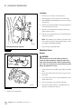
Roll Stability Control (RSC)
Roll stability control is an option designed to assist drivers in
managing the conditions that may result in vehicle rollovers. When
RSC senses conditions that may result in a rollover, it may reduce
engine torque, engage the engine retarder, apply pressure to the
drive axle brakes and may modulate the trailer brakes to slow the
vehicle down. Depending on the application and vehicle
configuration, the steer axle brakes may be applied as well.
Similar to ATC, RSC works automatically. The driver does not have to
select this feature. Unlike ATC, RSC cannot be turned off by the
driver.
RSC Components
RSC uses many of the same components used by ABS/ATC
including modulator valves, active braking valves and wheel speed
sensors. RSC ECUs are different from ABS ECUs as they contain an
internal accelerometer that measures and updates the lateral
acceleration of the vehicle and compares it to a critical threshold at
which rollover may occur.
Depending on the vehicle manufacturer, RSC ECUs have orientation
on the XX/YY or ZZ axis. For correct operation and the best
performance, verify the ECU is correctly leveled and securely
mounted. Figure 2.4, Figure 2.5 and Figure 2.6.
Figure 2.4
Figure 2.3
Driver Action
System
Response
Function
Active
Not
Active
Press ATC switch ATC lamp blinks
continuously
X
Press ATC switch
again
ATC lamp stops
blinking
X
1002018a
Figure 2.4
4010606a
Z ± 2°
X ± 2°
DRIVING
DIRECTION
+92°
-2°
Y
XX Orientation

2 Stability and Safety Enhancement Systems
8
WABCO Maintenance Manual MM-0112 (Revised 07-18)
Figure 2.5
Figure 2.6
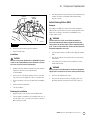
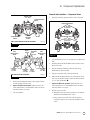
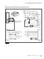
Certain vehicle configurations can have an additional active braking
valve for trailer service brakes, an active braking valve for front axle
brakes and a brake pressure sensor.
The active braking valve for trailer braking is a stand-alone valve
that is not available as part of the ABS/ATC valve package.
Depending on the application, a modulator valve may be located
downstream of the solenoid valve. Figure 2.7.
WARNING
RSC helps reduce the tendency of the vehicle to roll over when
cornering or changing directions, however, IT CAN NOT
PREVENT ALL ROLLOVERS FROM OCCURRING.
When operating the vehicle, always use safe driving techniques. The
driver is always the most important factor in safe vehicle operation.
Figure 2.5
Figure 2.6
4010607a
Z ± 2°
Y ± 2°
DRIVING
DIRECTION
+2° ± 90°
ZZ Orientation
4010608a
0° ± 2°
DRIVING
DIRECTION
0° ± 92°
X
Z
YY Orientation

2 Stability and Safety Enhancement Systems
9
WABCO Maintenance Manual MM-0112 (Revised 07-18)
Figure 2.7
Electronic Stability Control (ESC)
Electronic Stability Control (ESC) combines the rollover prevention of
Roll Stability Control (RSC) with directional stability in order to keep
the vehicle traveling on its intended path by providing spinout and
drift out control.
Like RSC, ESC is automatic. It becomes active when the system
senses imminent directional or roll instabilities, often before the
driver is aware. You will notice a difference in the vehicle when
stability control is functioning, but you should continue to drive as
normal and provide any additional needed corrections.
You may again notice a reduction in engine torque and additional
deceleration from the retarder, if so equipped. You also may notice
individual or all brakes applying depending on whether the vehicle is
in a roll or directional control event.
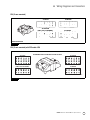
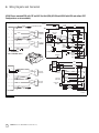
ESC Components
ESC is built from the ABS platform and uses many of the same
components as ATC and RSC. An active braking valve to control the
front axle brakes, a pressure sensor, an ESC module and a Steering
Angle Sensor (SAS) are required in addition to the components
necessary for RSC. Figure 2.8 and Figure 2.9. These components
are also described in the following section.
Note that for ESC applications on a non-towing vehicle (straight
truck), the trailer active braking valve is not required.
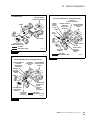
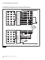
The ESC ECU is available in both Cab- and Frame-mounted
versions. The Universal Cab-Mounted ECU with ESC is an upgraded
version of the current Universal ABS ECU with a fourth connector
containing the necessary inputs/outputs required for full stability
control. The Frame-Mounted Advance ECU with ESC is an upgraded
version of the current ABS Frame-Mounted ECU with six additional
pins on both the X1 and X2 connectors of the ECU. These ECUs
support 4S4M, 6S4M and 6S6M vehicle configurations and are
compatible with 12V electrical systems. For pinout information, refer
to Section 6 of this manual.
Figure 2.7
4007813a
VALVE PACKAGE
INSTALLATION (REAR)
AIR LINES
ELECTRICAL LINES
4S/4M RSC/ATC
(ALSO AVAILABLE IN
6S CONFIGURATIONS)
VALVE PACKAGE
INSTALLATION (FRONT)
LAMPS
TRAILER STABILITY
CONTROL
MODULATOR
(OPTIONAL)
PRESSURE
SENSOR
(OPTIONAL)
ATC VALVE
FRONT AXLE
ACTIVE
BRAKING
VALVE
(OPTIONAL)
TRACTOR
PROTECTION
VALVE
TRAILER ACTIVE
BRAKING
VALVE

2 Stability and Safety Enhancement Systems
10
WABCO Maintenance Manual MM-0112 (Revised 07-18)
The ESC ECU contains parameter settings which are specific to a
vehicle configuration validated by WABCO Engineering. It is
imperative that the correct ECU is installed on your vehicle in
service. Contact WABCO or your respective vehicle OEM with any
questions regarding ESC ECU. Figure 2.8 and Figure 2.9.
Figure 2.8
NOTE: ESC modules are installed by the OEM close to the vehicle
center of gravity. Depending on the vehicle manufacturer, the ESC
module might face towards the front of the vehicle or rear. For
correct operation and the best performance, verify the ESC module
is correctly leveled and securely mounted according to OEM
specifications. Do not move the module to a different location as this
will affect the system performance.
Figure 2.8
4010609a
± 5°
-5°
Z
+2°
-2°
Y
+2°
-2°
X

2 Stability and Safety Enhancement Systems
11
WABCO Maintenance Manual MM-0112 (Revised 07-18)
Figure 2.9
Hill Start Aid (HSA)
Hill Start Aid (HSA) supports select automated manual transmissions
in reducing/totally eliminating the rolling back of the vehicle while
launching on a grade. When requested from the transmission, HSA
holds pressure in the service brakes of all axles of the towing vehicle
when the vehicle is standing still. HSA will hold pressure for a
maximum of three seconds following full release of the brake pedal.
Communication between the transmission and the ECU takes place
via the J1939 data link.
HSA grade threshold parameters may be modified in the
Transmission ECU. These parameters must be reviewed with the
transmission manufacturer prior to making any modifications in
order to ensure safe operation.
HSA Components
HSA is available on ABS ECUs with E4.4 software revision or higher.
Same as ESC, HSA is built from the ABS platform and uses many of
the same components as ATC and RSC. HSA uses the front axle
active braking valve as well as the rear active braking valve to help
maintain the pressure trapped during HSA activation.
A pressure sensor provides the system with the driver’s brake
demand. The measured pressure is used by HSA to set the trapped
pressure and/or activate the HSA function.
The vehicle manufacturer can provide an HSA switch multiplexed
through the dashboard or hard wired for momentary HSA
deactivation.
An HSA lamp, either hard wired or multiplexed, provides the driver
with a visual indication of system deactivation and/or active fault. If
the lamp is hard wired, it must be an incandescent lamp or LED with
a resistor to prevent the ECU from setting a fault code.
A failure detected on any of these components will lead to no HSA
availability. To troubleshoot the HSA, refer to Section 3 –
Diagnostics, Troubleshooting and Testing.
Figure 2.9
4007814a
VALVE PACKAGE
INSTALLATION (REAR)
AIR LINES
ELECTRICAL LINES
4S/4M ESC/ATC
(ALSO AVAILABLE IN
6S CONFIGURATIONS)
ESC
MODULE
LAMPS
TRAILER ACTIVE
BRAKING
VALVE
TRAILER STABILITY
CONTROL
MODULATOR
(OPTIONAL)
PRESSURE
SENSOR
ATC VALVE
SAS
FRONT AXLE
ACTIVE
BRAKING
VALVE
TRACTOR
PROTECTION
VALVE

2 Stability and Safety Enhancement Systems
12
WABCO Maintenance Manual MM-0112 (Revised 07-18)
Drag Torque Control
The ABS ECU has the ability to send a message to the engine to
increase engine RPM to prevent drive axle lock-up, if the vehicle is
on a downhill grade and in the incorrect gear.
Lift Axle Capability
Certain six sensor ABS ECUs with ATC allow third axle sensors to be
installed on a lift axle. These ECUs will not log a fault for the axle
being in the raised position while the vehicle is moving.

3 Diagnostics, Troubleshooting and Testing
13
WABCO Maintenance Manual MM-0112 (Revised 07-18)
3 Diagn ostics, Troublesho oting and Testin g
General
Maintenance Information
There is no regularly scheduled maintenance required for the
WABCO ABS, ATC, RSC or ESC systems. However, this does not
change current vehicle maintenance requirements.
앫 Lamp Check: To ensure the ABS tractor lamp is operating,
drivers should check the lamp every time the vehicle is started.
When the vehicle is started, the ABS lamp should come on
momentarily. If it does not come on, it could mean a burned-out
bulb.
앫 ABS Wheel Speed Sensors: Check the wheel speed sensor
adjustment and lubricate the sensor and sensor clip whenever
wheel-end maintenance is performed. Use only
WABCO-recommended lubricant, as specified in Section 4.
ABS Indicator Lamp
Two ABS indicator lamps, one for tractor and one for trailer, let
drivers know the status of the system. Figure 3.1. The tractor ABS
lamp is also used to display tractor blink code diagnostics. The
location of the ABS indicator lamps varies depending on the make
and model of the vehicle.
Figure 3.1
ATC and RSC/ESC functions may share the same dash indicator
lamp. Therefore, understanding how the ABS and ATC/RSC/ESC
lamps work is very important.
앫 If the vehicle is equipped with ATC, but not RSC/ESC, when the
ignition is turned to the ON position, the ABS and ATC lamps will
light for approximately three seconds, and then both lamps will
turn off simultaneously. Figure 3.2.
앫 If the vehicle is equipped with ATC and RSC/ESC, when the
ignition is turned to the ON position, the ABS and ATC/RSC/ESC
will both light but the ATC/RSC/ESC lamp will stay lit briefly after
the ABS lamp goes out.
Figure 3.2
The ABS indicator lamp works as follows:
NOTE: If the ECU senses a tractor ABS fault during normal vehicle
operation, the ABS indicator lamp will come on and stay on.
Figure 3.1
1002000a
Figure 3.2
ATC
ABS
Both lamps come
on at ignition ON
and turn off after
approximately three
seconds. Vehicle
equipped with
ABS and ATC.
ATC
ABS
Both lamps come
on at ignition ON.
ATC/RSC/ESC lamp
stays on briefly after
ABS lamp goes out.
Vehicle equipped
with ABS, ATC
and RSC/ESC.
4005299d
ATC
ABS
ABS
ATC

3 Diagnostics, Troubleshooting and Testing
14
WABCO Maintenance Manual MM-0112 (Revised 07-18)
Diagnostics
NOTE: Blink code diagnostics are not compatible with E8 software
versions.
Use any of the following methods to diagnose E version ECUs:
앫 Wabco TOOLBOX™ Software, a PC-based diagnostic and
testing program that runs in Microsoft Windows
XP, Vista,
Windows 7 or Windows 8 operating system.
앫 Blink Codes. Refer to the information in this section.
앫 OEM Diagnostic Displays. Refer to the vehicle operator’s manual.
If you have any questions about system diagnostics, please contact
WABCO North America Customer Care at 855-228-3203.
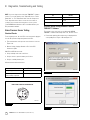
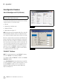
TOOLBOX™ Software Diagnostics
For complete instructions for installing and using TOOLBOX™
Software, refer to the User’s Manual posted on wabco-na.com.
WABCO TOOLBOX™ Software provides computer-based diagnostic
capabilities for the complete range of WABCO vehicle control
systems. The program provides the following functions:
앫 Displays both static (e.g., ECU number) and dynamic (e.g.,
RPMs) information from the system under test.
앫 Displays both active and stored system faults, as well as the
appropriate repair instructions.
앫 Activates system components to verify system integrity, correct
component operation and installation wiring.
NOTE: For E8 software versions, TOOLBOX™ 12 or higher is
required.
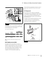
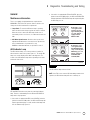
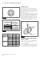
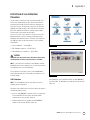
To display E version ABS, RSC, ESC or HSA faults:
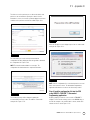
1. Connect the computer to the vehicle:
앫 Attach the USB/serial cable from your computer’s USB or
serial port to the adapter.
앫 Attach the Deutsch diagnostic cable from the adapter to the
vehicle. Figure 3.3.
Figure 3.3
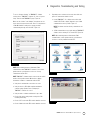
2. Select the TOOLBOX™ Software icon from the desktop or from
the Windows
Start Menu to display the Main Menu.
3. Adapter Selection
Verify the TOOLBOX™ Software is set for the device and
communication protocol that will be used.
To access “Adapter Selection” for TOOLBOX™ Software 11 or
newer, click on “Utilities” from the main TOOLBOX™ page or
under “System Setup” in “J1707/PLC TOOLBOX” from the
main TOOLBOX page. Figure 3.5.
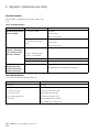
Ignition ON Normal Operation ABS lamp comes on at ignition
momentarily for a bulb check,
then goes out.
System is OK.
After servicing ABS
components
ABS lamp does not go out at
ignition.
When vehicle is driven at speeds
above 4 mph (6 km/h), lamp
goes out. System is OK.
Off-road ABS operation. Refer
to the off-road ABS information
in this section.
ABS lamp flashes during vehicle
operation.
The vehicle’s normal ABS
function is being modified due to
road conditions.
Existing fault or lamp issue ABS lamp does not go out at
ignition.
Lamp does not go out at speeds
above 4 mph (6 km/h) — a fault
may exist in the ABS system or
lamp is permanently shorted.
ON
OFF
1002005a
Figure 3.3
4010610a
TO VEHICLE
DEUTSCH
CONNECTOR
USB OR
SERIAL CABLE
ADAPTER

3 Diagnostics, Troubleshooting and Testing
15
WABCO Maintenance Manual MM-0112 (Revised 07-18)
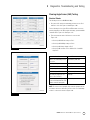
To access “Comport Settings” for TOOLBOX™ Software
versions prior to TOOLBOX™ Software 11, click on “System
Setup” from the main TOOLBOX™ page. Figure 3.6.
Make sure the “Vendor:” and “Adapter:” drop-downs are set
for the device being used and set the “Protocol:” drop-down to
J1708 OR J1939 according to the system you will be
communicating through, and click “OK”. Figure 3.4.
Figure 3.4
NOTE: When switching between J1939 and J1708
communications with TOOLBOX™ Software 11, the vehicle
ignition must be cycled between sessions to correctly
communicate with the ECU.
NOTE: TOOLBOX™ Software must be connected to the vehicle
and the vehicle ignition must be ON in order to display
information. If unable to communicate with the ECU:
앫 Verify device and data link connections are secure.
앫 Verify the device is RP1210A compliant and that the
comport settings (Vendor, Protocol, Adapter) in
TOOLBOX™ Software are correct.
앫 Verify the device software and firmware is up to date.
앫 Check all the powers and grounds coming to the ECU
including load testing.
앫 Check J1587 circuit at the ECU and the data link connector.
앫 Check J1939 circuit at the ECU and the data link connector.
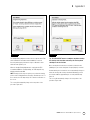
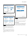
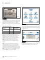
4. Depending on the software version used, there will be two
options to communicate with the vehicle:
앫 If using TOOLBOX™ 11 or higher and a vehicle with
Software ECU E4.4b or higher, diagnostics over J1939
communications can be possible. Figure 3.5.
NOTE: E8 software versions will only communicate over
J1939.
앫 J1708 communications are possible with any TOOLBOX™
Software version and any D or E Version ECU. Figure 3.6.
NOTE: When switching between J1939 and J1708
communications, vehicle ignition must be cycled between
sessions to correctly communicate with ECU.
Figure 3.5
Figure 3.6
Figure 3.4
4011997a
Figure 3.5
Figure 3.6
4010611a
WABCO TOOLBOX 11.5
WABCO TOOLBOX
4010612a
WABCO TOOLBOX J1 708 Diagnostics

3 Diagnostics, Troubleshooting and Testing
16
WABCO Maintenance Manual MM-0112 (Revised 07-18)
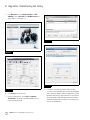
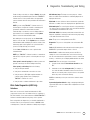
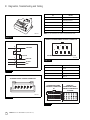
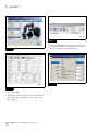
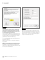
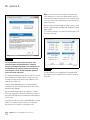
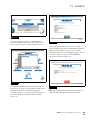
5. In the Main Menu, select J1939 Tractor ABS or J1708
TOOLBOX™, then Tractor ABS. The ABS Main Screen will
appear. Figure 3.7 and Figure 3.8.
Figure 3.7
Figure 3.8
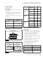
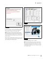
6. Select Display from the top menu.
7. From the pull-down menu, select Faults or Diagnostic
Trouble Codes. This will open the Fault Information screen.
Figure 3.9 and Figure 3.10.
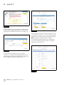
Figure 3.9
Figure 3.10
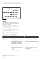
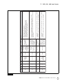
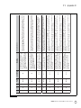
8. A description of the fault, the number of times the fault
occurred, the system identifier (SID), the failure mode (FMI) and
Suspect Parameter Number (SPN) are all displayed in the fault
information window. Basic repair instructions for each fault are
also provided. More detailed information about SID and FMI
troubleshooting and repair is provided in the following section
as well as the SID FMI table.
Figure 3.7
Figure 3.8
4010613a
WABCO Toolbox - Pneumatic ABS Diagnostics
WABCO Pneumatic ABS
4010614a
WABCO ABS
Figure 3.9
Figure 3.10
4010615a
4010616a
Page is loading ...
Page is loading ...
Page is loading ...
Page is loading ...
Page is loading ...
Page is loading ...
Page is loading ...
Page is loading ...
Page is loading ...
Page is loading ...
Page is loading ...
Page is loading ...
Page is loading ...
Page is loading ...
Page is loading ...
Page is loading ...
Page is loading ...
Page is loading ...
Page is loading ...
Page is loading ...
Page is loading ...
Page is loading ...
Page is loading ...
Page is loading ...
Page is loading ...
Page is loading ...
Page is loading ...
Page is loading ...
Page is loading ...
Page is loading ...
Page is loading ...
Page is loading ...
Page is loading ...
Page is loading ...
Page is loading ...
Page is loading ...
Page is loading ...
Page is loading ...
Page is loading ...
Page is loading ...
Page is loading ...
Page is loading ...
Page is loading ...
Page is loading ...
Page is loading ...
Page is loading ...
Page is loading ...
Page is loading ...
Page is loading ...
Page is loading ...
Page is loading ...
Page is loading ...
Page is loading ...
Page is loading ...
Page is loading ...
Page is loading ...
Page is loading ...
Page is loading ...
Page is loading ...
Page is loading ...
Page is loading ...
Page is loading ...
Page is loading ...
Page is loading ...
Page is loading ...
Page is loading ...
Page is loading ...
Page is loading ...
Page is loading ...
Page is loading ...
Page is loading ...
Page is loading ...
Page is loading ...
Page is loading ...
Page is loading ...
Page is loading ...
Page is loading ...
Page is loading ...
Page is loading ...
Page is loading ...
Page is loading ...
Page is loading ...
Page is loading ...
Page is loading ...
Page is loading ...
Page is loading ...
Page is loading ...
Page is loading ...
Page is loading ...
Page is loading ...
Page is loading ...
Page is loading ...
Page is loading ...
Page is loading ...
Page is loading ...
Page is loading ...
Page is loading ...
Page is loading ...
Page is loading ...
Page is loading ...
Page is loading ...
Page is loading ...
-
 1
1
-
 2
2
-
 3
3
-
 4
4
-
 5
5
-
 6
6
-
 7
7
-
 8
8
-
 9
9
-
 10
10
-
 11
11
-
 12
12
-
 13
13
-
 14
14
-
 15
15
-
 16
16
-
 17
17
-
 18
18
-
 19
19
-
 20
20
-
 21
21
-
 22
22
-
 23
23
-
 24
24
-
 25
25
-
 26
26
-
 27
27
-
 28
28
-
 29
29
-
 30
30
-
 31
31
-
 32
32
-
 33
33
-
 34
34
-
 35
35
-
 36
36
-
 37
37
-
 38
38
-
 39
39
-
 40
40
-
 41
41
-
 42
42
-
 43
43
-
 44
44
-
 45
45
-
 46
46
-
 47
47
-
 48
48
-
 49
49
-
 50
50
-
 51
51
-
 52
52
-
 53
53
-
 54
54
-
 55
55
-
 56
56
-
 57
57
-
 58
58
-
 59
59
-
 60
60
-
 61
61
-
 62
62
-
 63
63
-
 64
64
-
 65
65
-
 66
66
-
 67
67
-
 68
68
-
 69
69
-
 70
70
-
 71
71
-
 72
72
-
 73
73
-
 74
74
-
 75
75
-
 76
76
-
 77
77
-
 78
78
-
 79
79
-
 80
80
-
 81
81
-
 82
82
-
 83
83
-
 84
84
-
 85
85
-
 86
86
-
 87
87
-
 88
88
-
 89
89
-
 90
90
-
 91
91
-
 92
92
-
 93
93
-
 94
94
-
 95
95
-
 96
96
-
 97
97
-
 98
98
-
 99
99
-
 100
100
-
 101
101
-
 102
102
-
 103
103
-
 104
104
-
 105
105
-
 106
106
-
 107
107
-
 108
108
-
 109
109
-
 110
110
-
 111
111
-
 112
112
-
 113
113
-
 114
114
-
 115
115
-
 116
116
-
 117
117
-
 118
118
-
 119
119
-
 120
120
-
 121
121
-
 122
122


WABCO ABS Maintenance Manual
- Type
- Maintenance Manual
Ask a question and I''ll find the answer in the document
Finding information in a document is now easier with AI
Related papers
Other documents
-
Excel TB140- Black Operating instructions
-
-
BENDIX BW2266 User manual
-
-
-
 Detroit Diesel EPA07 Series 60 DDEC VI Troubleshooting Manual
-
Intronics HDMI-A M/M 3.0m User manual
-
-
 John Deere Products & Services AC-6000SB User manual
-

