Page is loading ...

Apr 30 2009 Copyright RED Digital Cinema
1
RED ONE™ CAMERA: OPERATIONS GUIDE
(Firmware Build 17, Version 3.4.1)
Sections: Page
1. Before You Start 3
2. Camera Assembly 6
3. Physical Controls 8
4. Theory of Operation 12
5. Basic Operation 19
6. Sensor Menu Controls 26
7. Audio Video Menu Controls 34
8. System Menu Controls 42
Appendix A. Upgrading camera firmware 63
Appendix B. Digital Media Management 65
Appendix C: Input and Output Connectors 69
Appendix D: Post Production 79

Copyright RED Digital Cinema Apr 30 2009
2
---------------------------------
DISCLAIMER
RED has made every effort to provide clear and accurate information in this Operations Guide,
which is provided solely for the user’s information. While thought to be accurate, the informa-
tion in this document is provided strictly “as is” and RED will not be held responsible for issues
arising from typographical errors or user’s interpretation of the language used herein that is dif-
ferent from that intended by RED. All safety and general information is subject to change as a
result of changes in local, federal or other applicable laws.
RED reserves the right to revise this Operations Guide and make changes from time to time in
the content hereof without obligation to notify any person of such revisions or changes. In no
event shall RED, its employees or authorized agents be liable to you for any damages or
losses, direct or indirect, arising from the use of any technical or operational information con-
tained in this document.
----------------------------------

Apr 30 2009 Copyright RED Digital Cinema
3
1. Before you start.
Congratulations on your purchase of a RED ONE™ camera. Please read the attached safety
instructions, then carefully unpack the camera body any accessories. If there is any physical
damage to your camera or accessories, please file a support ticket at www.red.com/support.
RED ONE™ ™ Digital Cinema
IMPORTANT INFORMATION—READ BEFORE USING YOUR CAMERA
GENERAL USE.
DO NOT MODIFY OR DISMANTLE: Do not attempt to open your camera, lens or other acces-
sory as doing so may expose you to electric shock and serious injury. There are no user-
serviceable parts inside. Alteration or repairs made to the camera, lens or other accessory, ex-
cept by a RED authorized service facility, will void the Limited Warranty. Users are not permit-
ted to make design changes or otherwise modify the operation of the camera, lenses or other
accessories, without the express written approval of RED Digital Cinema.
STORAGE: Store in a protected, level and ventilated place. Avoid exposure to temperature ex-
tremes, damp, severe vibration, strong magnetic fields, direct sunlight or local heat sources
during storage. Remove any batteries from the camera before storage.

Copyright RED Digital Cinema Apr 30 2009
4
Note that storing batteries fully charged or in high temperature conditions may permanently
reduce the life of the battery. Available battery capacity may also be temporarily lessened after
storage in low temperature conditions.
The recommended storage and usage temperatures for your camera, lenses and other acces-
sories are:
Operating range: 0C to +40C (32F to 104F)
Storage range: -20C to +50C (-4F to 122F)
If there are any performance issues with your camera or accessories within this operating
range, please file a support ticket on www.red.com/support.
MOISTURE: Avoid exposing your camera to moisture. The unit is not waterproof, so contact
with water could cause permanent damage to the unit as well as electric shock and serious
injury to the user. Do not use the camera in the rain or under other conditions with high mois-
ture and immediately remove the power source if exposed to moisture.
AVOID SHOCK: Do not expose your camera to excessive vibration or impact. Be careful not to
drop your camera. Internal mechanisms may be damaged by severe shock. Mechanical align-
ment of optical elements may be affected by excessive vibration.
CLEANING: When cleaning your camera, remember that it is not waterproof and moisture can
damage electronic circuitry. Do not rinse or immerse any element of the camera, lens or other
accessory, keep them dry at all times. Do not use soaps, detergents, ammonia, alkaline clean-
ers, and abrasive cleaning compounds or solvents. These substances may damage lens coat-
ings and electronic circuitry.
LASER BEAMS.
Avoid imaging of laser beams as they may cause damage to the sensor.
BATTERY.
Lithium Ion batteries may be subject to special handling requirements pursuant to federal and
local laws. Please refer to specific shipping instructions included with your battery regarding
proper transport of your battery. Do not handle your battery if it is damaged or leaking. Dis-
posal of batteries must be in accordance with local environmental regulations. For example,
California law requires that all rechargeable batteries must be recycled by an authorized recy-
cle center.
ELECTROMAGNETIC INTERFERENCE.
The use of devices using radio or other communication waves may result in the malfunction or
interference with the unit and/or with audio and video signals.

Apr 30 2009 Copyright RED Digital Cinema
5
FCC RULES.
This equipment has been tested and found to comply with the limits for a Class A digital device
pursuant to Part 15 of the FCC Rules. These limits are designed to proved reasonable protec-
tion against harmful interference when the equipment is operated in a commercial environ-
ment.
This equipment generates, uses, and can radiate radio frequency energy and, if not installed
and used in accordance with the instructions, may cause harmful interference to radio com-
munications. Operation of this equipment in a residential area is likely to cause interference, in
which case, the user will be responsible for correcting the interference at the user’s own ex-
pense.

Copyright RED Digital Cinema Apr 30 2009
6
2. Camera Assembly
Connect the power cable from the Battery Plate, RED-CHARGER or AC Power Adaptor to the
DC input on the rear of the camera body.
The RED-LCD and RED--EVF viewfinder may be mounted to the camera body using a short or
extended length RED ARM. Attach the RED ARM to the camera body using the shorter threaded
screw. There are attachment points on the camera body and on the RED RAIL TOP BRACKET.
Then attach the end of the arm with the circular locking ring to the RED-LCD or RED-EVF.
Finally connect the cable from the camera body to the RED-LCD or RED-EVF. Carefully align the
red dots on the socket and plug, and push firmly to establish contact.
Attaching the RED-LCD or RED-EVF
The RED-LCD and RED-EVF cables are interchangeable; but the outputs are not. The RED-EVF
should be connected to the upper output; a RED-LCD should be connected to the lower output.
If using RED-DRIVE, place it into the RED-CRADLE and secure it with the four thumbscrews.
Then connect the RED e-SATA cable to the RED-DRIVE™ and to the e-SATA input on the rear of
the camera body. (In normal operation use the right angle connector to mate to the RED-DRIVE,
and the straight connector to mate to the camera)
Remove the lens cap and mount the PL lens you wish to use. The lens will have four metal tabs
with cutouts for the registration pin in the mount. If using S4/i compatible lenses the data pins
should be oriented to 12 o’clock when mounting the lens in order to establish communication.
Attach matte box and motors, and any auxiliary power cables required to power these items.

Apr 30 2009 Copyright RED Digital Cinema
7
Insert the digital media, such as RED-FLASH 8GB or 16GB compact flash (CF) card, or connect
a RED-DRIVE™ hard disk drive, or RED-RAM™ flash drive via the RED custom e-SATA cable.
Inserting a Compact Flash card
Attach a RED-BRICK 140 battery using the v-mount battery plate, or connect an AC Power
Adaptor or a RED-CHARGER to the DC input on the rear of the camera body. Now adjust the
balance of the camera. The RED CRADLE/Universal Rail mount unit slides on 19mm rods so you
can adjust the distance to the camera back. Find the position that best offsets the weight of the
lens.
Finally tighten the butterfly locks to maintain that position. The shoulder pad/wedge plate adap-
tor is also designed to slide within the RED RAIL base plate until you lock it in place. You won’t
need to remove it to mount the camera on a tripod.
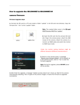
Power up.
Press the On/Off switch to power the camera. The rear status display will illuminate, and after
approximately 60 seconds it will display the camera PIN, firmware build and firmware version.
The P.I.N is a unique product identification number in the format ABC_123_XYZ. This code is in-
cluded in the metadata recorded with each image. The PIN provides RED with tracking data for
customer service and assistance in authenticating legal ownership of the camera.
When the camera is ready for use, the lower LED to the right of the status display turns green.

Copyright RED Digital Cinema Apr 30 2009
8
3. Physical Controls and Connectors
This section describes the physical controls and connectors on the RED ONE™ camera body.
A. PL Lens Mount B. Record C. User Keys 1 and 2
A PL mount is provided as standard with the RED ONE™ camera. The mount is compatible
with the majority of S35mm, 35mm and S16mm cinematography lenses. In addition, broadcast
B4 mount lenses may be used if the camera is equipped with the optional B4 to PL mount op-
tical converter.
The PL mount includes a 4-pin S4/i data interface. This allows the camera to gather lens meta-
data from lenses supplied by RED and Cooke Optics. Ltd, using the S4/i protocol.
On the left side of the camera body are a RECORD key and two User Keys. User Key 1 is pre-
assigned to AUTO WB and User Key 2 is pre-assigned to 1:1 FOCUS CHECK, however these
assignments can be changed in the KEYMAP preferences menu.
A SD Memory Card slot is located below this group of keys, which supports most SD Cards of
up to 1GB capacity. It is not possible to store video or audio data to the card SD card, however it
may be used for camera firmware upgrades and to store USER PROFILE and LOOK files.

Apr 30 2009 Copyright RED Digital Cinema
9
A Headphone B Program HD-SDI (A) C Program HD-SDI (B)
D HDMI Out E Preview HD-SDI F Video Genlock
G USB-2 (peripheral) H USB-2 (computer) I Audio Monitor
J Timecode K Audio Ch 1 – 4 (1-2 Upper Left - Right, 3-4 Lower Left - Right)
L RED-EVF M RED-LCD N Aux / RS232
The right side of the camera contains all the video, audio and time code inputs and outputs.
From top left to bottom right, these comprise a 3.5mm stereo headphone jack, and four DIN
1.0/2.3 video connectors that support Program HD-SDI, Preview HD-SDI and Video Genlock.
Next is an HDMI output, a USB-2 “master” port for USB peripheral devices, a USB-2 “slave”
port to connect the camera to another camera or computer based controller, a 5-pin mini-XLR
audio output, a 5-pin timecode input/output and four three-pin mini-XLR audio inputs. Finally
there are two 16-pin push lock LEMO connectors that provide video, communications and
power for a RED-EVF and RED-LCD, and a 10-pin push lock LEMO connector supporting the
Aux/RS232 port that can interface to a variety of B4 lenses and lens motor control devices.
One 6-inch length DIN 1.0 / 2.3 to BNC video adaptor cable and one 9-inch length 3 pin mini-
XLR to mini-XLR cable plus a mini-XLR to full size XLR adaptor are provided with the camera.
Additional video and audio adaptor cables may be ordered online at www.red.com/store
Note: Cameras shipped prior to Sept 15th 2008, may have an earlier revision of the audio
board and no S4/i pins installed in the P/L mount. Contact RED customer service about
appropriate audio cables to use with these systems, and hardware upgrade options.

Copyright RED Digital Cinema Apr 30 2009
10
A User Menus select B Status Display C Record & Ready tallies
D Sensor menu E EXIT menu F UNDO / alternate action
G Record Start / Stop H Joystick I Audio / Video menu
J System menu
On the rear of the camera, several buttons surround a daylight readable LCD status display.
To the left of the status display are three User Menu buttons, which normally provide direct ac-
cess Sensitivity, Shutter and Color Temperature menus. However the specific function of these
keys may be re-programmed by the user, if desired, to provide quick access to other functions.
Below the LCD status display are the Joystick, and Exit, Undo / alternate action and RECORD
buttons, plus the Sensor, Audio / Video and System menu buttons. The camera control menus
are logically grouped under these last three buttons to provide streamlined camera operations.
The status display reports key camera status values, and is complimented by two LED’s: the red
LED provides a record tally, while the green LED indicates the camera is ready for operation.
The five buttons above the LCD display control clip playback. From left to right, the keys are Clip
Start / Previous Clip, Play Reverse, Clip Play / Pause, Fast Fwd and Clip End / Next Clip.

Apr 30 2009 Copyright RED Digital Cinema
11
A Power On/Off switch B Aux Power / GPIO A
C Aux Power / GPIO B D Camera 11.5 - 17V D.C Input
E e-SATA Interface (to RED-DRIVE™ or RED-RAM™ digital magazine)
Underneath the status display key group are the Power On/Off switch (top left) two 4 pin Auxiliary
Power / GPIO outputs, 6 pin camera system POWER input and a 16 pin DRIVE interface.
Each Auxiliary Power / GPIO connector can supply 1.75 amps of unregulated 11.5 – 17V DC to
accessories such as range finders or low power lens motors. The upper connector provides a
GPI trigger (user programmable but defaulted to Record Start / Stop) and a Record Tally output.
The lower connector provides a GPI trigger (user programmable but defaulted to Single Frame
Record) and a Frame Recorded Tally output.
The DRIVE interface supplies power and data over e-SATA protocols to record REDCODE™
(TM) RAW compressed video data, metadata and audio to RED-DRIVE™ or RED-RAM™ digital
media.
Power Up.
To power the camera up from a RED BRICK battery, press the power on/off switch once.
To power the camera up from a RED-CHARGER, connect it via the supplied power cable. Plug
the RED-CHARGER into an AC power source and switch it on. After the green LED illuminates on
the RED-CHARGER, the camera can be powered on by pressing its On/Off switch.
To power the camera down, press the power on/off switch once.
Note: After power down, is recommended that you wait approximately 10 seconds after
the camera’s green status LED goes off before powering the camera up again. If the green
LED on the charger lights but then goes out, press the camera power On/ Off switch twice.

Copyright RED Digital Cinema Apr 30 2009
12
4. Theory of Operation
The RED ONE™ ™ Digital Cinema camera provides high performance digital imaging over a
wide range of frame rates and optical formats including Super 35mm, 35mm and Super16mm.
The camera is supplied as standard with a PL mount, and may be configured with 19 mm rods
to accommodate most cinematography lenses, matte boxes and follow focus systems. Adap-
tors for 15mm offset studio and 15mm lightweight rods are also available.
In addition to compatibility with existing PL mount cinematography lenses; a select range of
S35/35mm format PL mount prime and zoom lenses are available from RED Digital Cinema.
Other lens mounts, including Canon FD, and Nikon F are available from RED and 3
rd
parties,
permitting the use of Nikkor and Canon photographic lenses. To use these mounts the PL
mount must be removed. It is recommended that this should be done only in a dust-free envi-
ronment, as the sensor and optical path will be exposed to the elements during this process.
A B4 mount to PL mount adaptor is also available to permit use of 2/3” HD lenses on the RED
ONE™ camera. The optical coverage it provides is equivalent to S16 mm. Hence, the maximum
recording resolution with these lenses will be 2K RAW. (2048 x 1152 pixel progressive scan)
MYSTERIUM™ Sensor
The MYSTERIUM™ sensor has been specifically designed for use with the RED ONE™ cam-
era, and provides variable frame rate imaging over 1- 60fps in 4K or 3K resolution, and 1-
120fps in 2K resolution record modes.
Native color balance for the MYSTERIUM™ sensor is 5,000 degrees Kelvin, but may be elec-
tronically compensated for any color temperature in the range 1,700 to 10,000 Kelvin. White
Balance presets are available for Tungsten (3200K) and Daylight (5600K) lighting; the camera
may also calculate a color neutralizing White Balance value using a standard white card tech-
nique.
MYSTERIUM™ includes integrated 12-bit resolution analog to digital conversion, capable of
delivering up to 11 stops of dynamic range when operating in daylight at a sensitivity of 320
ISO.
Image Processing
Images received from the MYSTERIUM™ sensor are formatted as pixel defect corrected (but
not color processed) 12-bit RAW data - similar in image quality to a high end digital stills cam-
era.
The sequence of 12-bit RAW images received from the sensor is compressed using proprietary
wavelet based REDCODE™ RAW compression. The RAW data recorded is independent of the
RGB signal monitored from the monitoring path. ISO, white balance or other RGB color space
adjustments made to the monitoring path are not burned into the recorded 12-bit RAW data.

Apr 30 2009 Copyright RED Digital Cinema
13
Images can be stored on a high-speed Compact Flash, RED-DRIVE™ or RED-RAM™ media.
The camera’s monitoring path converts 12-bit RAW sensor data white balanced 10-bit 1280 x
720 pixel RGB 4:4:4 video. This signal may be modified using ISO, white balance or other RGB
color space adjustments and provides monitor feeds for the RED-EVF, RED-LCD, Preview HD-
SDI and HDMI outputs.
Audio Recording
The RED ONE™ includes four channels of analog audio input processing, Peak Level meter,
headphone monitor and 2-channel balanced analog audio output. Audio is digitized at 24-bit
depth and 48KHz and recorded in synchronization with video and timecode to the attached
media. Digital audio is also embedded in the HDMI, Preview and Program HD-SDI outputs.
Line Level and Microphone Level analog audio input signals are routed via a high quality A/D and
pre-amplifier, whose gain stage may be controlled using the Input Level control to achieve the
desired audio reference / recording level.
Line Level Inputs
Line level audio inputs are designed to operate at unity gain (0dB Input Level), therefore an ap-
propriate line output level should be established by your field production mixer or other external
signal source.
Reference signal level for Line inputs is 0dBu / 0.775 volts RMS / -20dBFS when operating at
0dB Input Level. The maximum input signal that can be applied before the onset of input signal
clipping is +18dBu / 6.5 volts RMS / - 2dBFS. i.e. this setting supports a guaranteed minimum of
18dB of input signal headroom above reference, plus the maximum available Signal to Noise Ra-
tio for the resulting 24-bit digital recording.
Microphone Level Inputs
The recorded signal levels of Microphone inputs are affected by the sensitivity of the microphone
and the Input Level setting. Range is +10dB to +54dB, with a default value of +32dB. The cam-
era operator should choose an Input Level that aligns the input signal to the reference line drawn
vertically through the camera’s PPM, indicating 0dBu.
This setting supports a guaranteed minimum of 18dB of input signal headroom above reference,
plus the maximum available Signal to Noise Ratio for the resulting 24-bit digital recording.
Video Monitoring Outputs
In its default configuration, the RED ONE™ camera can simultaneously support a RED-EVF,
RED-LCD, 3 HD-SDI outputs and one HDMI output, with two of these outputs supporting full
GUI overlay graphics.
Default setting for GUI support is RED-EVF and RED-LCD. However, if either one of these is

Copyright RED Digital Cinema Apr 30 2009
14
not present, full GUI overlay support is automatically enabled on HD-SDI and HDMI outputs.
RED-EVF: 1280 x 848 resolution RGB 4:4:4 progressive video display with Surround View,
frame guides and safe action / title overlays, zebra and false color exposure overlays, wave-
forms, camera status and operation menus.
RED-LCD: 1024 x 600 resolution RGB 4:4:4 progressive video display with Surround View,
frame guides and safe action / title overlays, zebra and false color exposure overlays, wave-
forms, camera status and operation menus.
PROGRAM HD-SDI: When in record mode, these connectors provide two extra copies of the
HD-SDI PREVIEW signal. When in playback mode, these connectors provide a dual-link 10-bit
RGB 4:4:4 video signal.
PREVIEW HD-SDI: 1280 x 720 resolution 10-bit 4:2:2 video output (720p 50.00 /59.94 Hz).
PREVIEW HDMI: 1280 x 720 resolution 10-bit 4:2:2 video output (720p 50.00 /59.94 Hz).
Note: If a RED-EVF or RED-LCD is connected, the PREVIEW HD-SDI and HDMI outputs
will provide Surround View, frame guides, safe action / title, and timecode / clip name. If
both RED-EVF and RED-LCD are connected, these outputs only support Surround View.
Note: Only if a RED-EVF or RED-LCD is connected, the HDMI output can also support a
1280 x 848 resolution video output with Surround View, frame guides, safe action / title,
timecode / clip name, waveform, and camera status and operation menu overlays. This
signal should be compatible with the majority of DVI based SXGA+ computer monitors.
To select between these modes, press the SYSTEM menu key, and then MONITOR.
Press the joystick in, and then push the joystick to the right to highlight PREVIEW.
Rotate the joystick to select VIDEO (720p) or MENUS (DVI). The default is VIDEO (720p)
Press the EXIT key to return to the main camera menu. The Preview Output setting will be held
in camera memory. Once it is set it will not need to be re-set when power cycling the camera.
RED-LCD and RED-EVF
The optional RED-LCD and RED-EVF are specialized video monitors, that may be attached to
the camera body, and provide a variety of user tools to assist framing, focus and exposure.

Apr 30 2009 Copyright RED Digital Cinema
15
- Surround View, which is an additional visible area outside the actual recorded image.
- Frame guidelines show common film presentation and television formats such as 2.40:1
and 1.85:1, picture center, and/or television aspect ratios such as 16:9, 14:9 and 4:3.
- Focus is aided by the high resolution of the displays, 1:1 Focus Check function, and two
user selectable waveform based focus assist meters.
- Exposure is aided by dual zebras a false color meter and Luma and RGB histograms.
System information including instantaneous frame rate, sensitivity, shutter speed, color tem-
perature, recording format, clip name, timecode, battery and media remaining is provided in
the RED-LCD or RED-EVF monitor outputs, and the rear status display on the camera back.
For applications where a RED-LCD or RED-EVF are not desired – for example working on a
crane – the Surround View video, frame guides, and exposure overlays are also available on
the Preview HD-SDI output, providing remote camera monitoring up to 200 ft away.
Digital Magazines
REDCODE™ RAW compressed video, time code, audio and metadata, may be recorded to on-
board or attached digital media devices including -

Copyright RED Digital Cinema Apr 30 2009
16
RED-FLASH: RED record speed verified 8GB or 16GB Compact Flash cards.
RED-DRIVE: A hard disk media based Digital Magazine of 320GB capacity.
RED-RAM™: A solid-state flash media based Digital Magazine of 128GB capacity.
Note: Digital Magazines may be directly connected to a computer via FireWire or USB-2.
Each clip is recorded with a unique clip name and with all the appropriate elements of the clip –
REDCODE™ RAW files and QuickTime Reference files placed in a clip folder (.RDC)
All clips are in turn placed in a root directory (.RDM) The root directory (folder) contains all the
clips recorded on that specific piece of digital media, so copying of clips from the digital maga-
zine to backup media may be performed by a single drag and drop operation.
Record Indication
On record, the RED ONE™ camera provides a variety of record tallies. Timecode, normally
displayed in white colored text, will turn red, and a small red dot will appear in the top left cor-
ner of the video monitoring outputs. The upper LED to the right of the status display screen will
turn red, and if using an EVF, the front LED will also turn red. If media is not present, the cam-
era will provide a warning as follows – RECORD ERROR NO_DIGIMAG.
Metadata
RED ONE™ cameras record Metadata, which is data that describes the precise characteristics
of the picture and sound data, in each frame of footage. This may include camera specific
setup information, project and clip management information, Edge code, Time code, date and
GMT, lens parameters, audio settings and any video image processing information.
Clip Naming Conventions
When you push record, the camera names the clip being recorded on the digital media. The
format of the clip name is Camera Letter + Reel Number + Month + Day + ** where ** is a two
digit alphanumeric random number generated by the camera for each file

Apr 30 2009 Copyright RED Digital Cinema
17
E.g. A001_C002_0502A6.RDC
Where: A = camera A, 001 = reel 001, C002 = clip 002, and 0502 = May 02
And A6 is a two digit alphanumeric random number generated by the camera. This number
helps avoid duplicate file names if two cameras are inadvertently named A on the same set.
Three cameras identified as A, B and C can therefore have individually recognizable clips
A001_C001_0502**.RDC B001_C001_0502**.RDC C001_C001_0502**.RDC
A single camera identified as A can have individually recognizable reel numbers, such as
A001_C001_0502**.RDC, A002_C001_0502**.RDC, and A003_C001_0502**.RDC
A single camera identified as A can have individually recognizable clip numbers, such as
A001_C001_0502**.RDC, A002_C002_0502**.RDC, and A003_C003_0502**.RDC
Note - Even if the same Reel number and / or camera name are reused, the use of the two
character random files generated non-duplicate file names, such as
A001_C001_0502A6.RDC, A001_C001_050267.RDC, and A001_C001_0502F8.RDC
Under normal operation, the reel number increments each time the camera formats a new
piece of digital media, up to a maximum value of 999. However the reel number may be manu-
ally reset at any time to 001or other desired value.
A001_C001_0502**.RDC and then force to 1 to create A001_C001_0503**.RDC
SMPTE Timecode
As each recording is made, the RED ONE™ camera records two independent timecode tracks.
Edge Code is a SMPTE timecode track that always starts at 1.00.00.00 on the first frame of
each piece of digital media. It is a sequential code that is continuous from frame to frame and
also between clips. Edge Code is equivalent to RUN RECORD as used on broadcast cameras.
Time Code is a SMPTE timecode track that syncs to the camera’s clock, or if operated in Jam
Sync mode, syncs to an externally supplied SMPTE master timecode signal. It is therefore a
sequential code that is continuous from frame to frame, but discontinuous between clips.
Note: Time Code and Edge Code are only output from the 5-pin timecode connector if
OUTPUT is enabled in the TIMECODE setup menu, but are always embedded in HD-SDI.

Copyright RED Digital Cinema Apr 30 2009
18
When in Varispeed or Timelapse recording modes, the timecode counters are updated at the
same frame rate as the recording. This means valid SMPTE timecode is created without count
jumps that would affect clip playback or editing. If using an external timecode source with Jam
Sync enabled, the clip’s master time reference point is the first frame of the recorded clip.
When in Loop Record mode, the Edge Code will become discontinuous between clips, be-
cause frames copied into the cache memory are discarded. This may lead to problems with
applications that assume a continuous timecode sequence. It is therefore recommended that
Time Code be selected when operating this recording mode.
Power consumption
The camera draws approximately 75 watts in a typical configuration. A RED-BRICK 140Wh bat-
tery will run the camera and typical accessories for about 90 minutes. The camera is normally
cooled by passive convection from the camera body, assisted as required by a fan.
When using the RED-CHARGER, recharge time for a single RED-BRICK battery is 200 minutes.
The battery can also be partially charged, to approximately 80% capacity, in 120 minutes.
Charge times may be significantly longer if using another V lock compatible battery charger.
Note: V lock batteries from other manufacturers may be used with the RED ONE™ camera
provided that they meet minimum current and voltage draw requirements. In general, avoid
batteries rated at less than 7Ah and 90Wh. Battery status is provided in the camera’s user
interface (GUI) when using REDBRICK batteries. Other battery types will report as “D.C”.
Operating the camera from the RED-CHARGER.
Plug the RED-CHARGER into an AC power source between (120 – 240V). Plug one end of the
supplied 6-pin power cable into the Aux power output of the RED CHARGER and the other end
into the DC power input of the camera. Now turn on the RED-CHARGER.
When the LED above the charger’s Aux power output turns green, you can turn on the camera.
Note: The maximum sustainable power load of the RED-CHARGER is 100W @13.8V. The
output of the charger is over current protected, and will shut down if an excess load condi-
tion occurs. If the output trips for any reason, remove any external loads from the camera,
such as lights, motors etc, turn off the RED-CHARGER and repeat the above procedure.

Apr 30 2009 Copyright RED Digital Cinema
19
5. Basic Operation
This section describes the basic controls of the RED ONE™ camera and how to initiate a pro-
ject.
Control System and Status Display
Command inputs to the camera are made from the rear status display and associated buttons.
A - Quick Access Access to Exposure, White Balance and Shutter Speed
B - Menu Access Access to Sensor, Video and System menus
C - Menu Control Exit and Undo keys
D - Joystick The joystick is a multi-axis controller used to navigate camera menus.
E - Record Record Stop / Start key
The five buttons above the display control clip playback. From left to right, the keys are Clip Start
/ Previous Clip, Play Reverse, Clip Play/Pause, Fast Fwd and Clip End / Next Clip.
Note: Quick Access keys may be re-programmed if desired. Enter the menu that you wish
assigned to one of these keys, then press and hold the A, B or C key until the camera re-
ports “ User button A/B/C has been assigned to this menu” Subsequent presses of this key
will return the camera to that same menu location.

Copyright RED Digital Cinema Apr 30 2009
20
Status Display
The status display mounted at the rear of the RED ONE™ camera provides a snapshot of the
camera setup. The elements include –
Timecode / Status reports current timecode value, clip name or system messages
ASA Value reports current exposure index
Project Frame Rate reports the project frame rate, 24.00 fps in this example
Timecode reports timecode lock status
White Balance reports current color temperature
Media reports remaining media capacity in %
Battery reports remaining battery capacity or connection to AC power
Shutter Speed reports current exposure time
Format reports video recording format, 4K RAW in this example
Note: The timecode value reported is Edge Code or Time Code, as selected by the user
in the TIMECODE menu. During recording, the Clip Name is reported in this display field.
/