Page is loading ...

Shure Brothers Incorporated
222 Hartrey Avenue
Evanston,
IL 60202-3696 U.S.A.
Model
WA404
User
Guide
WA404 ANTENNAIPOWER DISTRIBUTION
SYSTEM FOR WIRELESS MICROPHONE
SYSTEMS
1
POWER CONNECTOR
ANTENNA
B
1
15WOUTPUTI
RF OUTPUT
B
RF OUTPUT A
SETUP AND INSTALLATION
Selecting the Appropriate
Antenna(s):
Three versions of the WA380 Half-Wave Antenna are
available for wireless frequency bands:
WA380A
-
169 to 185 MHz
WA380B
-
185 to 200 MHz
WA380C
-
200 to 230 MHz
When multiple WA404's are used, select antennas for
each
WS404 independently. When more than one frequen-
cy band is covered, select antennas as follows:
If the frequencies span two adjacent bands, select
antennas for the lowest frequency band.
If the frequencies span all three bands, use one
WA380A Antenna and one WA380C antenna.
Mounting the WA404 in a 19-inch Equipment Rack
1. Remove the single screw from each side of the WA404.
The Shure Model ~~404 is an amplified Antenna Dis-
2.
Position the supplied mounting brackets over the holes.
tribution System and dc Power Distribution System
com-
3. Attach the brackets using the two screws removed in
bined in one compact unit. The
AntennalPower Distribution
Step 1 and the two screws included with the brackets.
system is a two-input, two-channel, eight-output amplified
antenna splitter that allows you to use as many as four diver-
sity wireless microphone systems with only two antennas.
The
WA404 amplifies the wireless transmitter signals to
compensate for insertion loss and feeds the signals to their
respective wireless microphone receivers.
In addition, four 15 Vdc outputs on the rear of the
WA404
provide a combined current of 2 amps to power up to four
Shure diversity wireless microphone receivers, eliminating
the need for external power supplies. The built-in,
high-effi-
ciency switching power supply will accept mains voltages
from 100 V to 240 V (with the appropriate ac power cord).
The
WA404, for use with 100 to 120 V, is furnished with a de-
tachable, 3-conductor power cord with a 3-pin grounded
U.S. type ac connector. The
WA404E, for use with 2201240
V, is supplied with a power cord that has a Schuko connector
at the mains end.
When planning a multiple microphone installation, keep
in mind that each microphone must transmit on a different
frequency and that frequencies must be selected in accor-
dance with system characteristics. Contact your Shure deal-
er for further information and assistance.
The
WA404 is designed for use with Shure Model
WA380 Half-Wave Antennas and Model WA420 Extension
Coaxial Cables or other high-quality 50 coaxial cables.
The
WA404 can also be used with the Quarter-Wave anten-
nas supplied with the wireless systems.
Mounting the WA404 on a Flat Surface
To use the WA404 on a flat surface (table, shelf, work
bench, etc.), attach the four supplied adhesive-backed rub-
ber
bumbers to the bottom corners of the unit.
Connecting Antennas to the WA404
1. Connect each antenna to the WA404 using 6.1 m (20 ft)
WA420 Extension Cables.
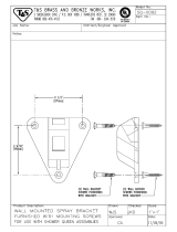
2. If
WA380 antennas are used, locate and mount the anten-
nas remotely as described in the instruction sheet. Use ei-
ther the mounting brackets supplied with the
WA420 exten-
sion cables for wall mounting, or a Shure Model
WA440
Rack Mount
Ki
for rack mounting the antennas, or Shure
Model A57 Swivel Adapters (or equivalent) if standard mi-
crophone stands are
used
to support the antennas.
3. Fully extend all telescoping sections of the
WA380 an-
tennas for optimum reception. Make sure that the ex-
tended antennas are vertical.
Connecting Receivers to the WA404*
1.
Connect the Antenna
Inputs of the receivers to the RF
Outputs of the
WA404 with the supplied
rf
cables.
2. Connect the receivers to the 15 Vdc outputs on the rear
panel of the
WA404 using the Power Interconnect
cables furnished. Note that the interconnect cables are
furnished with locking plugs that mate with the
WA404.
*Check power requirements before using with receivers made
by
other
manufacturers.
01996,
Shure Brothers Inc.
27A8350 (PA)
Printed in U.S.A.

Connecting Power to the WA404
1. Connect the WA404 to the power mains, using the cor-
rect power cable. For a 100 to 120 V power source
(WA404), use the standard three-prong grounded cable
supplied. For a 2201240 V power source
(WA404E), use
the cord with the CEE
717 ("Schuko") connector at the
mains end.
NOTE:
For systems requiring other mains connectors,
procure a power cord having an
IEC 320 type mating con-
nector to connect to the
WA404 and an appropriate plug
at the other end for connection to the mains. The supplied
cord uses Harmonized IEC Cordage with color coding as
follows:
Brown
=
Line
Blue
=
Neutral
GreenNellow
=
Ground
2. Press the POWER switch to turn the unit ON. The green
POWER LED on the front panel will light to indicate that
the unit is powered, and that power is being supplied to
any receivers connected.
Checking Operation
Test each microphoneltransmitter for optimum opera-
tion. Try different antenna locations to achieve the best per-
formance levels. Refer to the system instructions material for
additional information.
PLEASE NOTE
This product is not completely disconnected from the mains
supply when the power switch is off.
SPECIFICATIONS
RF Carrier Frequency Range
169 to 230 MHz
Gain
3.5 dB nominal
Antenna Input lmpedance
50
!2
nominal
RF Output lmpedance
50
!2
nominal
Power
100 to 120 Vac (WA404); 2201240 Vac (WA404E); 50160 Hz; 50W
(Typical)
DC Power Output
15 Vdc, 2 A maximum14 outlets (center pin is +)
Overall Dimensions
44.5 mm H x 435 mm W x 187 mm D (1 -314 in. H x 17-118 in. W
x 7-318 in. D)
Weight
1.95 kg (4 Ib 4.5 oz)
Certifications
WA404: Listed by U; listed by CSA as Certified. FCC Verified un-
der Part 15 as a Class B digital device.
WA404E: Approved for safety by VDE under DIN
VDE 0805105.90 harmonized with CENELEC EN 60
950: 1988
STATEMENT OF CONFORMITY:
This certifies that
the Shure
AntennaIPower Distribution System, WA404E,
meets the specifications and regulations embodied in Vfg
24311 991, amended 1 992. The Bundesamt
fijr Zulassun-
gen in der Telekommunikation has been notified that this
device has been marketed and has been provided the right
to verify the device or system for compliance with the speci-
fications.
INFORMATION TO USER:
Changes or modifications
not expressly approved by Shure Brothers
Inc. could void
your authority to operate this equipment.
This equipment has been tested and found to comply
with the limits for a Class B digital device pursuant to Part
15 of the FCC Rules and as set out in the Radio Interference
Regulations of the Canadian Department of Communica-
tions. These limits are designed to provide reasonable
protection against harmful interference in a residential
installation. This equipment generates, uses, and can radi-
ate radio frequency energy and,
if
nd installed and used in
accordance with the instructions, may cause harmful inter-
ference to radio communications. However, there is no
guarantee that interference will not occur in a particular
installation.
If
this equipment does cause harmful interfer-
ence to radio or television reception, which can be deter-
mined by turning the equipment off and on, the user is en-
couraged to try to correct the interference by one or more
of the following meaures:
1. Reorient or relocate the receiving antenna.
2. Increase the separation between the equipment and
receiver.
3. Connect the equipment into an outlet on a circuit differ-
ent from that to which the receiver is connected.
4. Consult the dealer or an experienced
radio/TV techni-
cian for help.
FURNISHED ACCESSORIES
Coaxial lnterconnecting RF Cable (8)
.............................
0.6m (2ft). 95B8217
.............
Interconnecting Power Cables (4) 95A8373
..................
Rack Mounting Brackets (2) 48A8012
Adhesive Bumpers (4)
.......................
66A8010
............
Line Cord, WA404, 100 to 120 Vac
95A8389
.............
Line Cord, WA404E, 2201240 Vac
95A8247
OPTIONAL ACCESSORIES
Antenna
..........................
169 to 185 MHz WA380A
..........................
185 to 200 MHz WA380B
.........................
200 to 230 MHz WA380C
Coaxial Antenna Cable Assembly,
..............................
6.1 m (20 ft) WA420
.......................
Antenna Rack-Mount Kit WA440
For additional service or parts information, please contact
Shure's Service department at 1-800-51 6-2525. Outside the
United States, please contact your authorized Shure Service
Center.
/