Page is loading ...

FPI FIREPLACE PRODUCTS INTERNATIONAL LTD. 6988 Venture St., Delta, BC Canada, V4G 1H4
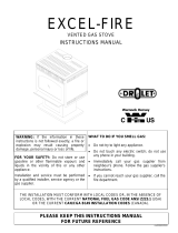
WARNING:
If the information in these instructions are not followed exactly,
a fire or explosion may result causing property damage,
personal injury or loss of life.
FOR YOUR SAFETY
Do not store or use gasoline or other flammable vapors and
liquids in the vicinity of this or any other appliance.
Installation and service must be performed by a qualified
installer, service agency or the gas supplier.
FOR YOUR SAFETY
What to do if you smell gas:
Do not try to light any appliance
Do not touch any electrical switch:
do not use any phone in your
building.
Immediately call your gas supplier
from a neighbour's phone. Follow
the gas supplier's instructions.
If you cannot reach your gas
supplier, call the fire department.
908-429a 04/21/05
EMERALD Gas Fireplace Insert
Owners &
Installation Manual
MODELS: E61-NG Natural Gas E61-LP Propane
www.waterfordstoves.com
Tested by:
Installer: Please complete the details on the back cover
and leave this manual with the homeowner.
Homeowner: Please keep these instructions for future reference.

2 Waterford E61 Gas Fireplace Insert
TO THE NEW OWNER
Congratulations! You are the owner of a state-of-the-art Gas Insert by Waterford Irish Stoves. The Waterford
Gas Fireplace Series of hand crafted appliances has been designed to provide you with all the warmth and
charm of a fireplace, at the flick of a switch. This series has been approved by Warnock Hersey for both safety
and efficiency. As it also bears our own mark, it promises to provide you with economy, comfort, and security
for many trouble free years to follow. Please take a moment now to acquaint yourself with these instructions
and the many features of your Waterford Fireplace.
WATERFORD GAS FIREPLACE INSERT
This appliance may be installed in an aftermarket permanently located, manufactured
(mobile) home, where not prohibited by local codes.
This appliance is only for use with the type of gas indicated on the rating plate. This appliance
is not convertible for use with other gases unless a certified kit is used.
Minor imperfections such as
blisters, seeds or thin flaws visible
in this product are not defects.
These are inherent in the hand-
crafted enamel process and cannot
be avoided, and they substantiate
that this is genuine porcelain
enamel.

3Waterford E61 Gas Fireplace Insert
TABLE OF CONTENTS
WATERFORD GAS FIREPLACE INSERT
Page Page
SAFETY LABEL
Safety Label.............................................................. 4
INSTALLATION REQUIREMENTS
For your safety ............................................................ 6
Gas Pipe Testing ........................................................ 6
Specifications ............................................................. 6
Zero Clearance Fireplace Installation .............................6
Installation into a Factory Built Fireplace..................... 6
Before You Start ......................................................... 6
General Safety Information .......................................... 6
Installation Checklist ................................................... 6
Materials Required ....................................................... 7
Clearances to Combustibles ........................................ 7
-Floor Protection .....................................................7
INSTALLATION INSTRUCTIONS
Gas Connection .......................................................... 8
System Data Table .......................................................8
High Elevation ...............................................................8
Venting .........................................................................8
Flue Liner Installation ....................................................9
Conversion from Nat. Gas to Propane............................ 9
Reduction to Lower Btu ...............................................11
Gas Pressure Test ......................................................11
Valve Description ........................................................12
Aeration System .........................................................12
Shroud Surround Installation .......................................12
Optional Door Grill Installation .....................................13
Log Installation............................................................13
Optional Wall Thermostat Installation ..........................13
Optional Remote Control Installation ...........................14
Wiring Diagram ......................................................... 14
OPERATING INSTRUCTIONS
Operating Instructions .................................................15
Lighting Procedure ......................................................15
Shutdown Procedure ...................................................15
First Fire .....................................................................15
Automatic Convection Fan Operation ..........................15
Normal Operating Sounds of Gas Appliances .............. 15
Copy of Lighting Plate Instructions ..............................16
MAINTENANCE
Maintenance ...............................................................16
Log Replacement and Cleaning ...................................17
Door Gasket and Glass Gasket ..................................17
Glass Replacement .....................................................17
Fan Maintenance ........................................................17
Valve Maintenance ......................................................18
Parts List ....................................................................19
WARRANTY
Warranty .....................................................................23

4 Waterford E61 Gas Fireplace Insert
This is a copy of the label that accompanies
each Waterford E61-NG Gas Insert Natural
Gas. We have printed a copy of the contents
here for your review. The safety label is located
on the right side door panel.
NOTE: Waterford units are constantly being
improved. Check the label on the unit and if there
is a difference, the label on the unit is the correct
one.
SAFETY LABEL
For the State of Massachusetts, installation
and repair must be done by a plumber or
gasfitter licensed in the Commonwealth of
Massachusetts.
For the State of Massachusetts, flexible
connectors shall not exceed 36 inches in
length.
For the State of Massachusetts, the appli-
ances individual manual shut-off must be a
t-handle type valve.
DUPLICATE SERIAL NO.
DO NOT REMOVE OR COVER THIS LABEL /
NE PAS ENLEVER CETTE TIQUETTEÉ
205
205
FPI Fireplace Products International Ltd., Delta, BC, Canada
Serial no./
No de serie
908-419b
Made in Canada/Fabrique au Canada
ÉÉQUIP A L'UISINE POUR GAZ NATURAL
5" WC/C.E. (1.25 kPa)
3.8" WC/C.E. (0.94 kPa)
1.1" WC/C.E. (0.27 kPa)
#33 DMS (2.87mm)
200
36,100 Btu/h (10.57 Kw/h)
18,000 Btu/h (5.28 Kw/h)
0-4500 ft/pi (610-1372m)
Minimum supply pressure
Manifold pressure High
Manifold pressure Low
Factory Equipped for Altitude 0-2000 ft.
Maximum Input
Minimum Input
Orifice size
Altitude
Convertible to 27,000 Btu for Altitude 0 - 4500 ft. with Kit #: 260-920
Maximum Input
Minimum Input
Orifice size
Altitude
Convertible for Altitude 2000-4500 ft.
Maximum Input
Minimum Input
Orifice size
Altitude
FACTORY EQUIPPED FOR NATURAL GAS Model:E61NG
Pression d'allimentation minimum
Pression la tubulure d' chappement lev e
Pression la tubulure d' chappement basse
à
à
ééé
é
38,000 Btu/h (11.14 Kw/h)
19,000 Btu/h (5.57 Kw/h)
#32 DMS (2.9mm)
0-2000 ft/pi (0-610m)
27,000 Btu/h (7.91 Kw/h)
13,500 Btu/h (3.95 Kw/h)
#40 DMS (2.49mm)
0-4500 ft/pi (0-1372m)
D bit Calorifique maximum
D bit Calorifique minimum
Dimensions de l'orifice
L'altitude
é
é
D bit Calorifique maximum
D bit Calorifique minimum
Dimensions de l'orifice
L'altitude
é
é
D bit Calorifique maximum
D bit Calorifique minimum
Dimensions de l'orifice
L'altitude
é
é
This appliance is only for use with the type of gas indicated on the rating plate and may be installed in an
aftermarket, permanenlty located,manufactured (mobile) home where not prohibited by local codes. See owner's
manual for details. This appliance is not convertible for use with other gases, unless a certified kit is used.
A
B
Minimum Clearances
to Combustibles/
Degagement Minimum
De Materiaux Combustibles
Unit to Sidewalls A 9"/230mm
Top of Hob to mantel:
unshielded B 16"/406mm
shielded B 12"/305mm
To ceiling from top of stove: 36"/ 915mm
A floor protector consisting of one layer of ½" thick
WonderBoard , Durock , or equivalent extending
at least 9" in front of the face of the unit and the full
width of the front surface is required.
Floor Protector
This appliance must be installed in accordance with
local codes, if any; if none, follow the National Fuel
Gas Code, ANSI Z223.1/NFPA 54, or Natural Gas and
Propane Installation Codes, CSA B149.1.
FOR USE WITH GLASS DOORS CERTIFIED
WITH APPLIANCE ONLY.
This vented gas fireplace heater is
not for use with air filters.
Not for use with solid fuel.
Electrical Supply (115 V, 1.13A, 60 Hz)
Approved for use with Emerald Zero Clearance Kit, Part No. 270-900.
Listed:
Report No.
VENT GAS FIREPLACE HEATER
476-1714-00 (Oct. 1999)
Certified for/Certifi e pour: CANADA and U.S.A.é
ANSI Z21.88b-2003/CSA 2.33b-2003, /CGA 2.17-M91Tested to: CAN

5Waterford E61 Gas Fireplace Insert
This is a copy of the label that accompanies
each Waterford E61-LP Gas Insert Propane.
We have printed a copy of the contents here for
your review. The safety label is located on the
right side door panel.
NOTE: Waterford units are constantly being
improved. Check the label on the unit and if there
is a difference, the label on the unit is the correct
one.
SAFETY LABEL
DUPLICATE SERIAL NO.
DO NOT REMOVE OR COVER THIS LABEL /
NE PAS ENLEVER CETTE TIQUETTEÉ
204
204
Serial no./
No de serie
908-438b
12" WC/C.E. (3.00 kPa)
11" WC/C.E. (2.74 kPa)
2.9" WC/C.E. (0.72 kPa)
Minimum supply pressure
Manifold pressure High
Manifold pressure Low
Factory Equipped for 35,000 Btu
Maximum Input
Minimum Input
Orifice size
Altitude
Convertible to 29,000 Btu for Altitude 0 - 4500 ft. with Kit #: 260-922
Maximum Input
Minimum Input
Orifice size
Altitude
FACTORY EQUIPPED FOR PROPANE Model:E61LP
Pression d'allimentation minimum
Pression la tubulure d' chappement lev e
Pression la tubulure d' chappement basse
à
à
ééé
é
35,000 Btu/h (10.26 Kw/h)
17,500 Btu/h (5.13 Kw/h)
#50 DMS (1.8mm)
0-2000 ft/pi (0-610m)
D bit Calorifique maximum
D bit Calorifique minimum
Dimensions de l'orifice
L'altitude
é
é
D bit Calorifique maximum
D bit Calorifique minimum
Dimensions de l'orifice
L'altitude
é
é
ÉÉQUIP A L'UISINE POUR GAZ PROPANE
29,000 Btu/h (8.50 Kw/h)
14,500 Btu/h (4.25 Kw/h)
#52 DMS (1.61mm)
0-4500 ft/pi (0-1372m)
Listed:
Report No.
VENT GAS FIREPLACE HEATER
476-1714-00 (Oct. 1999)
Certified for/Certifi e pour: CANADA and U.S.A.é
ANSI Z21.88b-2003/CSA 2.33b-2003, /CGA 2.17-M91Tested to: CAN
FPI Fireplace Products International Ltd., Delta, BC, Canada
Made in Canada/ Fabrique au Canada
This appliance must be installed in accordance with
local codes, if any; if none, follow the National Fuel
Gas Code, ANSI Z223.1/NFPA 54, or Natural Gas and
Propane Installation Codes, CSA B149.1.
FOR USE WITH GLASS DOORS CERTIFIED WITH
APPLIANCE ONLY.
This vented gas fireplace heater is not for
use with air filters.
Not for use with solid fuel.
Electrical Supply (115 V, 1.13A, 60 Hz)
This appliance is only for use with the type of gas indicated on the rating plate and may be installed in an
aftermarket, permanenlty located,manufactured (mobile) home where not prohibited by local codes. See owner's
manual for details. This appliance is not convertible for use with other gases, unless a certified kit is used.
A
B
Minimum Clearances
to Combustibles/
Degagement Minimum
De Materiaux Combustibles
Unit to Sidewalls A 9"/230mm
Top of Hob to mantel:
unshielded B 16"/406mm
shielded B 12"/305mm
To ceiling fromtop of stove: 36"/ 915mm
Approved for use with Emerald Zero Clearance Kit, Part No. 270-900.
Floor Protector
A floor protector consisting of one layer of ½" thick
WonderBoard , Durock , or equivalent extending
at least 9" in front of the face of the unit and the full
width of the front surface is required.

6 Waterford E61 Gas Fireplace Insert
INSTALLATION
INSTALLATION INTO
AFACTORY BUILT
FIREPLACE
The WATERFORD Gas Inserts have been test-
ed and approved to be vented into any ap-
proved Factory Built Fireplace that will allow
the Insert to physically fit into the firebox.
If the factory built fireplace height is too
low for your Insert, you may remove the
smoke shelf, baffle plate, and damper
plate from the factory built fireplace if
removable without cutting or torching,
as long as these items are saved and are
re-installed in the event that the Insert is
removed.
BEFORE YOU START
Safe installation and operation of this appliance
requires common sense, however, we are
required by the Canadian Safety Standards
and ANSI Standards to make you aware of the
following:
General Safety Information
1) The appliance installation must conform
with local codes or in the absence of local
codes, with current CAN/CGA B149 (in
Canada) or the current National Fuel Gas
Code ANSI Z223.1. This appliance MUST be
installed by a qualified gas fitter technician
only.
2) Installation and repair should be done
by a qualified service person.
3) The appliance should be inspected before
use and at least annually by a professional
service person. More frequent cleaning
may be required due to excessive lint from
carpeting, bedding material, etc. It is imper-
ative that control compartments, and circu-
lating air passageways of the appliance be
kept clean and free from excessive lint from
carpeting and pet hair.
4) See general construction and assembly
instructions. This appliance may only be
installed in a vented, non-combustible fire-
place.
5) This appliance may be installed into bed-
rooms when used with a Listed Millivolt
Thermostat. Some areas may have further
requirements, check local codes before
installation.
6) This unit is approved for installation into a
mobile home.
7) Always connect this fireplace to a chimney
and vent to the outside of the building
IMPORTANT:
SAVE THESE
INSTRUCTIONS
The Waterford Gas Fireplace must be installed
in accordance with these instructions. Careful-
ly read all the instructions in this manual first.
Consult the building authority having jurisdiction
to determine the need for a permit prior to
starting the installation.
Note: Failure to follow these instructions
could cause a malfunction of the
heater which could result in death,
serious bodily injury, and/or prop-
erty damage. Failure to follow these
instructions may also void your
fire insurance and/or warranty.
FOR YOUR SAFETY
This appliance requires air for proper combus-
tion. Always provide adequate combustion and
ventilation air. Follow instructions and informa-
tion in the current CAN/CGA B149 (in Canada)
or the current National Fuel Gas Code ANSI
Z223.1 (in the USA), regarding requirements for
combustion and ventilation air.
GAS PIPE TESTING
The appliance must be isolated from the gas
supply piping system by closing its individual
manual shutoff valve during any pressure test-
ing of the gas supply piping system at test
pressures equal to or less than 1/2 psig. (3.45
kPa).
SPECIFICATIONS
Fuel: Natural gas or Propane
Electrical: 120V A.C. system.
Fan/Blower: Variable speed, 140 CFM.
Log Sets: Ceramic fiber, 3 per set.
Vent System: Listed two 3" co-linear
aluminum flex liners.
ZERO CLEARANCE
INSTALLATION
The WATERFORD Gas Inserts are only ap-
proved for installation into the WATER-
FORD E61 Gas Insert Zero Clearance Fire-
place Kit, model #270-900.
NOTE: There are changes in clearances
and other differences when installing
into the Zero Clearance Kit. Read the Zero
Clearance Kit manual and the decal on the
Kit.
envelope. Never vent to another room or
inside a building. Make sure that the vent
is properly sized and is of adequate height
to provide the proper draft.
8) Inspect the venting system annually for
blockage and any signs of deterioration.
9) Any safety glass removed for servicing
must be replaced prior to operating the
appliance.
10)To prevent injury, do not allow anyone who
is unfamiliar with the operation to use the
fireplace.
11)Due to high temperatures, the appliance
should be located out of high traffic areas
and away from furniture and draperies.
Children and adults should be alerted to the
hazards of high surface temperatures,
especially the fireplace glass and gold
trims, and should stay away to avoid burns
or clothing ignition. Young children should
be carefully supervised when they are in
the same room as the appliance. Clothing or
other flammable material should not be
placed on or near the appliance.
12)WARNING: Failure to position the parts
in accordance with the diagrams in
this manual or failure to use only
parts specifically approved with this
appliance may result in property dam-
age or personal injury.
13)Do not use this appliance if any part has
been under water. Immediately call a qual-
ified service technician to inspect the ap-
pliance and to replace any part of the
control system and any gas control which
has been under water.
INSTALLATION
CHECKLIST
The Waterford Gas Insert is installed as listed
below.
1) Unit Location - check Clearances to Com-
bustibles on page 7.
2) Make the gas connections and electrical
connection for fan. See page 8.
3) Install the 3" flue liner to the sliding connec-
tor plate. See page 9.
4) Slide the unit half way into the fireplace.
Emissions from burning wood or gas could
contain chemicals known to the State of
California to cause cancer, birth defects or
other reproductive harm.

7Waterford E61 Gas Fireplace Insert
CLEARANCES TO
COMBUSTIBLES
The following clearances to combustibles must
be observed:
From Unit
Sides A 9" / 229 mm
Unit to Unprotected Mantel B 16" / 406 mm
Unit to Protected Mantel* B 12" / 305mm
*Mantel shield must have a 1" (25mm) air space
between the mantel and shield and a 1" (25mm)
gap between on the back of the shield and the
facing.
In addition to these clearances, adequate ac-
cessibility clearance for servicing and proper
operation must be maintained.
Do not in any way obstruct the air inlets that are
located on the front of the heater.
Combustible Mantels are permitted within the
shaded area.
Combustibles are permitted within
the shaded area, on either side.
5) Pull the vent connector plate through the
tapered brackets and fasten to the front
plate. See page 9.
6) Slide the unit fully into the fireplace and
level.
7) Test gas pressure, page 11. Check aera-
tion, page 12.
8) Assemble and install the shroud. See page
12.
9) Install Optional Door Grill. See page 13.
10)Install the log set. See page 13.
11)Install Optional Remote Control, and Op-
tional Wall Thermostat, if required. See
pages 13 and 14.
12)Explain controls to the homeowner.
15)Final check: Before leaving this unit with
the customer, the installer must ensure that
the appliance is firing correctly. This in-
cludes:
a) Clocking the appliance to ensure the
correct firing rate.
b) Adjusting the primary air, if required, to
ensure that the flame does not carbon.
See page 12.
c) Ensuring that the appliance is venting
correctly.
MATERIALS
REQUIRED
No electrical power supply is required for the
gas control to operate. A 120 Volt AC power
cord is hooked up to the fan switch and blower.
Plug 3 wire cord into a suitable receptacle. Do
not cut the ground terminal off under any
circumstances.
When connected with 120 volts, the appliance
must be electrically grounded in accordance
with local codes, with a current version of CSA
C22.1 (in Canada) or in the absence of local
codes, with the National Electrical Code ANSI/
NFPA 70-1987.
Note: This unit is equipped with a heat
sensor thermodisc which will
prevent the blower from operat-
ing until the unit reaches the cor-
rect temperature.
INSTALLATION
WARNING:
Electrical Grounding Instructions
This appliance is equipped with a
three pronged (grounding) plug
for your protection against shock
hazard and should be plugged
directly into a properly grounded
three-prong receptacle. Do not cut
or remove the grounding prong
from this plug.
Floor Protection
An approved floor protector is required con-
sisting of a layer of 1/2" (13mm) Wonderboard
(or Durock or equivalent) that extends 9"
(229mm) in front of the fireplace measured at
the base (this equals 16" from the fireplace
opening), and as wide as the appliance.
Note: If the appliance is installed in a
fireplace that is elevated 5"
(127mm) or higher (i.e., a Water-
ford Zero Clearance Cabinet, zero
clearance fireplace, brick plinth,
etc.), no floor protection is re-
quired in front of the appliance.
When the Insert is installed in a fireplace that is
elevated 5" or higher, no floor protection is
required in front of the appliance.

8 Waterford E61 Gas Fireplace Insert
INSTALLATION
VENTING
THE APPLIANCE MUST NOT BE CON-
NECTED TO A CHIMNEY FLUE SERV-
ING A SEPARATE SOLID FUEL BURN-
ING APPLIANCE.
This appliance is designed to be attached to two
3" (76mm) co-linear aluminium flex running the
full length of the chimney. The flue length must
be a minimum length of 8' (2.44m) and a maxi-
mum of 35' (10.7m). See chart for minimum
distances from roof. Periodically check that the
vent is unrestricted.
Masonry chimneys may take various contours
which the flexible liner will accommodate. How-
ever, keep the flexible liner as straight as
possible, avoid unnecessary bending.
HIGH ELEVATION
This unit is approved in Canada (CAN/CGA-
2.17-M91) for altitudes to 2000 ft. (610m) using
the factory -installed burner orifice. For instal-
lations from 2000 ft (610m) to 4500 ft (1370m)
the orifice sizes (DMS) for the Natural Gas and
Propane units must be changed. See the rating
plate for details. For installations above 4500 ft.
refer to current ANSI Z223.1 Sc8-8.1.2a ap-
pendix F or CAN/CGA-B149.1, for resizing
orifice.
GAS CONNECTION
The Emerald Insert is factory equipped to burn
Natural Gas, if necessary the unit can be
converted to burn Propane by using Conver-
sion Kit # 260-960. For minimum and maximum
supply pressure see the System Data table on
page 8.
Note: Prior to any pressure testing of
the gas supply piping system that
exceeds test pressures of 1/2
psig, this appliance and its individ-
ual shut-off valve must be discon-
nected from the piping system. If
test pressures equal to or less
than 1/2 psig are used then this
appliance must be isolated from
the piping system by closing its
individual manual shut-off valve
during the testing.
GAS CONNECTION WARNING:
Only persons licensed to work with gas piping
may make the necessary gas connections to
this appliance.
1) The gas inlet is located on the end of the
flexible pipe that emerges from the lower
left rear corner of the unit. The inlet fitting is
a 1/2" female flare.
A separate gas shut-off valve and a 1/8" IPS
plugged tapping should be installed immedi-
ately upstream of the connection to the
appliance.
2) The gas inlet is located on the end of the
flexible pipe that emerges from the lower
left rear corner of the unit. The inlet fitting is
a 1/2" female flare.
A separate gas shut-off valve and a 1/8" IPS
plugged tapping should be installed immedi-
ately upstream of the connection to the
appliance.
3) Locate the center point where the vent will
pass through the chimney above the appli-
ance. Move the appliance into the exact
location where it is to be installed. Ensure
that the Insert is level.
4) The gas control valve is provided with two
"IN" and "OUT" pressure taps, and are
easily accessible for a test gauge connec-
tion (see diagram on page 12).
5) Once the gas has been connected ensure
that the pilot valve is in line with burner.
CAUTION: If the door is removed or
opened for servicing, it must be replaced
and closed prior to operating the appli-
ance. The glass must be fixed in the door
when operating.
Recommended Gas Pipe Diameter
Pipe Schedule 40 Tubing,
Length Pipe Type L
(feet) Inside Diameter Outside Diameter
NG LP NG LP
0 - 10 1/2" 3/8" 1/2" 3/8"
1.3cm 1.0cm 1.3cm 1.0cm
10 - 40 1/2" 1/2" 5/8" 1/2"
1.3cm 1.3cm 1.6cm 1.3cm
40 - 100 1/2" 1/2" 3/4" 1/2"
1.3cm 1.3cm 2.0cm 1.3cm
100 - 150 3/4" 1/2" 7/8" 3/4"
2.0cm 1.3cm 2.3cm 2.0cm
Note: Never use plastic pipe. Check to confirm
whether your local codes allow copper tubing
or galvanized pipe.
System Data:
E61 Converted to
27,000 (Natural Gas)
or 29,000 (Propane)
For 0 to 4500 feet altitude
Burner Inlet Orifice Sizes:
Natural Gas Propane
Burner #40 #52
Max. Input Rating
- Natural Gas 27,000 Btu/h
- Propane 29,000 Btu/h
Min. Input Rating
- Natural Gas 13,500 Btu/h
- Propane 14,500 Btu/h
Output Capacity with blower Off
Natural Gas 21,168 Btu/h
Propane 23,258 Btu/h
Output Capacity with blower On
Natural Gas 21,708 Btu/h
Propane 23,925 Btu/h
Supply Pressure
Natural Gas min. 5.0" w.c.
Propane min. 12.0" w.c.
Manifold Pressure
Natural Gas 3.8" +/- 0.2" w.c.
Propane 11" +/- 0.2" w.c.
System Data
For 0 to 2000 feet altitude
Burner Inlet Orifice Sizes:
Natural Gas Propane
Burner #32 #50
Max. Input
- Natural Gas 38,000 Btu/h
- Propane 35,000 Btu/h
Min. Input
- Natural Gas 19,000 Btu/h
- Propane 17,500 Btu/h
Max. Output Capacity with blower On
Natural Gas 30,666 Btu/h
Propane 28,700 Btu/h
Supply Pressure:
Nat. Gas min. 5" w.c. (1.25 kPa)
Propane min. 12" w.c. (3.0 kPa)
Manifold Pressure
Natural Gas 3.8" +/- 0.2" w.c. (0.94 kPa)
Propane 11" +/- 0.2" w.c. (2.7 kPa)
System Data - HIGH ELEVATION
For 2,000 - 4,500 feet altitude
Burner Inlet Orifice Sizes:
Natural Gas
Burner #33
Max. Input .
- Natural Gas 36,100 Btu/h

9Waterford E61 Gas Fireplace Insert
CONVERSION KIT
FROM NATURAL GAS
TO PROPANE MODEL
#260-960
for Emerald E61 Gas Insert
using SIT 820 NOVA Gas Valve
THIS CONVERSION MUST BE
DONE BY A QUALIFIED
GAS FITTER
IF IN DOUBT DO NOT DO THIS
CONVERSION !!
Conversion Kit Contains:
Qty.Part # Description
1 910-018 SIT Conversion Kit-50%
Turndown LP
1 910-383 LP Injector (Pilot Orifice)
1 904-641 Burner Orifice #50
1 908-455 Decal "Converted to Propane"
1 908-528 Red "PROPANE" label
1 908-173 Instruction Sheet
1) Shut off the gas supply.
2) Open the lower grill and remove the 2
screws holding the control panel in place.
Remove the 2 screws holding the
Control Panel in place.
FLUE LINER
INSTALLATION
1) Cut the flex liner as required.
2) Mark the end of one liner to indicate
Inlet.
3) Connect the other end of the above liner to
the inlet side of the termination adaptor, seal
connection with high temperature silicone.
Secure with gear clamp.
4) Connect the 2nd liner to the exhaust side of
the adaptor, seal connection with high tem-
perature silicone. Secure with gear clamp.
5) Install flashing.
6) Insert both liners into chimney, passing
through the damper opening.
7) Install termination cap.
8) Connect the marked end of the liner to
the inlet collar of the vent connector plate
marked with an "I", seal connection with
high temperature silicone. Secure with
gear clamp.
9) Connect the 2nd liner to the exhaust collar
marked with an "E", seal connection with
high temperature silicone. Secure with
gear clamp.
Part # Description
948-305 3" Flex - 35 ft.
946-529 Co-linear DV Vertical
Termination Cap
Alternate Approved Caps
980 Vertical Termination Cap
991 High Wind Cap
923GK 3" Co-linear Adaptor with flashing
In areas on consistently high winds, we recom-
mend using the Simpson Dura-Vent System
(923GK adapter and 991 high-wind cap).
The Air Intake pipe must be attached to the inlet
air collar of the termination cap.
INSTALLATION
NOTE:
1) Final gas connection should be made
after unit is in place to avoid damage to
line when pushing the unit into position.
2) Mill-pac may be used instead of high
temperature silicone and screws may
be used instead of gear clamps at con-
nections of liner to inlet and vent col-
lars.
10)Attach the top shield to the top front lip of
the firebox using 3 screws.

10 Waterford E61 Gas Fireplace Insert
INSTALLATION
Pilot assembly is now accessible for
steps 6) to 11).
3) Remove the door by lifting it slightly up and
off the front face. Remove the 7 nuts that
secure the front glass bracket holding the
center glass in place.
Remove the 7 nuts holding the Front Glass
Bracket to the front face.
CAUTION: Don't let the glass drop.
4) Carefully remove the logs and embers.
5) Remove burner. See diagram below.
Note: Use a magnetic type screwdriver if
possible.
6) Remove and discard the 3 pressure regu-
lator mounting screws (A), pressure regu-
lator tower (B) and diaphragm (C).
7) Insure that the rubber gasket (D) is properly
positioned and install the new HI/LO pres-
sure regulator assembly to the valve using
the new screws (E) supplied with the kit.
Tighten screws securely.
8) Pull off the pilot cap to expose the pilot
orifice.
9) Unscrew the pilot orifice with the allen key
and replace with the LP pilot orifice in the kit.
10)Remove burner orifice with a 1/2" wrench
and discard. Use a wrench to hold on to the
elbow behind the orifice.
11)Reinstall new burner orifice LP stamped
#50 and tighten.
12)Reverse steps 5) to 1).
13)Attach the label (Part#: 908-455) "This unit
has been converted to Propane" on top of
the Serial # decal.
14) Replace yellow "Natural Gas" label with red
"Propane" label
15)Check for gas leaks.
16)Check inlet and outlet pressures.
17)Check operation of flame control.
18)Check for proper flame appearance and
glow on logs.

11Waterford E61 Gas Fireplace Insert
Reduction Kit to Lower
Btu Rating for Emerald
E61 Gas Insert
Natural Gas - Kit #: 260-920
Propane - Kit # 260-922
THIS CONVERSION MUST BE
DONE BY A QUALIFIED
GAS FITTER
IF IN DOUBT DO NOT DO THIS
CONVERSION !!
Natural Gas Conversion Kit 260-920
Contains:
Qty.Part # Description
1 904-593 Burner Orifice #40 (Natural Gas)
1 908-365 Decal "Converted to 27,000 Btu"
1 908-363 Instruction Sheet
Propane Conversion Kit 260-922 Contains:
Qty.Part # Description
1 904-390 Burner Orifice #52 (Propane)
1 908-366 Decal "Converted to 29,000 Btu"
1 908-363 Instruction Sheet
1) Shut off the gas supply.
2) Open the lower grill and remove the 2
screws holding the control panel in place.
Burner Orifice
3) Remove the door by lifting it slightly up and
off the front face. Remove the 7 nuts that
secure the front glass bracket holding the
center glass in place.
Remove the 2 screws holding the
Control Panel in place.
Remove the 7 nuts holding the Front Glass
Bracket to the front face.
CAUTION: Don't let the glass drop.
INSTALLATION
4) Carefully remove the logs and embers.
5) Remove burner.
Note: Use a magnetic type screwdriver
if possible.
6) Remove burner orifice with a 1/2" wrench
and discard.
7) Reinstall new burner orifice (NG stamped
#40 or LP stamped #52) and tighten.
8) Reverse steps 5) to 1).
9) Attach the label "This unit has been con-
verted to..." on top of the Serial # decal over
the higher Btu information.
10)Check for gas leaks.
11)Check inlet and outlet pressures.
12)Check operation of flame control. Check
for proper flame appearance and glow on
logs.
GAS PIPE PRESSURE
TESTING
The appliance must be isolated from the gas
supply piping system by closing its individual
manual shut-off valve during any pressure
testing of the gas supply piping system at test
pressures equal to or less than 1/2 psig. (3.45
kPa). Disconnect piping from valve at pres-
sures over 1/2 psig.
The unit is preset to give the correct gas input
at the specified manifold pressures shown on
the label. The maximum gas manifold pressure
is:
Natural Gas: 3.8" w.c.
Propane: 11" w.c.
The manifold pressure is controlled by a reg-
ulator built into the gas control, and should be
checked at the pressure test point. The pres-
sure check should be carried out with the unit
burning and the setting should be with in the
limits specified.
Note: To properly check gas pressure,
both inlet and manifold pressures
should be checked using the valve
pressure ports on the valve.
1) Make sure the valve is in the "OFF" position.
2) Loosen the "IN" and/or "OUT" pressure
tap(s), turning counterclockwise with a 1/
8" wide flat screwdriver.
3) Attach manometer to "IN" and/or "OUT"
pressure tap(s) using a 5/16" ID hose.
4) Light the pilot and turn the valve to "ON"
position. Read manometer.
5) The pressure check should be carried out
with the unit burning and the setting should
be within the limits specified on the safety
label.
6) When finished reading manometer, turn off
the gas valve, disconnect the hose and
tighten the screw (clockwise) with a 1/8"
flat screwdriver. Note: Screw should be
snug, but do not over tighten

12 Waterford E61 Gas Fireplace Insert
INSTALLATION
SHROUD
INSTALLATION
1) Attach the 2 side Surround Panels to the
body. Each side panel attaches to the body
with two bolts per side (top and bottom) and
use a washer and a 1/2" spacer with each
screw.
2) Plug the 'quick connect' electrical connec-
tion into the junction box. An alternative
wire outlet is provided on the junction box
so that the blower power cable can be
routed out the back of the shroud if so
desired.
Alternate
wiring port
Top Surround Panel
Retaining Bracket
Side panel with
1/2" spacer
Rear View: Side
panel attached
with 2 bolts.
AERATION
ADJUSTMENT
The burner aeration is factory set but may need
adjusting due to either the local gas supply, air
supply or altitude.
with 38,000 Btu with 27,000 (NG) /
29,000 LP
Natural Gas Natural Gas
3/16"(4.75mm) 1/8"(3.18mm)
Propane Propane
1/4"(6.35mm) 3/16" (4.75mm)
1) Turn the heater off and allow it to cool.
2) Open the bottom door.
Closed - Tall yellow flame
Open - Short blue flame
Allen Key
3) To adjust the aeration: use the allen key to
turn the turning gear which will adjust the
air shutter. Open the air shutter for a blue
flame or close it for a yellower flame.
Valve Description
1) Gas cock knob
2) Manual high/low adjustment
3) Pilot Adjustment
4) Thermocouple Connection
5) Main Operator
6) Outlet Pressure Tap (Manifold Pressure)
7) Inlet Pressure Tap (Supply Pressure)
8) Pilot Outlet
9) Main Gas Outlet
10)Flange Securing Screw Holes
11)Alternative TC Connection Point
12)Thermoelectric Unit
13)Additional Valve Mounting Hole
4) Restart the heater and let it burn for approx-
imately 15 minutes. Repeat until the desired
flame appearance is achieve.
Caution: Carbon will be produced if the
air shutter is closed too much.
Note: Any damage due to carboning re-
sulting from improperly setting
the aeration controls is NOT cov-
ered under warranty.
Note: Aeration Adjustment should only
be performed by an authorized
Regency Installer at the time of
installation or service.
3) Connect the Hob to the Top Surround Panel.
The Hob is attached with 2 bolts (with
washers) on either side.
4) The Hob & Top Surround Panel will be placed
in position as the last step of the installation.
The flue spillage test and fitting the draft
hood are more easily accomplished without
the Hob & Top Surround Panel in position.
When ready to install the Hob & Top Sur-
round Assembly, lower it down onto the top
of the body. It is held in place by its own
weight and the retaining brackets on each
side.
Oversize
Shroud Only: The
4 retaining brack-
ets on the Top Sur-
round must be re-
moved and rotated
180
o
and replaced.
The end of the
bracket must ex-
tend beyond the
bottom of the Top
Surround.

13Waterford E61 Gas Fireplace Insert
5) Place the two Small Side Logs beside the
burner on the firebox floor, as shown in
diagram 4.
6) Distribute the embers along the front burner
but do not cover the burner ports and
around the logs. Place the embers on the
floor of the firebox. Place the lava on the
burner tray in front of the left and right front
logs. See Diagram 4.
Diagram 4
Diagram 3
Diagram 1: Do not force logs down.
Diagram 2
3) Place the left front log, carefully sliding it
down onto the left pins of the front burner.
See diagram 2.
LOG INSTALLATION
WARNING: Dangerous operating
conditions may occur if these logs
are not positioned in their approved
locations. Read the instructions
below carefully and refer to the
diagrams. If logs are broken do not
use the unit until they are replaced.
Broken logs can interfere with the
pilot and burner operation.
OPTIONAL DOOR
GRILL
1) Remove the door by lifting it slightly up and
off the front face.
Secure the Door Grill to the
Door with 2 screws.
INSTALLATION
2) Remove the 2 side screws.
3) Position the door grill inside the door and
secure with the 2 screws.
4) Place the right front log, carefully sliding it
down onto the right pins of the front burner.
See diagram 3.
a) Front Right Log - Part # 902-020
b) Front Left Log - Part # 902-021
c) Rear log - Part # 902-022
d) Embers - Part # 902-151 (1 bag)
e) Lava - Part # 902-154 (1 bag)
(Part # 560-935 for the set of three logs)
1) Remove the logs from the box and carefully
unwrap them. The logs are fragile, handle
with care - DO NOT FORCE into position.
2) Place the rear log, carefully sliding it down
onto the pins, with the flat side of the log
facing the back of the unit. See diagram 1.
OPTIONAL WALL
THERMOSTAT
A wall thermostat may be installed if desired.
Connect the wires as per the wiring diagrams.
Note that the wires are connected to the "TH"
on the gas valve. Use table below to determine
the maximum wire length:
Note: Preferable if the thermostat is in-
stalled on an interior wall.
Waterford offers an optional programmable
thermostat but any 250-750 millivolt rated non-
anticipator type thermostat that is CSA, ULC or
UL approved may be used.
CAUTION
Do not connect the millivolt
wall thermostat wires
to the 120V wires.
Thermostat Wire Table
14 GA.
16 GA.
18 GA.
20 GA.
22 GA.
50 Ft.
32 Ft.
20 Ft.
12 Ft.
9 Ft.
Recommended Maximum Lead Length
(Two-Wire) When Using Wall
Thermostat (CP-2 System)
Wire Size Max. Length

14 Waterford E61 Gas Fireplace Insert
INSTALLATION
WIRING DIAGRAM
This heater does not require a 120V A.C.
supply for operation. In case of a power failure,
the burner switch and the optional remote
control/thermostat will continue to operate.
However, a 120V A.C. power supply is needed
for the fan/blower operation.
Caution: Ensure that the wires do
not touch any hot surfaces and are
away from sharp edges.
Verify proper operation after serv-
icing.
OPTIONAL REMOTE
CONTROL
Use the Waterford Remote Control Kit approved
for this unit. Use of other systems may void your
warranty.
The remote control kit comes with a hand held
transmitter, a receiver and a wall mounting
plate.
1) Choose a convenient location on the wall to
install the receiver and the receptacle box
(protection from extreme heat is very im-
portant). Run wires from the fireplace to
that location, use Thermostat Wire Table.
2) Connect the wires as per the wiring dia-
gram below.
CAUTION
Do not connect the millivolt
remote control wires to the
120V wires.
3) Install 3 AAA alkaline batteries in transmit-
ter and 4 AA alkaline batteries in the
receiver. Install the receiver and its cover
in the wall. Switch the remote receiver to
"remote" mode. The remote control is now
ready for operation.
If any of the original wires as supplied
with the appliance must be replaced, it
must be replaced with CSA type SEW
(200
o
C) or its equivalent.
CAUTION: Label all wires prior to dis-
connection when servicing controls.
Wiring errors can cause improper and
dangerous operation.
WARNING: Electrical Grounding Instructions
This appliance is equipped with a three pronged (grounding) plug for your protection
against shock hazard and should be plugged directly into a properly grounded three-
prong receptacle. Do not cut or remove the grounding prong from this plug.

15Waterford E61 Gas Fireplace Insert
OPERATING INSTRUCTIONS
OPERATING
INSTRUCTIONS
Before operating this appliance, proceed
through the following check list.
1) Read and understand these Instructions
before operating this appliance.
2) Check to see that all wiring is correct and
enclosed to prevent possible shock.
3) Check to ensure there are no gas leaks.
4) Make sure the three door glass pieces are
in place. Never operate the appliance with
any of the door glass removed or with the
door open. Do not strike the glass or slam
the door shut.
WARNING: Do not operate appli-
ance with glass front removed,
cracked or broken. Replacement of
the glass should be done by a li-
censed or qualified service person.
5) Verify that all venting and the cap is unob-
structed.
6) Verify log placement. If the pilot cannot be
seen when lighting the unit - the logs or the
embers have been incorrectly positioned.
7) The unit should never to turned off and on
without a minimum of a 60 second wait.
8) When lighting the appliance, the inside of
the glass may fog up. This will burn off after
a few minutes of operation.
DO NOT BURN THE APPLIANCE
WITH THE DOOR OPEN.
LIGHTING PROCEDURE
IMPORTANT: Gas cock knob cannot be turned
from "PILOT" to "OFF" unless it is partially
depressed.
1) Open the lower grill.
2) If the control knob is set to "OFF" proceed
to Step 4.
3) Push in gas control knob slightly and turn
clockwise to "OFF".
4) Wait five minutes to allow gas, that may
have accumulated in the main burner com-
partment, to escape. If you do smell gas,
follow the instructions on the front of this
manual. If you don't smell gas continue on
to the next step.
5) Turn the gas control counterclockwise to
"PILOT". Knob cannot be turned from "PI-
LOT" to "OFF" unless knob is pushed in
slightly. Do not force.
6) Push in control knob all the way and hold in.
Immediately push black button on spark
igniter until pilot lights. Continue to hold the
control knob in for approximately one
minute, then release the gas control knob.
The pilot flame should continue to burn. If
the pilot does not remain lit, repeat opera-
tion allowing a longer period before releas-
ing gas control knob.
7) Turn gas control knob counterclockwise to
"ON".
8) Use rocker switch to operate main burner.
9) Rotate the variable flame control to adjust
the flame height higher or lower.
10)Close the lower grill.
11)The door must be closed when operating
the unit.
SHUTDOWN
PROCEDURE
1) Use the rocker switch to turn off the main
burner.
2) Open the lower grill.
3) Push in the gas control knob slightly and
turn clockwise to "OFF". Do not force.
4) Disconnect all electric power to the appli-
ance if service is to be performed.
FIRST FIRE
The first fire in your stove is part of the paint
curing process. To ensure that the paint is
properly cured, it is recommended that you
burn your fireplace for at least four (4) hours
the first time you use it with the fan on.
When first operated, the unit will release an
odour caused by the curing of the paint, the
burning off of any oils remaining from manufac-
turing. Smoke detectors in the house may go off
at this time. Open a few windows to ventilate
the room for a couple of hours.
The glass panel may require cleaning after the
unit has cooled down. DO NOT ATTEMPT TO
CLEAN THE GLASS WHILE IT IS HOT.
AUTOMATIC
CONVECTION FAN
OPERATION
The fan operates automatically, turn the knob on
the side of the faceplate to adjust to the desired
speed. The fan will turn on as the stove comes
up to operating temperature. After the unit has
been turned off and the unit cooled to below a
useful heat output range the fan will shut off
automatically.
NORMAL OPERATING
SOUNDS OF
GAS APPLIANCES
It is possible that you will hear some sounds
from your gas appliance. This is perfectly nor-
mal due to the fact that there are various gauges
and types of steel used within your appliance.
Listed below are some examples. All are nor-
mal operating sounds and should not be
considered as defects in your appliance.
Blower:
Waterford gas appliances use high tech blow-
ers to push heated air farther into the room. It is
not unusual for the fan to make a "whirring"
sound when ON. This sound will increase or
decrease in volume depending on the speed
setting of your fan speed control.
Burner Tray:
The burner tray is positioned directly under the
burner and logs and is made of a different gauge
material from the rest of the firebox and body.
Therefore, the varying thicknesses of steel will
expand and contract at slightly different rates
which can cause "ticking" and "cracking"
sounds. You should also be aware that as there
are temperature changes within the unit these
sounds will likely re-occur. Again, this is normal
for steel fireboxes.
Blower Thermodisc:
When this thermally activated switch turns ON
it will create a small "clicking" sound. This is the
switch contacts closing and is normal.
Pilot Flame:
While the pilot flame is on it can make a very slight
"whisper" sound.
During the first few fires, a white film
may develop on the glass front as part
of the curing process. The glass should
be cleaned or the film will bake on and
become very difficult to remove. Use a
non-abrasive cleaner and NEVER clean
the glass while it is hot.

16 Waterford E61 Gas Fireplace Insert
OPERATING INSTRUCTIONS
COPY OF THE
LIGHTING PLATE INSTRUCTIONS
Gas Control Valve:
As the gas control valve turns ON and OFF, a
dull clicking sound may be audible, this is normal
operation of a gas regulator or valve.
Unit Body/Firebox:
Different types and thicknesses of steel will
expand and contract at different rates resulting
in some "cracking" and "ticking" sounds will be
heard throughout the cycling process.
MAINTENANCE
INSTRUCTIONS
1) Always turn off the gas valve before clean-
ing. For re-lighting, refer to lighting instruc-
tions. Keep the burner and control compart-
ment clean by brushing and vacuuming at
least once a year.
When cleaning the logs, use a clean soft
paint brush as the logs are fragile and easily
damaged.
2) Clean glass (never when unit is hot), appli-
ance, door and louvers with a damp cloth.
Never use an abrasive cleaner.
The heater is finished in a heat resistant
paint and should only be refinished with
heat resistant paint (not with wall paint).
Waterford uses Stove Brite Paint - Metallic
Black #6309.
3) Make a periodic check of burner for proper
position and condition. Visually check the
flame of the burner periodically, making
sure the flames are steady; not lifting or
floating. If there is a problem, call a qualified
service person.
4) The appliance and venting system must be
inspected before use, and at least annually,
by a qualified field service person, to en-
sure that the flow of combustion and ven-
tilation air is not obstructed.
During the annual service call, the burner
should be removed from the burner tray and
cleaned. Replace the embers but do not
block the pilot.
5) Verify proper operation after servicing.
6) Keep the area near the appliance clear and
free from combustible materials, gasoline
and other flammable vapours and liquids.
CAUTION: ANY SAFETY SCREEN
OR GUARD REMOVED FOR SERV-
ICING AN APPLIANCE MUST BE
REPLACED PRIOR TO OPERAT-
ING THE APPLIANCE.
TO TURN OFF GAS APPLIANCE
FOR YOUR SAFETY READ BEFORE LIGHTING
4)Push in control knob all the way and
hold in. Continually push and release
the black button on spark igniter until
pilot lights. Continue to hold the
control knob in for about 1/2 minute
after the pilot is lit. Release knob and
it will pop back up. Pilot should remain
lit. If it goes out, repeat steps 1) to 4).
If knob does not pop up when released,
stop and immediately call your service
technician or gas supplier. If the pilot will
not stay lit after several tries, turn the gas
control knob to “OFF” and call your
service technician or gas supplier.
STOP! Read the safety information
above on this label.
1) Push in gas control knob slightly and
turn clockwise to “OFF”. Knob
cannot be turned from “PILOT” to “OFF”
unless knob is pushed in slightly. Do
not force.
2) Wait five (5) minutes to clear out any
gas. If you then smell gas STOP! follow
“B” in the safety information above on
this label. If you don’t smell gas, go to
the next step.
3)Turn knob on gas control counter-
clockwise to“PILOT”.
1) Push in the gas control knob slightly and
turn clockwise to “OFF”. Do not force.
CAUTION: Hot while in operation. Do not touch. Severe Burns may result. Due
to high surface temperatures keep children, clothing and furniture, gasoline
and other liquids having fammable vapors away. Keep burner and control
compartment clean. See installation and operating instructions
accompanying appliance.
LIGHTING INSTRUCTIONS
5)Turn gas control knob
counterclock-wise
to “ON”.
6)Use rocker switch to op-
erate main burner.
A)This appliance has a pilot which
must be lighted by hand. When
lighting the pilot, follow these
instructions exactly.
B)BEFORE LIGHTING smell all around
the appliance area for gas. Be sure to
smell next to the floor because some
gas is heavier than air and will settle
on the floor.
WHAT TO DO IF YOU SMELL GAS
- Do not try to light any appliance
- Do not touch any electric switch, do
not use any phone in your building
- Immediately call your gas supplier
from a neighbours phone. Follow the
gas supplier’s instructions.
- If you cannot reach your gas supplier,
call the fire department.
C)Use only your hand to push in or turn
the gas control knob. Never use tools.
If the knob will not push in or turn by
hand, don’t try to repair it, call a qualified
service technician. Force or attempted
repair may result in a fire or explosion.
D)Do not use this appliance if any part has
been under water. Immediately call a
qualified service technician to inspect the
appliance and to replace any part of the
control system and any gas control which
has been under water.
This appliance needs fresh air for safe
operation and must be installed so there are
provisions for adequate combustion and
ventilation air.
DO NOT REMOVE THIS INSTRUCTION PLATE
WARNING: If you do not follow these instructions exactly, a fire or
explosion may result causing property damage, personal injury or loss
of life. Improper installation, adjustment, alteration, service or maintenance
can cause injury or property damage. Refer to the owner’s information
manual provided with this appliance. For assistance or additional
information consult a qualified installer, service agency or gas supplier.
OFF
ELEMENT
THERMO-
ELECTRIQUE
VEILLEUSE
PILOT BURNER
THERMOPILE
908-017b
2)Turn off all electric power to the
appliance if service is to be performed.
You may shut off the pilot during prolonged non use periods to conserve fuel.
This appliance must be installed in accordance with local codes, if any; if none, follow the
National Fuel Gas Code, ANSI Z223.1/NFPA 54, or Natural Gas and Propane Installation
Codes, CSA B149.1. (Australia: AG601, New Zealand: NZS 5261)

17Waterford E61 Gas Fireplace Insert
FAN MAINTENANCE
If your fan requires maintenance or replace-
ment, access to the fan is through the plate on
the rear wall of the firebox. NOTE: the unit
MUST NOT be operated without the fan
access panel securely in place and cor-
rectly sealed.
IMPORTANT: These fans collect a
lot of dust from within your home.
Ensure you maintain these fan mo-
tors on a regular basis by vacuum-
ing out the fan squirrel cages, around
the motor, and around the grills on
the back of the stove.
Remove the 7 nuts holding the
Front Glass Bracket to the front face.
CAUTION: Don't let the glass drop.
Top View of pilot flame
Top View of pilot flame
Incorrect flame pattern will have small, probably
yellow flames, not coming into proper contact
with the rear of the burner or thermopile.
LOG REPLACEMENT &
CLEANING
The unit should never be used with broken logs.
Turn off the gas valve and allow the unit to cool
before opening door to carefully remove the
logs. The pilot light generates enough heat to
burn someone. If for any reason a log should
need replacement, you must use the proper
replacement log. The position of these logs must
be as shown in the diagram under Log Installa-
tion.
NOTE: Improper positioning of
logs may create carbon build-up
and will alter the unit’s perform-
ance which is not covered under
warranty.
Cleaning the Log Set and Firebox
During the annual inspection and maintenance
appointment, the service person should clean
dust, lint, and any light accumulation from the
logs and firebox area. An extra-soft brush
should be use don the logs as they are extreme-
ly fragile; a vacuum cleaner may be used on the
firebox. See the log installation instructions for
details on removing and replacing the logs.
DOOR AND GLASS
GASKET
If the door gasket requires replacement use only
the proper replacement gasket available from
your Waterford dealer.
GLASS REPLACEMENT
Your Waterford stove is supplied with high
temperature, 5 mm Neoceram ceramic glass
that will withstand the highest heat that your unit
will produce. In the event that you break your
glass by impact, purchase your replacement
from an authorized Waterford dealer only, and
follow our step-by-step instructions for re-
placement.
1) Remove the door by lifting it slightly up and
off the front face.
MAINTENANCE
WARNING: CHILDREN AND
ADULTS SHOULD BE ALERTED
TO THE HAZARDS OF HIGH SUR-
FACE TEMPERATURE AND
SHOULD STAY AWAY TO AVOID
BURNS OR CLOTHING IGNITION.
YOUNG CHILDREN SHOULD BE
CAREFULLY SUPERVISED WHEN
THEY ARE IN THE SAME ROOM AS
THE APPLIANCE.
CLOTHING OR OTHER FLAMMA-
BLE MATERIAL SHOULD NOT BE
PLACED ON OR NEAR THE APPLI-
ANCE.
7) Each time the appliance is lit, it may cause
condensation and fog the glass. This con-
densation and fog is normal and will disap-
pear in a few minutes as the glass heats up.
Never operate the appliance without
the glass properly secured in place or
with the door open.
8) Periodically check the pilot flames. Correct
flame pattern has three strong blue flames:
1 flowing around the thermopile and 1
around the thermocouple, and 1 flowing
across the rear of the burner (it does not
have to be touching the burner).
Note: If you have an incorrect flame pat-
tern, contact your Waterford deal-
er for further instructions.
2) a) Remove the 7 nuts that secure the front
glass bracket holding the center glass
in place.
b) If removing the side glass, remove the
2 nuts that secure the retainers holding
each side glass in place.
3) Remove the glass and replace with the new
glass.
4) Install the front glass bracket and turn the
nuts just enough to support the glass. Tight-
en the nuts alternately. Avoid overtighten-
ing the nuts as this may damage the glass.

18 Waterford E61 Gas Fireplace Insert
MAINTENANCE
Remove the 2 screws holding the
Control Panel in place.
VALVE MAINTENANCE
If your valve requires maintenance or replace-
ment, use the following instructions:
Note: Always close off the gas supply
before removing the valve.
1) Shut off the gas supply.
2) Open the lower grill and remove the 2
screws holding the control panel in place.
7) Carefully lift the burner tray assembly out.
8) Disconnect the 2 TP wires and the 2 TH
wires from the valve.
5)
Lift fan off of the 2 pins, tip forward and pull
through the firebox opening.
Thermodisc access is through the Fan
Access Panel.
Replacing fan:
Reverse steps (1-5 on removing the fan). Al-
ways install a new gasket (Part# 270-041)
before replacing the fan access panel. Make
sure the fan wires are reattached.
Hint for pushing fan down onto pins - rub a bit
of dish soap on the grommet so it will slide more
easily onto the pin. Check to make sure the fan
is seated properly on the pins - try to move the
fan back and forth, there should be no noise,
if there is check that the grommets haven't
come loose.
To remove fan:
1) Unplug or disconnect power source to
stove.
2) Remove all logs and the rear log support,
then remove the 12 screws holding the
access panel in place.
3) Disconnect the Mini-Universal Mate-N-Lok
connector on the fan wiring harness.
4) Remove the green ground wire from
the fan bracket.
3) At this point you should disconnect the gas
at the valve.
4) Carefully remove the logs, embers and
rockwool.
5) Remove burner.
Note: Use a magnetic type screwdriver if pos-
sible.
6) Remove all 18 screws holding the burner
tray assembly in place.
9) Undo the quick drop out thermocouple nut
on the valve with a 9mm (metric) wrench.
10)Remove the Piezo ignitor wire and push
button assembly.
11)Undo the "gas out" flare nut with a 13/16"
wrench.
12)
Undo the "gas out" flare fitting with an
11/16" wrench.
13)Remove the 4 Phillips head screws on the
inside base of the burner tray.
14)Remove the 4 Phillips head screws from the
sides of the valve bracket and remove
valve.
Hint: If you are using black pipe, ensure that
there is a union by the valve, otherwise
removal will be almost impossible.
15)Replace the valve and simply reverse
above instructions.
NOTE: Check the gasket under the
burner tray and replace if necessary.
16)Hook up the gas line and check for gas leaks
with a soap and water solution or a gas leak
detector. (Do not use open flame for leak
testing.)
17)Fire up the unit temporarily. Check the
manifold pressure.
18)Close the front door. Fire up the unit again
and check for proper flame appearance
and glow on logs.
IMPORTANT
Disconnect power supply
before servicing
WARNING:
Electrical Grounding Instructions
This appliance is equipped with a
three pronged (grounding) plug
for your protection against shock
hazard and should be plugged
directly into a properly grounded
three-prong receptacle. Do not cut
or remove the grounding prong
from this plug.

19Waterford E61 Gas Fireplace Insert
PARTS LIST
REPLACEMENT / SPARE PARTS LIST
2) 936-243 Gasket - 7/8" w/adhesive
49) * Hose Clamp 3-1/16" - 4"
60) 270-013 Front Glass Frame
61) 940-080/P Front Glass
62) 41212 Gasket - 1/4" x 1" Flat w/adhesive
65) 270-014 Side Glass Frame
66) 940-081/P Side Glass
67) * Right Mounting Bracket
68) * Stove Front
69) * Left Mounting Bracket
70) * Screw - #8 x 1/2" Hex Slotted
71) 270-565 Relief Door Assy
77) 270-520/P Fan Assembly
79) 270-019 Rear Panel
910-157/P Fan Blower
99) W843310 Terminal Strip
100) * Base Plate
101) 591-187 Firebox Baffle
102) * Firebox
103) * Heat Exchanger Assy
104) * Flex Pipe
105) * Transition Box Assy
106) * Gasket - Transition Box
107) 910-233 Fan Auto ON/OFF Thermodisc
108) * Thermodisc Bracket
109) * Stove Top
110) * Top Face
111) * Insulation of Vent
113) * Adaptor Holding Bracket-Right
114) * Insulation Hold Down Bracket
115) 320-518 Flue Adaptor Assembly
116) * Adaptor Holding Bracket-Left
117) * Adaptor Stop
908-429 Manual
261-969 Conversion Kit - NG to LP
*Not available as a replacement part.
Part # Description

20 Waterford E61 Gas Fireplace Insert
PARTS LIST
REPLACEMENT / SPARE PARTS LIST
1) 942-031** Decorative Door Grill Front
3) * Screw - 1/4 x 1/2" Flat Head Phillip Zinc Plate
4) 942-021** Front Door
5) W310201** Louver Grill
6) W310230 Guide Pin
7) * Magnet Mounting Plate
8) 904-258 Door Magnet
10) 44351 2" Black Butt Hinge
12) * Air Plate
16) * Door Mounting Bracket
18) 942-011** Cast Front
31701** Shroud set - Regular
20) W313281** Top Surround-Regular
21) W313261** Left Surround-Regular
22) W313271** Right Surround-Regular
26) W31077K Knob for Rheostat (120 V)
27) 910-241 Burner ON/OFF Switch
28) 910-178 Grommet for power cord
29) 270-056 Control Plate
30) W310770 Fan Speed Control Rheostat (120 V)
32) 904-656 Blanking Plug for Strain Relief
33) 910-822 Power Cord (120 V)
910-721 High Temp. Wire Harness - Main Switch
910-687 High Temp. Wire Harness - Motor Connect
910-718 High Temp. Wire Harness - Fan & Valve
35) 270-055 Switch Box
36) * Washer 1/4 Flat
37) * Screw 1/4-20 x 1-1/4" Pan Head Phillip
40) W310191** Top Grill
41) W310321 Lower Hob Heat Shield
42) W310322 Upper Hob Heat Shield
43) W310241** Hob
44) 270-057 Shroud Bracket
31711** Shroud Set - Oversize
150) W317261** Left Surround-Oversize
151) W317271** Right Surround-Oversize
153) W317281** Top Surround-Oversize
154) * Screw 1/4 - 20 x 3/8"
*Not available as a replacement part.
** Last digit of the Part # represents the color code: 1=Black, 4= Blush,
5=Brown, 9=Hunter Green
Part # Description Part # Description
/