
STIGA PARK
PRO 20
PRO 16
ROYAL
PRESIDENT
COMFORT
EXCELLENT
8211-0278-08

2
2
4
3
5
1

3
K
Q
D
E, F
J
G
H
JI
R
T
S
F J K
B
A
C
6
8
10
7
9
11

15
ENGLISH
EN
1 GENERAL
This symbol indicates WARNING. Per-
sonal injury and/or damage to property
may result if the instructions are not
followed carefully.
You must read these instructions and
the accompanying pamphlet “SAFETY
INSTRUCTIONS” carefully, before the
assembly begin.
2 ASSEMBLY
To avoid injury and damage to people
and property, do not use the machine
until all the measures in this instruction
have been carried out..
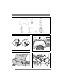
2.1 Accessories bag
The machine is supplied with a plastic bag contain-
ing components which shall be used during the as-
sembly. The bag contains (fig. 1):
Pos. No. Designation Dimension
A 1 Drawing plate
B 2 Screw 8 x 20
C2 Nut M8
D 1 Tension pin 6 x 36
E 1 Shim washer 16 x 38 x 0.5
F 1 Shim washer 16 x 38 x 1.0
G 2 Shoulder washer
H 2 Screw 8 x 20
I 2 Knob
J 4 Washer 8.4 x 22 x 1.5
K 2 Screw, Comfort, President,
Excellentonly
L 2 Ignition key
2.2 Engine casing
To inspect and maintain the engine and battery, re-
move the engine casing. Dismantling:
1. Unscrew the fuel cap/fuel gauge.
2. Pull up the rubber strap at the front edge of the
casing (fig. 2).
3. Carefully lift off the engine casing (fig. 3).
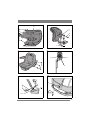
Assembly:
1. Place the casing over the lip on each side.
2. Make sure that the pins on the rear edge of the
casing go down into the respective holes (fig. 4).
3. Secure the front edge of the casing with the rub-
ber strap (fig. 2).
4. Finally, screw in the fuel cap/fuel gauge.
The machine may not be operated un-
less the engine casing is closed and
locked. Risk of burns and crushing in-
juries.
2.3 Battery
Do not short circuit the battery’s termi-
nals. Sparks occur which can result in
fire. Do not wear metal jewellery which
can come into contact with the battery
terminals.
In the event of damage to the battery
casing, cover, terminals or damage to
the strip covering the valves, the bat-
tery should be replaced.
The battery is a valve-regulated battery with 12 V
nominal voltage. The battery fluid does not need to
and cannot be checked or topped up. The only
maintenance that is required is charging, for exam-
ple after extended storage.
After charging the battery must be stored in a cool
place.
The battery must be fully charged be-
fore being used for the first time. The
battery must always be stored fully
charged. If the battery is stored while
discharged, serious damage will occur.
2.3.1 Charging with the engine
The battery can be charged using the engine’s gen-
erator as follows:
1. Install the battery in the machine as shown be-
low.
2. Place the machine outdoors or install an extrac-
tion device for the exhaust fumes.
3. Start the engine according to the instructions in
the user guide.
4. Allow the engine to run continuously for 45
minutes.
5. Stop the engine. The battery will now be fully
charged.
2.3.2 Charging using battery charger
When charging using a battery charger, a battery
charger with constant voltage must be used.
Contact your dealer to purchase a battery charger
with constant voltage.
The battery can be damaged if a standard type bat-
tery charger is used.
2.3.3 Installing the battery
1. Open the engine casing and position the battery
in the appropriate place. See fig. 5.
2. Secure the battery in position.
3. First connect the red cable to the battery’s posi-
tive terminal (+).
4. Connect the black cable to the battery’s
negative terminal (-).

16
ENGLISH
EN
If the cables are interchanged, the gen-
erator and the battery will be damaged.
The engine must never be driven with
the battery disconnected. There is a risk
of serious damage to the generator and
the electrical system.
2.4 Seat switch
(Comfort, President, Excellent)
See fig. 6. At the underside of the seat is a switch,
which plays an important role in the machine’s
safety system located.
Assemble the switch as follows:
1. Loosen the switch from the cables.
2. Assemble the switch at the underside of the seat
with the screws (K).
3. Reconnect the cables to optional pins at the
switch.
2.5 Seat
See fig. 7. Install the mounting in the rear (upper)
holes as follows:
1. Install the shoulder washers (G) on the screws
(H).
2. Insert the screws through the slots in the brack-
et. Place a washer (J) between the seat and the
bracket.
3. Tighten the screws in the seat. Tightening
torque: 9±1.7 Nm.
If the screws are tightened more than
9±1.7 Nm, the seat will be damaged.
4. Check that the seat moves easily in the slots in
the bracket.
Install the mounting in the front (lower) holes as
follows:
1. Install a washer (J) on each knob (I).
2. Insert the knobs through the slots in the bracket
and tighten by hand in the seat.
3. Fold the seat down and place it in the desired
position.
4. Tighten the screw knobs (I) by hand.
The screw knobs (I) and the seat will be
damaged if tools are used.
The seat can be folded. If the machine is parked
outside when it is raining, fold the seat forward to
protect the seat cushion from getting wet.
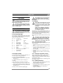
2.6 Arm rests (Pro20)
See fig. 8, 9. The arm rests and the installation
components are supplied in a separate box. Assem-
ble as follows:
1. Assemble the left and right mounts onto the
seat. Use 3 screws (Q) supplied at each side.
2. Assemble the arm rests with screws (R), nuts
(S) and spacers (T).
3. Tighten the screws so that the arm rests simply
can be folded up/down.
2.7 Steering wheel
See fig. 10. In order to minimise the axial play in
the steering column, the shim washers (E) and/or
(F) must be installed on the steering column be-
tween the steering column jacket and the bracket
as follows.
1. Install the steering column jacket on the steer-
ing column and secure by knocking in the ten-
sion pin (D) approximately 1/3 of its length.
2. Pull the steering column jacket and the steering
column up.
3. From the outside, check whether no washers,
the 0.5 mm washer, the 1.0 mm washer or both
washers can be inserted into the gap. The wash-
er/washers must not be forced in, as there must
be a little axial play.
4. Pull out the cotter pin and dismantle the steering
wheel jacket.
5. Install the washer/washers in accordance with
point 3 above.
6. Install the steering column jacket on the steer-
ing column and secure by knocking in the ten-
sion pin fully. Use a counterhold.
2.8 Towing hitch
See fig. 11. Screw the towing hitch (A) into the two
holes on the underside of the rear axle using screws
(B+C). Tighten the screws properly.
Tightening torque: 22 Nm.
2.9 Tyre pressure
Check the air pressure in the tyres. Correct air
pressure:
Front: 0.6 bar (9 psi)
Rear: 0.4 bar (6 psi)
2.10Accessories
For the installation of accessories, see separate in-
stallation guide supplied with each accessory.
Note: The cutting deck is regarded as an accessory
here.

www.stiga.com
GGP Sweden AB
·
Box 1006
·
SE-573 28 TRANÅS
-
 1
1
-
 2
2
-
 3
3
-
 4
4
-
 5
5
-
 6
6


Ask a question and I''ll find the answer in the document
Finding information in a document is now easier with AI
Related papers
-
Stiga GARDEN 8211-0202-11 User manual
-
-
-
-
-
-
-
-
-
Other documents
-
Castelgarden XK 140 HD Installation guide
-
Mountfield 4135H User manual
-
TVS Apache RTR 200 4V User manual
-
 Dong Feng ZB25 User manual
-
Datsun Saloon I300 Workshop Manual
-
Terex TR60 Maintenance Manual
-
Fiat TIPO 4DOORS Owner's manual
-
 Hafei SIGMA Service User manual
-
-
SKODA Fabia (2015/11) Owner's manual

