State Industries STC-080 User manual
- Category
- Water heaters & boilers
- Type
- User manual

SERVICE HANDBOOK
FOR
STANDARD RESIDENTIAL
GAS WATER HEATERS
(NON POWER VENTED MODELS)
Printed in the USA 0604 Part Number STC-080
$15.00
This service handbook addresses service issues associated with Standard Residential Gas
Water Heaters. Includes C-3 Flammable Vapor Technology.

RESIDENTIAL GAS, NON POWER VENTED, WATER HEATER
SERVICE HANDBOOK
State Water Heater Technical Training Department
© 2004 Ashland city, TN
1
TABLE OF CONTENTS
Page
Introduction
Terms.........................................................1
Tools..........................................................2
Residential Gas Water Heaters
Guidelines..................................................3
Installation..................................................5
Operations and Servicing
Construction...............................................6
Control.......................................................6
Burner........................................................7
Normal Operations ....................................7
Temperature..............................................8
Gas............................................................8
Water Flow.................................................9
Page
Service.....................................................10
Procedures and Conditions .....................11
Multiple Heater Piping..............................14
Exhaust Venting Notes ............................15
Flammable Vapor Ignition Design …….15
Lint, Dust & Oil Screen…………………16
Flame Arrestor…………………………..17
Thermal Cut Off Switch………………...18
Pilot Burner Assembly………………….19
Sealed Combustion Chamber…………20
Piezo Igniter……………………………..21
Technical Bulletins ……………….. 26
RESIDENTIAL GAS SERVICE HANDBOOK INTRODUCTION
This service handbook is designed to aid in servicing and troubleshooting State Non
Power Vented, Residential Gas water heaters in the field. No duplication or reproduction of this
book may be made without the express written authorization of the manufacturer.
The following text and illustrations will provide you with a step-by-step procedure to
verify proper installation, operation, and troubleshooting procedures. Additional quick reference
data is included to assist you in servicing this product.
The information contained in this handbook is designed to answer commonly faced
situations encountered in the operation of the Residential Gas, non power vented, product line
and is not meant to be all-inclusive. If you are experiencing a problem not covered in this
handbook, please contact the State Water Heater Call Center at 1-800-365-0024 or your local
State Water Heater Service Representative for further assistance. Additional information is also
available on the web site www.Statewaterheaters.com
. This handbook contains supplemental
information to the Residential Gas installation instructional manual supplied with the water
heater.
Qualifications
This handbook is intended for use by licensed plumbing professionals and reference should be
made to the instructional manual accompanying the product.

RESIDENTIAL GAS, NON POWER VENTED, WATER HEATER
SERVICE HANDBOOK
State Water Heater Technical Training Department
© 2004 Ashland city, TN
2
Tools Required:
Phillips head screw driver
3/8, 7/16, ¾ inch open end wrenches
3/16 inch Allen wrench
11/16 inch – 6 point – socket – for anode removal
set of marked drill bits
electrical multimeter
gas pressure gauge or monometer
water pressure gauge
thermometer
tubing cutter if pilot tube is to be replaced
hose – to drain tank
container – to measure gallons per minute flow
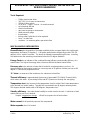
MISCELLANEOUS INFORMATION
Draw efficiency is the quantity of hot water available to the consumer before the outlet water
temperature decreases 25 degrees F. A 40 gallon water heater will typically provide 70% (28
gallons) of this “usable” hot water. The burner is allowed to operate during this test. Incoming,
cold water mixes the remaining stored water below this 25 degree limitation.
Energy Factor is an indicator of the combined thermal efficiency and standby efficiency of a
water heater. The higher the energy factor, the more efficient the water heater will be.
Recovery rate is the amount of water that is heated to a set temperature, per hour. An
example might be that a water heater has a recovery rate of 30 gallons of water per hour at 80
degree F. (Fahrenheit) temperature rise.
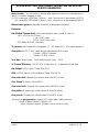
“R” Value is a measure of the resistance of a substance to heat flow.
Thermal efficiency is approximately the amount of generated BTU (British Thermal Units),
which enters the water. A percentage of the total BTU passes out through the vent piping.
Temperature rise is the increase in the temperature from its coldest “inlet” water temperature
to the desired hot (outlet) setting. Typically this is assumed to be 40 degrees entering water;
120 degrees desired stored water or 80 degrees “temperature rise.”
Standby efficiency – the water heater’s ability to contain heat in the tank. A minimum of tank
water heat loss per hour is desired.
Sample: temperature change
= Btu/h loss/ square foot of tank surface
“R” value
Water cannot
(for all practical purposes) be compressed.
Water expands when it is heated.

RESIDENTIAL GAS, NON POWER VENTED, WATER HEATER
SERVICE HANDBOOK
State Water Heater Technical Training Department
© 2004 Ashland city, TN
3
Water Hammer – is a concussion of moving water against the sides of a containing pipe or
vessel on a sudden stoppage of flow.
EX: 1/2 “copper pipe, 5GPM flow (7.2ft/sec.) – stop. Pressure rise of approximately 412 PSI.
3/4” copper pipe, 5GPM flow (3.3ft/sec) – stop. Pressure rise of approximately 188 PSI
Minerals and gases will separate from water as temperature increases.
Formulas:
Btu (British Thermal Unit) is the heat required to raise 1 pound of water 1F
1 BTU = 252 cal = 0.252 kcal
1 cal = 4.187 Joules
BTU X 1.055 = Kilo Joules
BTU divided by 3,413 = Kilowatts
To convert from Fahrenheit to Centigrade: (° F – 32) times 5/9, or .556, equals degrees C.
One gallon of (120 F, 49C) water weighs approximately 8.25 pounds.
Pounds X .45359 = Kilogram
Gallons X 3.7854 = Liters
% of Hot = (Mixed Temp. – Cold) divided by (Hot Temp. – Cold)
% Thermal Efficiency = (GPH X 8.25 X Temp. Rise X 1.0) divided by BTU/H Input
Btu Output = GPH X 8.25 X Temp. Rise X 1.0
GPH = (BTU/H Input X % Eff.) divided by (Temp. Rise X 8.25)
One cubic foot of Natural Gas contains about 1000 BTU of heat.
One “therm” is equal to 100,000 BTU
One cubic foot of Propane Gas contains about 2500 BTU of heat.
One gallon of Propane gas contains about 91,250 BTU of heat.
One pound
of Propane gas contains about 21,600 BTU of heat.
One pound of gas pressure is equal to 27.7 inches water column pressure
Inches of Water Column X .036091 = PSI
Inches of Water Column X .073483 = Inches of Mercury (Hg.)

RESIDENTIAL GAS, NON POWER VENTED, WATER HEATER
SERVICE HANDBOOK
State Water Heater Technical Training Department
© 2004 Ashland city, TN
4
Centimeters = Inches X 2.54
MM (millimeters) = Inches X 25.4
Meters
= Inches X .0254
Doubling the diameter of a pipe will increase its flow capacity (approximately) 5.3 times.
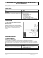
CONSTRUCTION:
Tank is constructed of steel.
The inside of the tank is constructed of a
glass lining bonded to the steel. This prevents
water to metal contact and rusting of the tank.
An
anode rod will be installed within the tank. The hex-head plug end of the anode is visible
on the top of the water heater. This metal rod offers secondary protection of the tank against
corrosion where the application of glass is not possible (threaded tank openings). These areas
will have small areas of water to metal contact.
All water heaters will contain at least
one thermostat (to operate the heater) and one high
limit (to prevent water temperatures approaching the “steam” level).

RESIDENTIAL GAS, NON POWER VENTED, WATER HEATER
SERVICE HANDBOOK
State Water Heater Technical Training Department
© 2004 Ashland city, TN
5
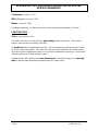
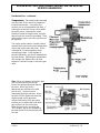
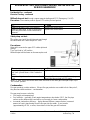
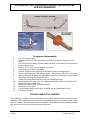
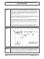
INSTALLATION OF RESIDENTIAL GAS WATER HEATER
Exhaust Vent to
Outside of Building
Union
See Manual and
Labels For Installation
Clearances
Temperature And
Pressure Relief
Valve – Do Not
Reuse Old Valve.
Expansion Tank
Pressurize to Equal
Supply Water
Pressure
Water
Shut Off
V
alve
Temperature and
pressure relief valve
tube piped to within 6”
of drain.
Thermostat –
recommended starting
point - 120F.
Safety Pan – Piped to
Drain
Drain
Inner and
Outer Doors –
Reinstall After
Lighting Pilot.
Air Is Drawn In For
Combustion. Keep
area clean and free
from flammables and
flammable vapors
Maximum Gas Supply
13.8” W.C. or ½ PSI
Minimum
4.5” W.C. –Natural Gas
11.0” W.C. Propane Gas
Installation Must Follow Local Codes and Instruction Manual Guidelines
Union
Typical Model
and Rating
Plate Location

RESIDENTIAL GAS, NON POWER VENTED, WATER HEATER
SERVICE HANDBOOK
State Water Heater Technical Training Department
© 2004 Ashland city, TN
6
RESIDENTAL GAS WATER HEATER SERVICE
This portion of this manual applies to the Operations and Servicing of Residential Gas, Tank
Type, Water Heaters, which are vented atmospherically and use a thermocouple as their
electrical source.
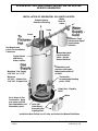
Control: There is one control on this style of water heater. The control has a main gas
regulator, pilot gas regulator, on-off-pilot knob, controls water temperature, has a temperature
adjustment knob, and a high water temperature limit safety.
(delta)
Note: The word “Hot”
may or may not be
present on the control
knob

RESIDENTIAL GAS, NON POWER VENTED, WATER HEATER
SERVICE HANDBOOK
State Water Heater Technical Training Department
© 2004 Ashland city, TN
7
Residential Gas – continued
Burner: The burner assembly consists of the main burner, main burner orifice, main burner
gas supply tube, pilot burner, pilot burner orifice, pilot burner gas supply tube and thermocouple.
The pilot burner remains on once it is manually lit. When incoming cold water activates the
thermostat, gas flows to the main burner. The pilot flame ignites this gas. The main flame
burns until the tank reaches set temperature then the thermostat interrupts this main gas flow.
AFTER HAVING CONFIRMED THAT THE WATER HEATER HAS BEEN INSTALLED
PER THE INSTALLATION MANUAL INSTRUCTIONS:
Normal Operation
Electrical: The Pilot Flame heats the end of a thermocouple. As the thermocouple is heated,
it generates a small (cannot be detected without an electrical meter) electrical current to the
bottom of the control valve. This current powers the electromagnet and holds open the safety
valve as long as the pilot flame is heating the thermocouple. DANGER! If the pilot is
extinguished, it can take up to 180 seconds for the thermocouple to cool sufficiently to close the
safety valve.
See also C3 technology product information beginning on page 15 .

RESIDENTIAL GAS, NON POWER VENTED, WATER HEATER
SERVICE HANDBOOK
State Water Heater Technical Training Department
© 2004 Ashland city, TN
8
Residential Gas – continued
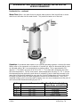
Temperature: Two metal probes mounted
onto the back of the control are immersed
inside the tank water. One probe (the
shorter) acts as a temperature high limit. If
water gets excessively hot, a sensor within
the probe opens, interrupts the small
electrical current to the gas valve, and gas
flow through the control is interrupted. If this
safety sensor opens, the entire control must
be replaced.
The longer probe contains a metal rod that
expands and contracts as water temperature
around the probe cools and heats. As the
rod expands, it pushes against a lever
actuated gas valve. If the regulator is
pushed sufficiently, gas flow is interrupted to
the main burner. Adjusting the temperature
dial changes the distance the rod must
expand or contract to open or close the gas
valve.
Gas: When you prepare to light the pilot,
you are instructed to turn the top
knob to the pilot position and depress
the knob. When the knob is
depressed gas will flow to the pilot
burner only. You then have to
(manually) ignite this pilot gas. When
the pilot is lit, the flame must heat the
thermocouple until it generates
sufficient electricity to the gas valve
to allow you to release the knob while
gas continues to flow to the pilot.
When the top knob is turned to the
“ON” position, gas is also available to
the main burner if the thermostat calls
for heat.

RESIDENTIAL GAS, NON POWER VENTED, WATER HEATER
SERVICE HANDBOOK
State Water Heater Technical Training Department
© 2004 Ashland city, TN
9
Residential Gas - continued
Water Flow: When a hot water faucet is opened, water pressure from the well tank or street
main forces cold water into the water heater. This pushes hot water out of the tank.
Operation: A residential water heater is not a precise operating appliance. Because the water
heater relies on the expansion and contraction of a metal rod, when the thermostat dial is set at
an indicated setting (“▲” is recommended as a starting setting. This is approximately 120
degrees F.) The heater may shut off at 110 to 130 F. The heater will consistently shut off at
this same temperature. For this same reason, water temperature may drop 15 - 25 F, around
the temperature probe, before the main burner is activated. Keep in mind that hot water in the
upper part of the tank will probably be very near the “shut off” temperature of the control while
incoming cold water drops the water temperature around the thermostat probe. Also, short
repeating heating cycles caused by small hot water uses can cause temperatures at the point of
use to exceed the thermostat setting by up to 30° F.
Setting Approximate Temperature (°F) Time To Produce 2
nd
& 3
rd
Degree Burns on Adult Skin
Hot (▲)
120° ± 10° 5 Minutes
A 130° ± 10° 30 Seconds
B 140° ± 10° 5 Seconds
C 150° ± 10° 1.5 Seconds
Very Hot 160° ± 10° Under 1 Second

RESIDENTIAL GAS, NON POWER VENTED, WATER HEATER
SERVICE HANDBOOK
State Water Heater Technical Training Department
© 2004 Ashland city, TN
10
Residential Gas - continued
Service:
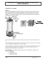
Air:
A gas burning appliance requires the oxygen contained in 12.5 cubic feet of air (at sea
level) for every 1000 BTU of heat that is generated. If your water heater has a BTU per hour
input of 40,000 BTU then a minimum of 500 (40 times 12.5) cubic feet of clean air must be
available. This oxygen will mix with the gas for a clean, blue flame in the burner chamber and
provide dilution air for flue products.
Do not forget that your gas (or oil) furnace and gas clothes dryer also require a like amount of
air.
When calculating air supply provisions, also consider the presence of whole house exhaust fans
or other exhaust fans competing for the same air supply.
Air must be allowed to enter the heater chamber from the base of the heater and also enter the
flue vent from below the draft hood. Do not block these areas with insulation blankets or
obstructions lying around the base of the heater.
Lack of Oxygen: If a sufficient supply of oxygen (air) is not available for combustion and
dilution, the result will be:
Pilot outage
Yellow burner flame
Sooting water heater
12.5
Cubic
Feet of
Air
+=
1,000
BTU
Fuel
(Enters
Here)
(Enters Here)

RESIDENTIAL GAS, NON POWER VENTED, WATER HEATER
SERVICE HANDBOOK
State Water Heater Technical Training Department
© 2004 Ashland city, TN
11
Possible carbon monoxide
Smell of burnt gas in the room
Residential Gas – continued
The instruction manual gives guidelines under “Air Requirements” and “Unconfined “ or
“Confined Space” sections. If you want to test for a lack of air:
1. Turn on every appliance and fan that exhausts air from the utility room and/or house.
Make sure all windows and doors are closed, as well as chimney dampers.
2. Open a hot water faucet so that the main burner will ignite
3. Remove the outer door of the water heater – not the inner door
4. Monitor the flame characteristics for several minutes
If the flame begins to “yellow” open a door or window, to the outdoors, to see if additional air
corrects this back to blue. If it does, the room needs more air supply. Perform draft test at draft
hood of water heater with match or smoke source to verify.
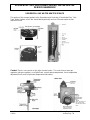
Manifold
Gas Pressure
Test
Gas pressure checks are done with flowing gas.
Supply gas pressure checks are taken ahead of the gas control and as close to the heater
as possible.
Pilot gas pressure checks are taken by using fitting adapters to tap into the pilot gas tubing.
Manifold (main burner) gas pressure is measured using the Allen wrench tap on the
bottom of the control valve.
Desired gas pressures will be noted on the gas valve label.
If … … then
supply gas pressure is under desired pressure
setting
increase supply gas pressure regulator
setting and,
increase supply gas piping size.
supply gas pressure is over desired pressure
add gas pressure regulator.
reduce setting on existing regulator.
pilot gas pressure is more than +/- .3 inch
W.C. from desired
replace the control valve.
manifold gas pressure is more than +/- .3 inch
W.C. from desired
replace the control valve.
Additional considerations when pilot or main burner flames are too large or too small:
Incorrect orifice
Dirt in orifice or gas supply tubing
Testing with
Gas
Pressure
Gauge
Pilot Gas
Pressure
Test

RESIDENTIAL GAS, NON POWER VENTED, WATER HEATER
SERVICE HANDBOOK
State Water Heater Technical Training Department
© 2004 Ashland city, TN
12
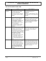
Residential Gas - continued
Sooting causes:
If … … then
the burner is clean but the chamber and/or flue
are sooted
check for lack of supply air.
the main burner, chamber and flue are sooted check the following:
incorrect orifice
excessive gas pressure
loose main burner
cross threaded orifice
gas control valve gas seepage
loose gas connection in burner assembly.
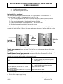
Electrical Testing
This type of water heater has its own electrical
generating system.
When two dissimilar metals are joined together
and this joint is heated, a small, electrical current
will be produced. A thermocouple uses this
science.
Thermocouple output test
Procedures/Conditions:
Meter set for DC millivolt testing
Test from lower ECO (emergency cut off or energy cut off) solder joint to ground.
Note: If pilot will not stay lit, manually hold the top knob down in the pilot position. This allows
gas to flow to the pilot. Light the pilot and continue to hold this knob down while conducting the
test.
If … … then
reading test of at least 13 mV is not present check that flame contacts end of
thermocouple
replace thermocouple.
reading test of at least 13 mV is present continue to next test.
TO GROUND

RESIDENTIAL GAS, NON POWER VENTED, WATER HEATER
SERVICE HANDBOOK
State Water Heater Technical Training Department
© 2004 Ashland city, TN
13
Residential Gas - continued
Electrical Testing– continued
Millivolt dropout test through copper magnet winding and ECO (Emergency Cut Off)
Procedure: Move meter probe to upper ECO solder joint and ground
If … … then
reading of at least 10 mV is not present replace the control valve.
reading of more than 10 mV is present but,
gas to the pilot shuts off each time knob is
released
replace the control valve.
Safety drop out test –
The safety gas shutoff should interrupt gas through
the valve when mV current drops to 1-3 mV.
Procedures:
Meter still connected to upper ECO solder joint and
ground.
Turn Top Knob to “off” position
Millivolt output will decrease as thermocouple cools
If… … then
internal safety does not activate between 1
and 3 mV (you will hear a “click” inside the
valve)
replace the control valve.
*internal safety does activate between 1 and
3 mV
valve is within tolerance and will interrupt gas
flow if pilot looses heat or ECO opens.
*Note: A “click” sound should be heard from the valve as the main gas interrupter snaps up to
the “closed” position.
Condensation
Flue gas products contain moisture. If these flue gas products are cooled to their “dew point”,
they become visible moisture – condensation.
Flue gas may become cooled by:
Cold supply air temperatures
Cool surfaces – generally, if tank water temperatures drop below 110F, the flue pipe
surface and/or bottom tank head will be cool enough to cause condensation.
Increased combustion efficiency – higher thermal efficiency means that an increased
amount of heat is transferring from the flue gas into the water. If you transfer
(approximately) 87.5%, or more, the moisture in the flue gas will condense.
TO GROUND

RESIDENTIAL GAS, NON POWER VENTED, WATER HEATER
SERVICE HANDBOOK
State Water Heater Technical Training Department
© 2004 Ashland city, TN
14
Residential Gas – continued
Condensation is a mild acid – it will corrode steel
Condensation is usually noted when:
water dripping is heard (only) while the main burner is on,
there is “water” around the heater just after the heater has been operating,
there are small, black or red granules on the main burner or top of the heater or
corroded jacket or vent piping is noted.
If … … then
any of the above conditions exist raise the supply air temperature or
increase stored water temperature or
increase the size of the tank
You would not wish to lower combustion
efficiency – this would waste gas. Use
materials (stainless steel, PVC etc.) that
will not be affected by the condensation
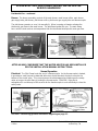
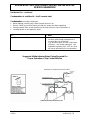
Suggested Multiple Heater Water Piping Required For
Proper Operation of Top Connect Models
Installed in accordance with local codes.
TEMPERATURE/PRESSURE RELIEF VALVES

RESIDENTIAL GAS, NON POWER VENTED, WATER HEATER
SERVICE HANDBOOK
State Water Heater Technical Training Department
© 2004 Ashland city, TN
15
Residential Gas – continued
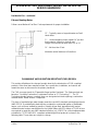
Exhaust Venting Notes
Follow current National Fuel Gas Code requirements for proper installation.
“D” – Typically, same or larger diameter as Draft
Hood outlet
“L” – Horizontal piping slopes upward ¼” per foot
from heater to chimney or vertical vent
Length of horizontal not more than 75% of “H”
“H” – Not less than 5 feet
Maximize vertical distance to first elbow
FLAMMABLE VAPOR IGNITION RESISTANT (FVIR) DESIGN
This section will address the changes brought about by the introduction of FVIR compliant
products. Other than items mentioned here, the construction, installation, and service will
remain the same as discussed in the primary handbook.
The FVIR acronym stands for "Flammable Vapor Ignition Resistant." The State products are
based on "Corderite Combustion Containment" known as “C3 Technology™” . The C3
Technology design features a sealed (from non designated air intake openings) combustion
chamber and a "flame arrestor" component.
This class of residential gas water heaters meet the new ANSI standards and testing protocols
(ANSI Z21.10.1) established to deal with the accidental or unintended ignition of flammable
vapors, such as those emitted by gasoline. Virtually all gas-fired, atmospherically vented,
residential water heaters manufactured in the United States with BTU ratings of 75,000 or less
are required to meet this new ANSI standard effective July 1,2003. The current implementation
schedule for C3 TECHNOLOGY compliant residential gas-fired products is shown in the
following table. These dates are subject to change.

RESIDENTIAL GAS, NON POWER VENTED, WATER HEATER
SERVICE HANDBOOK
State Water Heater Technical Training Department
© 2004 Ashland city, TN
16
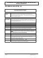
IMPLEMENTATION
CATEGORY
ANTICIPATED
INTRODUCTION
CLASS OF PRODUCTS
INCLUDED IN THIS CATEGORY
Phase I
July 1, 2003
(July 1, 2004* Can.)
30, 40, and 50 gallon atmospheric vented.
(Manufactured housing models are excluded.)
Phase II January 1, 2005*
30, 40, and 50 gallon power-vented models.
(Manufactured housing models are excluded.)
Phase III July 1, 2005*
All other gas-fired models with inputs of 75,000 BTU
or less.
* Subject to change. This supplement addresses the July1, 2003 compliant products.
In addition to the standard water heater design discussed in the main service handbook, the C3
Technology design also includes:
A LDO (Lint Dust and Oil) screen over the combustion air intake
A Flame Arrestor
A combustion chamber Thermal Cut Off (TCO) limit
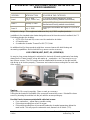
An additional tool for these products might be a vacuum cleaner with both blowing and
vacuuming capabilities. Also include the long, narrow crevice accessory.
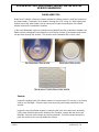
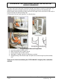
LDO SCREEN (LINT, DUST, OIL) SCREEN(S)
An easy to clean screen designed to minimize lint, dust and oil based contaminants from being
drawn into the “Flame Arrestor” along with make up – combustion - air. There may be one or
two of these screens. The LDO screen must be installed with the arrows on the right and left
side facing up to function properly. (The arrows are located on two mounting tabs on each side
of the screen).
Service:
Inspect the LDO screen(s) regularly. Clean or wash as necessary.
Pulling the tab located in the middle of the screen will remove the screen. Reinstall the clean
screen by inserting the end tabs into the jack with the arrows pointing up.
Possible Service issues associated with a blocked screen:
Poor combustion – yellow flame, possible sooting
Pilot outage resulting from a lack of oxygen
Pilot outage resulting from to increased combustion chamber temperature below the
main burner. This may open the automatic reset, thermal cut off switch (TCO).

RESIDENTIAL GAS, NON POWER VENTED, WATER HEATER
SERVICE HANDBOOK
State Water Heater Technical Training Department
© 2004 Ashland city, TN
17
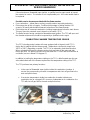
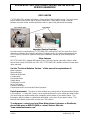
FLAME ARRESTOR
Made from Corderite, a fireproof ceramic material, the flame arrestor is built into the base of
the water heater. Combustion air is drawn in through the LDO screen (s). After entering the
bottom area of the water heater, this air passes up through the small ports of the flame
arrestor and into the combustion chamber.
In the event flammable vapors are introduced accidentally into the combustion chamber, the
flame arrestor is designed so any flames burn off the top surface of the arrestor and cannot
escape down through the arrestor. The arrestor works somewhat like a check valve.
Service:
Inspect the bottom ports of the flame arrestor by removing the LDO screen (s) and using
a mirror and flashlight. Clean the ports if necessary by vacuuming the bottom of the
arrestor.
Inspect the top of the flame arrestor by removing the inner door and burner assembly.
Lift the heat shield located on the bottom of the chamber. Inspect with the mirror and
flashlight. Vacuum or blow down any blocking material. If you blow down through the
ports, be certain to also vacuum below the arrestor.

RESIDENTIAL GAS, NON POWER VENTED, WATER HEATER
SERVICE HANDBOOK
State Water Heater Technical Training Department
© 2004 Ashland city, TN
18
If there has been a flammable vapor ignition, a qualified service agent needs to inspect
the arrestor for cracks. The arrestor is not a replaceable part – the heater would need to
be replaced.
Possible service issues associated with the flame arrestor.
Poor combustion – yellow flame, sooting, possible carbon monoxide production.
Pilot outage due to lack of oxygen. Continued pilot outage or finding that the LDO
screen(s) is heavily blocked would warrant inspection of the flame arrestor.
Pilot outage due to increased combustion chamber temperatures below the main burner.
This may open the automatic reset, thermal cut off switch (TCO).
The flame arrestor having contained a flammable vapor ignition. The TCO will open and
the chamber and arrestor should be inspected by a qualified service agent.
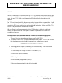
COMBUSTION CHAMBER TEMPERATURE SENSOR
The C3 Technology water heaters will come equipped with a thermal cutoff (TCO)
device that is integral with the thermocouple. Temperature cutoff points range from
160°C to 200°C depending on model. The TCO is an automatic reset thermal switch.
When activated it will open the thermocouple circuit and shut off the main and pilot
burner gas flow. The pilot would have to be relit after the TCO has had sufficient time to
cool down (sensor is below 120 degrees F).
In addition to printing the temperature setting on the TCO, a label located near the gas
valve attachment end of the thermocouple notes the temperature setting of the TCO.
The TCO performs two primary functions:
In the event of flammable vapor ignition inside the combustion chamber, it
senses the corresponding increase in temperature and shuts off gas flow to the
main and pilot burners.
If excessive temperatures inside the combustion chamber indicate poor
combustion due to a clogged LDO screen or inadequate air for combustion, the
TCO will shut off gas flow to the main and pilot burners.

RESIDENTIAL GAS, NON POWER VENTED, WATER HEATER
SERVICE HANDBOOK
State Water Heater Technical Training Department
© 2004 Ashland city, TN
19
SERVICE:
There is no routine service associated with the TCO. The standard thermocouple millivolt output
checks described in this service handbook still apply. Millivolt readings indicate that the TCO is
closed. An open TCO (within a cool chamber) would indicate that the assembly must be
replaced.
The TCO is an integral part of the thermocouple and not replaceable as a separate item. A pilot
burner assembly must be reinstalled. On repeated calls of no hot water or pilot outage, a
clogged/dirty LDO screen might be the cause and should be checked. Keep in mind this TCO
will shut off the pilot and main burner when activated.
With the different cutoff temperature set-points of TCO devices for different model water
heaters, it is important that the correct part is used when replacement of the pilot burner
assembly is necessary.
Possible service issues associated with the Thermal Cut Off switch being opened:
Pilot outage due to increased combustion chamber temperatures below the main burner.
This may open the automatic reset, thermal cut off switch (TCO).
The flame arrestor having contained a flammable vapor ignition. The TCO will open and
the chamber and arrestor should be inspected by a qualified service agent.
ONE PIECE PILOT BURNER ASSEMBLY
C3 Technology models feature a "one piece" pilot burner assembly. There are five main
components that make up this pilot assembly:
1. Thermocouple with integral Thermal Cut Off switch (TCO).
2. Pilot burner w/orifice and tubing
3. Piezo igniter cable
4. Pilot assembly seal/grommet (orange).
5. An inner door gasket (white) will also be included.
Page is loading ...
Page is loading ...
Page is loading ...
Page is loading ...
Page is loading ...
Page is loading ...
Page is loading ...
Page is loading ...
Page is loading ...
Page is loading ...
Page is loading ...
Page is loading ...
Page is loading ...
Page is loading ...
Page is loading ...
Page is loading ...
-
 1
1
-
 2
2
-
 3
3
-
 4
4
-
 5
5
-
 6
6
-
 7
7
-
 8
8
-
 9
9
-
 10
10
-
 11
11
-
 12
12
-
 13
13
-
 14
14
-
 15
15
-
 16
16
-
 17
17
-
 18
18
-
 19
19
-
 20
20
-
 21
21
-
 22
22
-
 23
23
-
 24
24
-
 25
25
-
 26
26
-
 27
27
-
 28
28
-
 29
29
-
 30
30
-
 31
31
-
 32
32
-
 33
33
-
 34
34
-
 35
35
-
 36
36


State Industries STC-080 User manual
- Category
- Water heaters & boilers
- Type
- User manual
Ask a question and I''ll find the answer in the document
Finding information in a document is now easier with AI
Related papers
-
State Industries SBD71 User manual
-
-
-
-
State 186489-002 User manual
-
-
-
State Water Heaters SUF-130-300 User manual
-
-
Other documents
-
BENDIX TCH-006-001 User manual
-
-
Fluke 28 II Ex Intrinsically Safe True RMS Digital Multimeter User manual
-
Rheem INTELLI-VENT Troubleshooting guide
-
-
A.O. Smith 200 Series Service Handbook
-
 Reliant 200 Series Datasheet
-
-
-
PVI Industries PV 6127b User manual
