Page is loading ...

P
C
X
-
U
3
0
2
P
C
X
-
U
3
0
2
PLL True
diversity
UHF
wireless
receiver
PLL True
diversity
UHF
wireless
receiver
OPERATING GUIDE

INTRODUCTION
Thank you for selecting a Peavey Pro Comm PCX-
U302 quartz controlled single channel true diversity wireless
microphone system. Before operating and installing this
system please read this instruction manual carefully and
thoroughly in order to attain the correct operating
procedures and to achieve the best results.
True Diversity Receiver
The Peavey Pro Comm PCX-U302 quartz controlled
receiver is a true diversity wireless system. This system is
also equipped with “Superior frequency tracking and muting
techniques” that is effective in eliminating the random noise
interference when the receiver is in standby state. The
Peavey Pro Comm PCX-U302 receiver is equipped with
both balanced and unbalanced outputs.
This system includes the following accessories:
• AC/DC Adapter
• Mic Clip
• Antenna (2)
• Instruction Manual
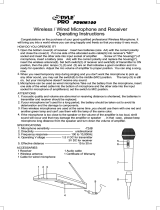
1. UNIT FEATURES AND FUNCTIONS
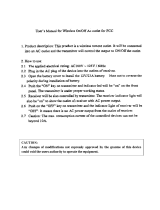
A. Front Panel
Figure 1
1
2
7 8 109
3
5
4
3
6

1. Antenna Input Connector A
2. Power Switch and Indicator:
When the switch is turned on the red indicator
illuminates to denote normal power status.
3. Group Selector:
Selects a group of frequencies.
4. Channel Selector:
Selects a channel within a group. There are six
group numbers available. Groups one through four
each have six available channels (one through six).
Groups five through six each have three available
channels (one through three). All channels within the
same group are non-interfering when used in multiple
system installations (except group six).
5. Group Indicator:
Indicates the group selected.
6. Channel Indicator:
Indicates the channel selected.
7. RF Signal Level Indicator:
Indicates the RF signal strength received from the
microphone. As soon as the signal is emitted from
the microphone the LED indicator illuminates.
8. Audio Signal Level Indicator:
Indicates the audio signal level. As soon as the
microphone signal is modulated, the LED indicator
illuminates.
9. Volume Control:
Adjusts the AF output level of the receiver.
4

10. Antenna Input Connector B
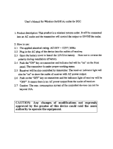
REAR PANEL
B. Rear Panel
11. DC 12V Input Jack:
Connect the 12V DC plug from the AC/DC adapter.
12. Balanced Audio Output Jack:
XLR type connector
13. Unbalanced Audio Output Jack:
1/4" Phone Jack
14. Unbalanced Level Switch:
“LOW” selection is for “Microphone-Level” output.
“HIGH” selection is for “Line-Out” level output.
15. Squelch Adjustment:
Adjust the squelch level to eliminate the RF noise
interference at the receiver.
2. INSTALLATION OF THE RECEIVER
1. Install one of the antennas at the antenna
input connector A. Then install the other
antenna at the antenna input connector B.
Make sure both antennas are in the vertical
position.
Figure 2
5
11
12 13 14 15

2. AC/DC Power Connection:
Fig. 3
Connect the AC/DC adapter cable to the DC 12V
input jack. Then plug the adapter unit into an
appropriate AC outlet as shown in figure 3. Caution:
Make sure the correct voltage is present at the AC
outlet as indicated on the AC/DC adapter.
3. AUDIO OUTPUT CONNECTION:
a. Unbalanced Level Switch Setting Position:
Make sure to match the unbalanced output
setting to the device input setting. The
incorrect setting could result in low sensitivity
level or over load distortion. Ex. (If you are
going into the “Line” input on a mixer or
amplifier then the switch should be set to the
high position. If you are going into the “Mic”
input of an amplifier or mixer then the switch
should be set to the low position.)
b. Unbalanced Output:
Connect the 1/4" phone plug of the audio
cable into the unbalanced output connector on
the back of the receiver. Connect the other
end of the cable to the proper input of the
6

desired device. Make sure the unbalanced
level switch is in the proper position before
applying power.
c. Balanced Output:
Connect the male XLR connector into the
balanced output connector on the back of the
receiver. Connect the other end of the cable
into the “Mic/Balanced” input of the desired
device. The characteristics of the 3-pin XLR
connector are shown below in figure 4.
Fig. 4
7
GND PIN 1
PIN 3
PIN 2

3. TWO 19/2-INCH UNITS RECEIVER INSTALLATION
A. Setup for single half-rack receiver
1. Push the rack mount brackets (RM-11)
upwards until it is firmly attached to the
receiver. (Figure 5)
Fig. 5
B. SETUP FOR DUAL HALF-RACK RECEIVERS
1. Remove the screws at the top and bottom of
the receiver where they will be joined together.
Remove one steel plate from each receiver.
Push the receivers next to each other. Refer
to figure 6.
2. Insert the steel plate in between the two
receivers (top and bottom). Align and fasten
the screws tightly as shown in figure 6.
3. Align and fasten the rack mount brackets
(RM-12) on the outer sides of both receivers
as shown in figure 6.
8

Fig. 6
4. After completion, it can be rackmounted into
an EIA standard rack case. Shown in figure 7.
5. Make sure that the system performs correctly
by placing the system away from noise
sources. Place the receiver at least one meter
above the ground and one meter away from
noise sources. Place the microphone at least
one meter away from the receiving antenna,
as shown in figure 8.
Fig. 7 Fig. 8
9

4. OPERATION INSTRUCTIONS
1. Turn the volume controls of the receiver and
device in use to a minimum setting before
turning on the microphone transmitter. After
the receivers power switch is set to the on
position, the power switch’s red indicator
illuminates to denote normal power status.
2. If the SIGNAL LED indicators of the receiver
are illuminated before switching on the
microphone or transmitter, it indicates the
receiver is receiving interference signals. The
more LEDs that illuminate the more severity of
interference. This system has “Pilotone” and
“NoiseLock” dual-squelch features so noise
output will not occur. If multiple channels are
used and both SIGNAL and AUDIO LEDs
illuminate before the transmitter is turned on,
simply adjust the Squelch controls clockwise
until the AUDIO signal indicators extinguish.
(Figure 9). However, by adjusting the squelch
controls it affects the sensitivity level of the
receiver, therefore, shortening the operating
distance and decreasing the stability.
Figure 9
3. Under normal circumstances, the SIGNAL
indicator lights up when a microphone or
transmitter is turned on near the receiver to
indicate the receiver is ready for normal
operation. Once sounds enter into the
microphone the AUDIO LED indicators will
10

illuminate according to the strength of sound
level. If the LEDs do not illuminate or sound is
not present at the output, the system is not
functioning properly and must be checked.
4. RECEIVER AND AMPLIFIER VOLUME ADJUSTMENT:
a. Unbalanced Audio Output: Switch the level
switch on the rear panel of the receiver to the
left “LOW” Position, then adjust the volume
control to twelve o’clock position. Adjust the
volume control of the amplifier or mixer to an
appropriate sound level. The volume control is
used for fine adjustment of the microphone
sensitivity. When the knob is turned to the
twelve o’clock position the output sensitivity
level of the wireless microphone is the same
as a normal dynamic microphone. Once the
receiver output level is appropriately adjusted,
do not adjust the volume control again. Adjust
the mixer or amplifier volume control if the
sound level needs to increase or decrease.
b. Balanced Audio Output: Adjust according to
the unbalanced audio output method in the
previous step. (Note: The level switch does
not effect the balanced output.)
c. To obtain the same sensitivity level when
using a wireless microphone and a wired
microphone with one amplifier or mixer
connect both the receiver output and the wired
output to a “MIC-IN” input jack of the amplifier
or mixer. Adjust the volume controls of the
amplifier or mixer to the same desired level,
then properly fine adjust the receiver volume
control to match the same sensitivity as the
wired microphone.
11

d. If the receiver output level is adjusted to a
level that is near the maximum input level of
the desired device, it will cause saturation
distortion of the device when the receiver
output level is increased due to a increase in
level by the sound source. Conversely, S/N
ratio will decrease if the receiver volume
control is adjusted too low.
5. Plug the cable of the mains unit into DC
socket on the receiver’s back panel. Thread
the cable through the cable grip as shown in
the figure below (Figure 10). The cable grip
prevents the connector from being pulled off
by accident.
Fig. 10
5. Caution
1. Since the installation of the antenna influences
the operating efficiency of the receiver, the
most important rule is to minimize the distance
as much as possible between the receiving
antenna and the microphone for the best
reception and performance.
2. The output voltage of the external DC power
supply should not be below 12V, otherwise it
will not work properly. If the voltage is over
15V some components of the receiver will be
damaged due to excessive current draw. Use
a power supply with a 1A minimum rating.
12

13
SELECTING A FREQUENCY CHANNEL ON THE RECEIVER
Your local dealer/distributor should be able to advise
you on the best frequency selection for your area and help
with selecting combinations of non interfering frequencies
for multi channel installations. Interference is the most
commonly reported “fault” with wireless microphone
systems; we offer thirty channels from which to choose to
help solve the problem. If you are interfered with, please try
changing the group/channel combination before picking up
the phone. Remember a group/channel combination which
works in one venue will not necessarily work in another
venue but the solution could be no more than the turn of a
dial away. Cross frequency interference is not a fault, it is a
merely a symptom of some form of outside interference or
incorrect frequency selection.
Make your choice of group and channel. (Ensure that
the same combination is selected at the transmitter). If a “-”
symbol is displayed, it means that your choice of switch
position has no connection (only thirty of the possible switch
settings are used so there will be some blanks). A two digit,
numeric display is required for an operational group/channel
combination. There are six group numbers available.
Groups one through four each have six available channels,
one through six. Groups five through six each have three
available channels, one through three. All channels within
the same group are non-interfering (except Group six) when
used in multiple system installations. Move through the
groups and channels until you come to a clear combination.
Please take care when changing the switch settings, the
switches are fragile components. Your local dealer/
distributor will be able to help you with advice as to the
specific frequencies represented by the various group/
channel combinations available to you. This information
may be useful, particularly in a multi use venue.

HANDHELD WIRELESS MICROPHONE TRANSMITTER
Like the receiver, the hand held microphone features
advanced synthesized PLL design. It is preprogrammed
with 30 user selectable frequencies and incorporates
“Superior frequency tracking and muting techniques” dual
squelch circuitry. The unique soft velvet rubber finish and
overall balance of the microphone offers comfort and
durability for the user.
The strong mechanical design and construction of the
microphone guarantees robust performance and a long
life of general wear and tear.
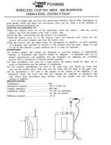
1. Unit Features and Functions
Figure 11
1. Grill/Ball Screen: incorporates a combination
pop/wind filter and protects the microphone
capsule.
2. Battery compartment: Accepts a standard/
universal 9-volt. Simply unscrew the grill/ball
screen to access this compartment.
3. Housing/handle: finished in a durable rubber
velvet material for operator comfort.
4. Battery status indicator: A ‘flash’ at turn on
indicates that the batter is OK. No flash at turn
14
1
2 3
6
4
5

on indicates that the battery is either dead or
not installed. A constant glow indicates a weak
batter that should be replaced.
5. On-Of switch. Push forward to turn the
transmitter on and slide back to turn the
transmitter off. RF signal is transmitted almost
immediately the switch is turned on (and the
corresponding RF present lamp will glow on
the receiver), setting the receiver in to ‘stand
by’ mode. AF signal is only transmitted when a
RF link is active and the microphone threshold
is opened, i.e. by speech.
6. Group and channel selector cover: push this
cover down and back as indicated to access
the group and channel selector switches.
7. Group selector switch: make sure this setting
matches the group selection on the receiver.
(Under group and channel selector cover.)
8. Channel selector switch: make sure this
setting matches the channel selection on the
receiver. (Under group and channel selector
cover.)
9. Unavailable setting indicator. This led glows
(when the transmitter has been powered on) if
you select a switch combination that has no
connection. (Under group and channel
selector cover..)
15

16
2. BATTERY INSTALLATION
Fig.12
1. Unscrew the grill/ball screen assembly at the
collar to expose the battery compartment.
2. Insert the 9-volt battery taking care to observe
the correct polarity. If the polarity is correct,
the battery status indicator lamp will flash
briefly. If no flash is observed, then it is likely
the polarity is incorrect or the battery is dead
flat and needs to be replaced.
3. Replace the grill/ball screen assembly, taking
care to line up the 3 pins and polarizing lug
with the 3 contractor plates. Screw the grill/ball
screen back in to place, taking care not to
force the turns. The turns should be smooth
and easy. If the grill/ball screen assembly
appears to either not engage, or tries to cross
thread, remove it and check for the correct
alignment of the pins.
2. OPERATION OF THE HAND HELD TRANSMITTER
When the microphone is switched on, the led indicator will
flash briefly to indicate that the battery is OK and that the
transmitter is powered up. At the receiver, the RF indicator
will illuminate almost immediately to indicate that a RF link
has been established and the AF indicator will illuminate

once audio is present. As mentioned previously, the level of
these two indicators will indicate their signal strength at the
receiver. When the microphone is not in use, please switch
it off to conserve the battery
BELT PACK TRANSMITTER
Figure 14
Like the receiver, the belt pack transmitter features
advanced synthesized PLL design. It is preprogrammed
with 30 user selectable frequencies and incorporates
Pilotone and Noise Lock dual squelch circuitry. The
transmitter is capable of connection to a variety of input
sources including lapel microphones, headworn
microphones, guitars and other line level output devices.
1. Audio input connector. This accepts a variety
of input levels and types. Please refer to page
21 for details of the various connections
options available. It is important that the right
1
7
2
3
4
5
10
9
6
8
17

18
connection is used. If you are having problems
with a system, this is one of the first places to
look for the solution.
2. Transmit antenna: 1/4 wave
3. GT/MT level selector switch: This switch works
in combination with the way you have wired
the input device (as detailed above). Set this
switch in the GT position if you are connecting
to the output of and electric guitar. Set the
switch to the MT position for all other
connections.
4. Gain control: this control works when the
GT/MT selector switch is in the MT position
only. It provides the user with a small range of
independent system level control. Once set, it
should be left alone to avoid the user causing
self inflicted embarrassment by crossing the
threshold of feedback or reducing the output
to an inaudible level.
5. Transmitter housing: made from heavy duty
poly-plastic with a discreet low profile and
smooth contoured shape for wearer comfort.
6. Battery status indicator: A ‘flash’ at turn on
indicates that the batter is OK. No flash at turn
on indicates that the battery is dead or not
installed. A constant glow indicates a weak
battery that should be replaced.
7. Power switch: turns power to the transmitter
on and off. A RF link (if available) is opened
immediately the transmitter is switched on. An
AF link is established when a suitable audio

signal is present at the input (from a lapel
microphone, guitar etc)
8. Unused status indicator: this illuminates when
the combination of group and channel you
have selected is not connected.
9. Group selector switch: make sure this setting
matches the group selection on the receiver.
10. Channel selector switch: make sure this
setting matches the channel selection on the
receiver.
11. Battery compartment and cover: accepts one
standard 9V battery. (Figure 14)
2. OPERATION OF THE BELT PACK TRANSMITTER
Figure 14
1. Push ‘down and out’ to open the battery
compartment.
2. Insert the battery making sure that correct
polarity is observed. Close the battery cover
as shown in figure 15.
19
11

20
3. Select a group/channel combination, making
sure that it matches the combination already
set on the receiver.
4. Connect your lapel microphone, guitar lead, or
other input. Connection details are as per
figure 15.
5. Adjust the gain control on the belt pack to the
desired level.
Figure 15

1. AF 4-PIN INPUT CONNECTION METHODS
1. 2-Wire Electret condenser microphone Capsule
2. 3-Wire Electret condenser microphone Capsule
3. Dynamic Microphone
4. Electric Guitar
5. Line-in (Impedance 8KΩ Attenuated 10 dB)
21
/