ProForm 495Pi PFTL33105.0 User manual
- Category
- Treadmills
- Type
- User manual
This manual is also suitable for

M
odel No. PFTL33105.0
Serial No.
CAUTION
Read all precautions and instruc-
tions in this manual before using
this equipment. Save this manual
for future reference.
Serial Number
Decal
USER'S MANUAL
QUESTIONS?
As a manufacturer, we are com-
mitted to providing complete
customer satisfaction. If you
have questions, or if parts are
damaged or missing, PLEASE
CONTACT OUR CUSTOMER
SERVICE DEPARTMENT DI-
RECTLY.
CALL TOLL-FREE:
1-888-533-1333
Mon.–Fri., 6 a.m.–6 p.m. MST
ON THE WEB:
www.proformservice.com
Visit our website at
www.proform.com
new products, prizes,
fitness tips, and much more!
V

TABLE OF CONTENTS
IMPORTANT PRECAUTIONS . . . . . . . . . . . . . . . . . . . . . . . . . . . . . . . . . . . . . . . . . . . . . . . . . . . . . . . . . . . . . . . .3
BEFORE YOU BEGIN . . . . . . . . . . . . . . . . . . . . . . . . . . . . . . . . . . . . . . . . . . . . . . . . . . . . . . . . . . . . . . . . . . . . . .5
ASSEMBLY . . . . . . . . . . . . . . . . . . . . . . . . . . . . . . . . . . . . . . . . . . . . . . . . . . . . . . . . . . . . . . . . . . . . . . . . . . . . . . .6
OPERATION AND ADJUSTMENT . . . . . . . . . . . . . . . . . . . . . . . . . . . . . . . . . . . . . . . . . . . . . . . . . . . . . . . . . . . .11
HOW TO FOLD AND MOVE THE TREADMILL . . . . . . . . . . . . . . . . . . . . . . . . . . . . . . . . . . . . . . . . . . . . . . . . . .14
TROUBLESHOOTING . . . . . . . . . . . . . . . . . . . . . . . . . . . . . . . . . . . . . . . . . . . . . . . . . . . . . . . . . . . . . . . . . . . . .16
CONDITIONING GUIDELINES . . . . . . . . . . . . . . . . . . . . . . . . . . . . . . . . . . . . . . . . . . . . . . . . . . . . . . . . . . . . . . .18
HOW TO ORDER REPLACEMENT PARTS . . . . . . . . . . . . . . . . . . . . . . . . . . . . . . . . . . . . . . . . . . . . .Back Cover
LIMITED WARRANTY . . . . . . . . . . . . . . . . . . . . . . . . . . . . . . . . . . . . . . . . . . . . . . . . . . . . . . . . . . . . . .Back Cover
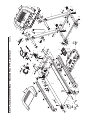
Note: An EXPLODED DRAWING and a PART LIST are attached in the center of this manual.
2
PROFORM is a registered trademark of ICON IP, Inc.

1. It is the responsibility of the owner to ensure
that all users of this treadmill are adequately
informed of all warnings and precautions.
2. Use the treadmill only as described.
3. Place the treadmill on a level surface, with at
least eight feet of clearance behind it and two
feet on each side. Do not place the treadmill
on any surface that blocks air openings. To
protect the floor or carpet from damage, place
a mat under the treadmill.
4. Keep the treadmill indoors, away from mois-
ture and dust. Do not put the treadmill in a
garage or covered patio, or near water.
5. Do not operate the treadmill where aerosol
products are used or where oxygen is being
administered.
6. Keep children under the age of 12 and pets
away from the treadmill at all times.
7. The treadmill should be used only by persons
weighing 250 pounds or less.
8. Never allow more than one person on the
treadmill at a time.
9. Wear appropriate exercise clothes when
using the treadmill. Do not wear loose clothes
that could become caught in the treadmill.
Athletic support clothes are recommended for
both men and women.
Always wear athletic
shoes. Never use the treadmill with bare feet,
wearing only stockings, or in sandals.
10.
When connecting the power cord (see page 11),
plug the power cord into a surge suppressor
(not included) and plug the surge suppressor
into a grounded circuit capable of carrying 15
or more amps. No other appliance should be on
the same circuit. Do not use an extension cord.
11. Use only a single-outlet surge suppressor that
meets all of the specifications described on
page 11. To purchase a surge suppressor, see
your local PROFORM dealer or call the toll-
free telephone number on the front cover of
this manual and order part number 146148, or
see your local electronics store.
12. Failure to use a properly functioning surge
suppressor could result in damage to the con-
trol system of the treadmill. If the control sys-
tem is damaged, the walking belt may change
speed, accelerate, or stop unexpectedly,
which may result in a fall and serious injury.
13. Keep the power cord and the surge suppres-
sor away from heated surfaces.
14. Never move the walking belt while the power
is turned off. Do not operate the treadmill if
the power cord or plug is damaged, or if the
treadmill is not working properly. (See TROU-
BLESHOOTING on page 16 if the treadmill is
not working properly.)
15. Never start the treadmill while you are stand-
ing on the walking belt. Always hold the
handrails while using the treadmill.
16. The treadmill is capable of high speeds.
Adjust the speed in small increments to avoid
sudden jumps in speed.
17. The pulse sensor is not a medical device.
Various factors, including your movement,
may affect the accuracy of heart rate readings.
The sensor is intended only as an exercise aid
in determining heart rate trends in general.
18. Do not use the hand weights at speeds faster
than walking speeds. Using weights and not
holding the handrails may compromise your
ability to maintain your balance. Exercises
using weights should be attempted only by
experienced users.
19. Never leave the treadmill unattended while it
is running. Always remove the key and unplug
the power cord when the treadmill is not in
use.
20. Do not attempt to raise, lower, or move the
treadmill until it is properly assembled. (See
ASSEMBLY on page 6, and HOW TO FOLD
AND
MOVE
THE
TREADMILL on page 14.)
You must be able to safely lift 45 pounds (20
kg) to raise, lower, or move the treadmill.
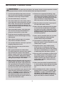
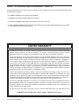
WARNING: T
o reduce the risk of burns, fire, electric shock, or injury to persons, read the
following important precautions and information before operating the treadmill.
IMPORTANT PRECAUTIONS
3

4
21. When folding or moving the treadmill, make
sure that the storage latch is fully closed.
2
2. Inspect and properly tighten all parts of the
treadmill regularly.
23. Never insert any object into any opening.
24. DANGER: Always unplug the power
cord immediately after use, before cleaning
the treadmill, and before performing the
maintenance and adjustment procedures de-
s
cribed in this manual. Never remove the
motor hood unless instructed to do so by an
authorized service representative. Servicing
o
ther than the procedures in this manual
should be performed by an authorized ser-
vice representative only.
25. This treadmill is intended for in-home use
only. Do not use this treadmill in a commer-
cial, rental, or institutional setting.
WARNING: Before beginning this or any exercise program, consult your physician. This
is especially important for persons over the age of 35 or persons with pre-existing health problems.
Read all instructions before using. ICON assumes no responsibility for personal injury or property
damage sustained by or through the use of this product.
SAVE THESE INSTRUCTIONS
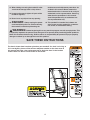
The decals shown here have been placed on your treadmill. If a decal is missing, or
if it is not legible, please call the toll-free telephone number on the front cover of
this manual and order a free replacement decal. Apply the decal in the location
shown. Note: The decals are not shown at actual size.

5
T
hank you for selecting the new PROFORM
®
4
95 Pi
t
readmill. The 495 Pi treadmill combines advanced tech-
nology with innovative design to help you get the most
from your exercise in the convenience of your home.
And when you’re not exercising, the 495 Pi treadmill can
be folded up, requiring less than half the floor space of
other treadmills.
For your benefit, read this manual carefully before
using the treadmill. If you have questions after read-
ing this manual, see the front cover of this manual. To
help us assist you, please note the product model
n
umber and serial number before calling. The model
n
umber of the treadmill is PFTL33105.0. The serial
number can be found on a decal attached to the tread-
mill (see the front cover of this manual for the location).
To avoid a registration fee for any service needed
under warranty, you must register the treadmill at
www.proformservice.com/registration.
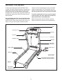
Before reading further, please review the drawing
below and familiarize yourself with the labeled parts.
BEFORE YOU BEGIN
Handrail
Upright
Storage Latch
Key/Clip
Reset/Off
Circuit Breaker
Walking Belt
Cushioned Walking Platform
for maximum exercise comfort
Foot Rail
Power Cord
RIGHT SIDE
Rear Roller
Adjustment Bolts
Console
Fan
Accessory Tray
BACK

ASSEMBLY
To hire an authorized service technician to assemble the treadmill, call toll-free 1-800-445-2480.
Assembly requires two persons.
Set the treadmill in a cleared area and remove all packing materials. Do not
dispose of the packing materials until assembly is completed. Note: The underside of the treadmill walking belt is
coated with high-performance lubricant. During shipping, a small amount of lubricant may be transferred to the
top of the walking belt or the shipping carton. This is a normal condition and does not affect treadmill perfor-
mance. If there is lubricant on top of the walking belt, simply wipe off the lubricant with a soft cloth and a mild,
non-abrasive cleaner.
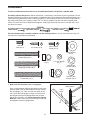
Assembly requires the included allen wrenches and your own phillips screwdriver ,
rubber mallet , adjustable wrench , and wire cutters .
For help identifying the assembly hardware, see the drawings below.
If a part is not in the parts bag, first
check to see if it has been pre-assembled.
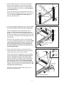
1. Make sure that the power cord is unplugged.
Have a second person hold the Upright Base (48) in the
position shown, with the wheel holes at the top. Identify
the Left Upright (31), which has two latch holes in one
side. Orient the Left Upright as shown, and attach it to
the Upright Base with two Upright Bolts (40) and two
Upright Star Washers (39).
Do not tighten the Upright
Bolts yet. Note: There may be left and right stickers on
the Uprights and on the Upright Base.
Handrail Star
Washer (19)–4
1
Nut (47)–4
Frame Bolt (32)–2
Console
Bolt (22)–2
3/4” Screw (2)–6
Upright/Wheel Bolt (40)–6
Upright Star
Washer (39)–4
Frame Washer
(33)–2
1/4” Star Washer
(21)–2
Handrail Bolt (20)–4
Silver Ground
Screw (27)–2
Wheel Spacer
(44)–4
48
Wheel Holes
Latch
Holes
40
39
31
1
6

7
2. Orient the Right Upright (36) so that the square hole at
t
he lower end is oriented as shown. Attach the Right
Upright to the Upright Base (48) with two Upright Bolts
(
40) and two Upright Star Washers (39).
D
o not tighten
the Upright Bolts yet.
Attach each Wheel (45) to the Upright Base (48) with a
W
heel Bolt (40), two Wheel Spacers (44), and a Nut (47)
a
s shown.
D
o not overtighten the Wheel Bolts;
t
he
Wheels should turn freely.
48
Square Hole
45
47
44
40
4
5
44
36
4
4
40
47
2
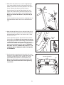
3.
Cut the tie holding the Upright Wire (28) in a bundle.
Leave
the large colored tie on the end of the Upright Wire.
Orient the Upright Base (48) on the Wheels (45) as
shown, and center the frame assembly between the
Uprights (31, 36). With the help of another person, lower
the frame assembly and insert the Wire Harness (28) into
the large hole at the bottom of the Right Upright (36) and
out of the top.
While the frame assembly is raised, raise the Uprights
(31, 36) so the Upright Base (48) is flat on the floor.
Make
sure that the end of the Wire Harness (28) does not
fall into the Right Upright (36). It may be helpful to
bend the colored tie on the end of the Wire Harness
over the Right Upright.
28
Colored Tie
48
28
36
31
45
3
4. Orient the two Frame Spacers as shown in the inset
drawing. Open the included packet of grease and apply
equally to both sides of each Frame Spacer.
Hold a Frame Spacer (34) between the frame assembly
and the Right Upright (36). Make sure that the Frame
Spacer is oriented as shown in the inset drawing.
Insert a Frame Bolt (32) through a Frame Washer (33),
the Right Upright, and the Frame Spacer and through
the bracket on the frame assembly. Be careful not to
pinch the Wire Harness (28) in the Right Upright (36).
Tighten a Nut (47) onto the Frame Bolt several turns. Do
not tighten the Frame Bolt yet.
Repeat this step on the left side. Note: There is not a
wire harness on the left side.
Frame Assembly
Bracket
Frame Assembly
Hole
32
34
33
4
47
28
36
Right
Side
Left
Side
34
40
39

8
28
18
6. Hold the Console Base (26) near the right Handrail (18).
Attach the end of the ground wire on the Console Base
to the indicated small hole in the Handrail with a Silver
Ground Screw (27).
Connect the Wire Harness (28) to wire harness on the
Console Base (26).
Make sure to connect the connec-
tors properly (see the inset drawing). The connectors
should slide together easily and snap into place. If
the connectors do not slide together easily and snap into
place, turn one connector and try again. IF THE CON-
NECTORS ARE NOT CONNECTED PROPERLY, THE
CONSOLE MAY BE DAMAGED WHEN THE POWER
IS TURNED ON.
27
26
Ground
Wire
22
7. Set the console assembly on the Handrails (18); insert
the excess wiring down into the right Handrail. Attach the
console assembly with four 3/4” Screws (2) and two
Console Bolts (22) with two 1/4” Star Washers (21).
Make sure that no wires are pinched. Start all four
Screws and both Console Bolts before tightening
any of them.
2
22
21
21
2
18
18
6
7
5
. Hold one of the Handrails (18) near the Right Upright
(36). Insert the Wire Harness (28) into the hole in the
bottom of the Handrail and out of the hole in the top as
shown. Remove the tie from the Wire Harness.
Set the Handrail (18) on the Right Upright (36), and
tighten two Handrail Bolts (20) with two Handrail Star
Washers (19) into the Handrail and the Right Upright.
M
ake sure that the Wire Harness (28) does not get
pinched.
Attach the other Handrail (18) to the Left Upright (31) as
described above. Note: There is not a wire on the left
side.
36
31
28
20
19
1
8
19
20
18
5
28
Console Assembly

8. Lower the Uprights (31, 36) until the Handrails (18) are
touching the floor.
See the lower drawing. Position the Uprights (31, 36) so
t
hat the treadmill Frame (74) is centered between the
Uprights.
Firmly tighten the four Upright Bolts (40) and the two
Frame Bolts (32). Be careful not to overtighten the
Frame Bolts.
31
31, 36
32
18
74
36
Top View
8
40
9. Attach the end of the ground wire from the Wire Harness
(28) to the indicated small hole in the Upright Base (48)
with a Silver Ground Screw (27).
Make sure that the grommet is pressed into the side of the
Right Upright (36).
Raise the Uprights (36, 31) to the vertical position.
48
28
36
Grommet
9
27
Ground
Wire
9

10
11. Make sure that all parts are properly tightened before you use the treadmill. Note: Extra hardware may
be included. Keep the included allen wrenches in a secure place; the large allen wrench is used to adjust the
walking belt (see page 17). To protect the floor or carpet, place a mat under the treadmill.
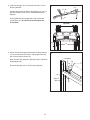
10 Attach the Latch Housing (30) to the Left Upright (31) with
two 3/4” Screws (2). Make sure that the large hole in
t
he Latch Housing is on the side shown. Do not over-
tighten the Screws.
Remove the knob from the pin. Make sure that the collar
and the spring are on the pin as shown. Insert the pin into
the Latch Housing (30), and tighten the knob back onto
the pin.
2
3
0
31
1
0
Knob
Pin
Collar
Spring

1
1
OPERATION AND ADJUSTMENT
T
HE PRE-LUBRICATED WALKING BELT
Your treadmill features a walking belt coated with high-
performance lubricant. IMPORTANT: Never apply sil-
icone spray or other substances to the walking
belt or the walking platform. Such substances will
deteriorate the walking belt and cause excessive
wear.
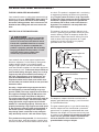
HOW TO PLUG IN THE POWER CORD
Your treadmill, like any other type of sophisticated
electronic equipment, can be seriously damaged by
sudden voltage changes in your home’s power.
Voltage surges, spikes, and noise interference can
result from weather conditions or from other appliances
being turned on or off. To decrease the possibility of
your treadmill being damaged, always use a surge
suppressor with your treadmill (see drawing 1 at
the right). To purchase a surge suppressor, see
your local PROFORM dealer or call the toll-free
telephone number on the front cover of this man-
ual and order part number 146148, or see your local
electronics store.
Use only a single-outlet surge suppressor that is
UL 1449 listed as a transient voltage surge sup-
pressor (TVSS). The surge suppressor must have a
UL suppressed voltage rating of 400 volts or less
and a minimum surge dissipation of 450 joules.
The surge suppressor must be electrically rated for
120 volts AC and 15 amps. There must be a moni-
toring light on the surge suppressor to indicate
whether it is functioning properly. Failure to use a
properly functioning surge suppressor could result
in damage to the control system of the treadmill. If
the control system is damaged, the walking belt
may change speed, accelerate or stop unexpect-
edly, which may result in a fall and serious injury.
This product must be grounded.
If it should malfunc-
tion or break down, grounding provides a path of least
resistance for electric current to reduce the risk of elec-
t
ric shock. This product is equipped with a cord having
an equipment-grounding conductor and a grounding
plug.
Plug the power cord into a surge suppressor,
and plug the surge suppressor into an appropriate
outlet that is properly installed and grounded in
accordance with all local codes and ordinances.
Important: The treadmill is not compatible with
GFCI-equipped outlets.
This product is for use on a nominal 120-volt circuit,
and has a grounding plug that looks like the plug illus-
trated in drawing 1 below. A temporary adapter that
looks like the adapter illustrated in drawing 2 may be
used to connect the surge suppressor to a 2-pole
receptacle as shown in drawing 2 if a properly
grounded outlet is not available.
The temporary adapter should be used only until a
properly grounded outlet (drawing 1) can be installed
by a qualified electrician.
The green-colored rigid ear, lug, or the like extending
from the adapter must be connected to a permanent
ground such as a properly grounded outlet box cover.
Whenever the adapter is used it must be held in place
by a metal screw.
Some 2-pole receptacle outlet box
covers are not grounded. Contact a qualified elec
-
trician to determine if the outlet box cover is
grounded before using an adapter.
DANGER: Improper connection
of the equipment-grounding conductor can
result in an increased risk of electric shock.
Check with a qualified electrician or service-
man if you are in doubt as to whether the
product is properly grounded. Do not modify
the plug provided with the product—if it will
not fit the outlet, have a proper outlet
installed by a qualified electrician.
1
2
Grounded Outlet Box
Grounded Outlet Box
Grounding Plug
Surge Suppressor
Surge Suppressor
Grounding Pin
Adapter
Lug
Metal Screw
Grounded Outlet
Grounding Pin

12
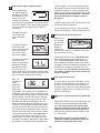
STEP-BY-STEP CONSOLE OPERATION
Note: To prevent damage to the walking platform,
always wear clean shoes when using the treadmill.
Before operating the console, make sure that the
power cord is properly plugged in (see page 11).
In addition, locate the
reset/off circuit breaker on
the treadmill frame near the
power cord, and make sure
that the circuit breaker is in
the reset position.
Next, stand on the foot rails of the treadmill. Find the
clip attached to the key (see the drawing above), and
slide the clip onto the waistband of your clothes. Then,
insert the key into the console. After a moment, the
display will light. Test the clip by carefully taking a
few steps backward until the key is pulled from the
console. If the key is not pulled from the console,
adjust the position of the clip.
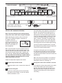
Follow the steps below to operate the console.
Insert the key into the console.
A moment after the key is inserted, the display will
light.
Start
the walking belt.
To start the walking belt, press the Start button,
the Speed increase button, or one of the speed
buttons numbered 1 to 10.
If the Start button or the Speed increase button is
pressed, the walking belt will begin to move at 1
mph. As you exercise, change the speed of the
walking belt as desired by pressing the Speed in-
crease and decrease buttons. Each time a button
is pressed, the speed setting will change by 0.1
mph; if a button is held down, the speed setting
will change in increments of 0.5 mph. Note: After
the buttons are pressed, it may take a moment for
the walking belt to reach the selected speed setting.
If one of the numbered speed buttons is pressed,
the walking belt will gradually change in speed until
it reaches the selected speed setting.
To stop the walking belt, press the Stop button.
The elapsed time will begin to
flash in the display.
To restart the walking belt, press the Start button,
the Speed increase button, or one of the numbered
speed buttons.
Note: The first time the treadmill is used, observe
the alignment of the walking belt, and center the
walking belt if necessary (see page 17).
Change the incline of the treadmill as desired.
To change the incline of the treadmill, press either
of the I
ncline
buttons. Each time a button is
pressed, the incline setting will change by 0.5%.
Note: After the buttons are pressed, it may take a
moment for the treadmill to reach the selected in
-
cline setting.
3
2
1
Clip
Key
Note: If there is a thin sheet of
plastic on the console, remove it.
CONSOLE DIAGRAM
Reset

13
Follow your progress with the display.
A track representing
1/4 mile will appear in
the upper right corner
o
f the display. As you
walk or run on the
treadmill, the indicators
around the track will appear in succession until the
entire track appears. The track will then disappear
and the indicators will again begin to appear in
succession.
The upper left corner
of the display will
show the elapsed
time.
The lower left corner
of the display will
show the distance that
you have walked or
run and the incline
level of the treadmill.
The lower right corner
of the display will
show the speed of the
walking belt and the
approximate number
of calories that you
have burned during your workout. The lower right
corner of the display will also show your heart rate
when you use the handgrip pulse sensor.
Note: The
console can
display
speed and
distance in
either miles
or kilome
ters. To see which unit of measurement
is selected, select the console’s information mode
by holding down the Stop button, inserting the key
into the console, and then releasing the Stop but-
ton. An “E” for English miles or an “M” for metric
kilometers will appear in the display. Press the
Speed increase
button to change the unit of mea
-
surement if desired. When the information mode is
selected, the console will also show the total num
-
ber of hours that the treadmill has been used and
the total distance that the walking belt has moved
since the treadmill was purchased.
Important: If a
“d” appears in the display, the console is in the
“demo” mode. This mode is intended to be used
only when a treadmill is displayed in a store. When
the console is in the demo mode, the power cord
can be plugged in, the key can be removed from
the console, and the indicators in the display will
a
utomatically appear in a preset sequence; the
buttons on the console will not operate.
If a “d” ap-
p
ears when the information mode is selected,
press the Speed decrease button so the “d”
disappears.
To exit the information mode, remove the key from
the console and then reinsert it.
To reset the display at any time, press the Stop
button, remove the key, and then reinsert the key.
Measure your heart rate if desired.
Before using
the handgrip
pulse sensor,
remove the
sheets of
clear plastic
from the metal contacts. In addition, make sure
that your hands are clean.
To measure your heart rate,
stand on the foot
rails and place your hands on the metal con-
tacts—avoid moving your hands. When your
pulse is detected, the heart symbol in the display
will begin to flash each time your heart beats, one
or two dashes will appear, and then your heart
rate will be shown. For the most accurate heart
rate reading, continue to hold the contacts for
about 15 seconds.
Turn on the fan if desired.
To turn on the fan, press the Fan button. To turn
on the fan at high speed, press the button a sec-
ond time. To turn off the fan, press the button a
third time. Note: If the fan is left on when the walk
-
ing belt is stopped, the fan will automatically turn
off after a few minutes.
When you are finished exercising, remove the
key.
Step onto the foot rails, press the Stop button, and
adjust the incline of the treadmill to the lowest
level. The incline must be at the lowest level
when the treadmill is raised to the storage po
-
sition or the treadmill will be damaged. Next,
remove the key from the console and put the key
in a secure place.
When you are finished using the treadmill,
switch the reset/off circuit breaker to the “off”
position and unplug the power cord.
7
6
5
4
Metal Contacts

14
HOW TO FOLD AND MOVE THE TREADMILL
HOW TO FOLD THE TREADMILL FOR STORAGE
Before folding the treadmill, adjust the incline to the
lowest position. If this is not done, the treadmill may be per-
m
anently damaged. Next, unplug the power cord. CAUTION:
You must be able to safely lift 45 pounds (20 kg) to raise,
lower, or move the treadmill.
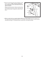
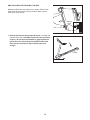
1. Hold the metal frame firmly in the location shown by the
arrow at the right. CAUTION: To decrease the possibility
of injury, do not lift the treadmill by the plastic foot rails.
Make sure you bend your legs and keep your back
straight. As you raise the treadmill, make sure to lift with
your legs rather than your back.
Raise the treadmill about
halfway to the vertical position.
2. Move your right hand to the position shown and hold the
treadmill firmly. Using your left hand, pull the latch knob to
the left and hold it. Raise the frame until the hole in the frame
is aligned with the latch pin, and then slowly release the latch
knob.
Make sure that the latch pin is fully inserted into
the frame.
To protect the floor or carpet from damage, place a mat
under the treadmill. Keep the treadmill out of direct sun-
light. Do not leave the treadmill in the storage position in
temperatures above 85° Fahrenheit.
HOW TO MOVE THE TREADMILL
Before moving the treadmill, convert the treadmill to the storage
position as described above. Make sure that the latch pin is
fully inserted into the storage latch.
1.
Hold onto one handrail and place the hand on the deck.
Place one foot against one of the wheels.
2.
Tilt the treadmill back until it rolls freely on the wheels.
Carefully move the treadmill to the desired location. To re-
duce the risk of injury, use extreme caution while mov
-
ing the treadmill.
Do not move the treadmill over an un
-
even surface.
3.
Place one foot against one of the wheels, and carefully lower
the treadmill until it is resting in the storage position.
Base
Handrails
Deck
Wheels
Engaged
Catch
Storage
Latch
Frame

15
HOW TO LOWER THE TREADMILL FOR USE
Hold the treadmill with your right hand as shown. Pull the latch
knob to the left and hold it. Pivot the treadmill down until the
frame is past the latch pin.
2. Hold the metal frame firmly with both hands, and lower the
treadmill to the floor. CAUTION: To decrease the possibility
of injury, do not lower the treadmill by gripping only the
plastic foot rails. Do not drop the treadmill frame to the
floor. Be sure to bend your legs and keep your back
straight.
Catch
Frame
Storage
Latch

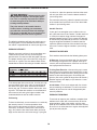
TROUBLESHOOTING
Most treadmill problems can be solved by following the steps below. Find the symptom that applies, and
follow the steps listed. If further assistance is needed, please call the toll-free telephone number on the
f
ront cover of this manual.
PROBLEM: The power does not turn on
SOLUTION:
a. Make sure that the power cord is plugged into a surge suppressor, and that the surge suppressor
is plugged into a properly grounded outlet (see page 11). Use only a single-outlet surge suppres-
sor that meets all of the specifications described on page 11. Important: The treadmill is not com-
patible with GFCI-equipped outlets.
b. After the power cord has been plugged in, make sure that the key is fully inserted into the console.
c. Check the reset/off circuit breaker located on the
treadmill frame near the power cord. If the switch
protrudes as shown, the circuit breaker has tripped.
To reset the circuit breaker, wait for five minutes
and then press the switch back in.
PROBLEM: The power turns off during use
SOLUTION: a. Check the circuit breaker located on the treadmill frame near the power cord (see the drawing
above). If the circuit breaker has tripped, wait for five minutes and then press the switch back in.
b. Make sure that the power cord is plugged in. If the power cord is plugged in, unplug it, wait for
five minutes, and then plug it back in.
c. Remove the key from the console. Reinsert the key fully into the console.
d. If the treadmill still will not run, see the front cover of this manual.
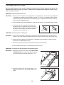
PROBLEM: The displays of the console do not function properly
SOLUTION: a. Remove the key from the console and UNPLUG THE
POWER CORD. Remove the eight Foot Rail Screws
(4) and lift of the Left and Right Foot Rails (3, 75).
b. Remove the two Screws (2) from the Hood (1) and
the two Tab Screws (A), and carefully remove the
Hood.
Tripped
Reset
c
4
4
4
4
3
75
a
A
A
1
2
4
b
16

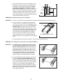
17
c. Locate the Reed Switch (63) and the Magnet (67) on
the left side of the Pulley (64). Turn the Pulley until
t
he Magnet is aligned with the Reed Switch. M
ake
sure that the gap between the Magnet and the
R
eed Switch is about 1/8”.
I
f necessary, loosen the
Screw (11), move the Reed Switch slightly, and then
retighten the Screw. Reattach the Hood (see step b),
and run the treadmill for a few minutes to check for a
correct speed reading. If the reading appears normal,
reattach the Foot Rails (see step a).
PROBLEM: The walking belt slows when walked on
SOLUTION:
a. Use only a single-outlet surge suppressor that meets all of the specifications described on page 11.
b. If the walking belt is overtightened, treadmill perfor-
mance may decrease and the walking belt may be-
come damaged. Remove the key and UNPLUG THE
POWER CORD. Using the allen wrench, turn both
rear roller adjustment bolts counterclockwise, 1/4 of a
turn. When the walking belt is properly tightened, you
should be able to lift each edge of the walking belt 2
to 3 inches off the walking platform. Be careful to
keep the walking belt centered. Plug in the power
cord, insert the key, and run the treadmill for a few
minutes. Repeat until the walking belt is properly tight-
ened.
c. If the walking belt still slows when walked on, see the front cover of this manual.
PROBLEM: The walking belt is off-center or slips when walked on
SOLUTION: a. If the walking belt is off-center, first remove the key
and UNPLUG THE POWER CORD. If the walking
belt has shifted to the left, use the allen wrench to
turn the left rear roller bolt clockwise 1/2 of a turn; if
the walking belt has shifted to the right, turn the
left bolt counterclockwise 1/2 of a turn. Be careful not
to overtighten the walking belt. Plug in the power
cord, insert the key, and run the treadmill for a few
minutes. Repeat until the walking belt is centered.
b. If the walking belt slips when walked on, first remove
the key and
UNPLUG THE POWER CORD. Using
the allen wrench, turn both rear roller bolts clockwise,
1/4 of a turn. When the walking belt is correctly tight-
ened, you should be able to lift each edge of the walk-
ing belt 2 to 3 inches off the walking platform. Be
careful to keep the walking belt centered. Plug in the
power cord, insert the key, and carefully walk on the
treadmill for a few minutes. Repeat until the walking
belt is properly tightened.
Rear Roller Adjustment Bolts
2”–3”
b
a
b
67
6
3
11
Top
View
1/8”
6
4
c

18
CONDITIONING GUIDELINES
The following guidelines will help you to plan your ex-
ercise program. For more detailed exercise informa-
tion, obtain a reputable book or consult your physician.
EXERCISE INTENSITY
Whether your goal is to burn fat or to strengthen your
cardiovascular system, the key to achieving the
desired results is to exercise with the proper intensity.
The proper intensity level can be found by using your
heart rate as a guide. The chart below shows recom-
mended heart rates for fat burning and aerobic exercise.
To find the proper heart rate for you, first find your age
near the bottom of the chart (ages are rounded off to
the nearest ten years). Next, find the three numbers
above your age. The three numbers define your “train-
ing zone.” The lower two numbers are recommended
heart rates for fat burning; the higher number is the
recommended heart rate for aerobic exercise.
Fat Burning
To burn fat effectively, you must exercise at a relatively
low intensity level for a sustained period of time.
During the first few minutes of exercise, your body
uses easily accessible
carbohydrate calories
for en-
ergy. Only after the first few minutes does your body
begin to use stored
fat calories
for energy. If your goal
is to burn fat, adjust the speed and incline of the tread-
mill until your heart rate is near the lowest number in
y
our training zone.
For maximum fat burning, adjust the speed and incline
of the treadmill until your heart rate is near the middle
number in your training zone.
Aerobic Exercise
If your goal is to strengthen your cardiovascular sys-
tem, your exercise must be “aerobic.” Aerobic exercise
is activity that requires large amounts of oxygen for
prolonged periods of time. This increases the demand
on the heart to pump blood to the muscles, and on the
lungs to oxygenate the blood. For aerobic exercise,
adjust the speed and incline of the treadmill until your
heart rate is near the highest number in your training
zone.
WORKOUT GUIDELINES
Each workout should include the following three parts:
A Warm-up—Start each workout with 5 to 10 minutes
of stretching and light exercise. A proper warm-up in-
creases your body temperature, heart rate and circula-
tion in preparation for exercise.
Training Zone Exercise—After warming up, increase
the intensity of your exercise until your pulse is in your
training zone for 20 to 60 minutes. (During the first few
weeks of your exercise program, do not keep your
pulse in your training zone for longer than 20 minutes.)
Breathe regularly and deeply as you exercise—never
hold your breath.
A Cool-down—Finish each workout with 5 to 10 min
-
utes of stretching to cool down. This will increase the
flexibility of your muscles and will help prevent post-
exercise problems.
EXERCISE FREQUENCY
To maintain or improve your condition, complete three
workouts each week, with at least one day of rest be-
tween workouts. After a few months, you may com-
plete up to five workouts each week if desired. The key
to success is to make exercise a regular and enjoyable
part of your everyday life.
WARNING: Before beginning this
or any exercise program, consult your physi-
c
ian. This is especially important for individu-
als over the age of 35 or individuals with pre-
existing health problems.
The pulse sensor is not a medical device.
Various factors, including your movement,
may affect the accuracy of heart rate readings.
The sensor is intended only as an exercise aid
in determining heart rate trends in general.

19
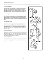
SUGGESTED STRETCHES
T
he correct form for several basic stretches is shown at the right. Move slowly as you stretch—never bounce.
1
. Toe Touch Stretch
Stand with your knees bent slightly and slowly bend forward from
your hips. Allow your back and shoulders to relax as you reach
down toward your toes as far as possible. Hold for 15 counts, then
relax. Repeat 3 times. Stretches: Hamstrings, back of knees and
back.
2. Hamstring Stretch
Sit with one leg extended. Bring the sole of the opposite foot toward
you and rest it against the inner thigh of your extended leg. Reach
toward your toes as far as possible. Hold for 15 counts, then relax.
Repeat 3 times for each leg. Stretches: Hamstrings, lower back and
groin.
3. Calf/Achilles Stretch
With one leg in front of the other, reach forward and place your
hands against a wall. Keep your back leg straight and your back
foot flat on the floor. Bend your front leg, lean forward and move
your hips toward the wall. Hold for 15 counts, then relax. Repeat 3
times for each leg. To cause further stretching of the achilles ten-
dons, bend your back leg as well. Stretches: Calves, achilles ten-
dons and ankles.
4. Quadriceps Stretch
With one hand against a wall for balance, reach back and grasp one
foot with your other hand. Bring your heel as close to your buttocks
as possible. Hold for 15 counts, then relax. Repeat 3 times for each
leg. Stretches: Quadriceps and hip muscles.
5. Inner Thigh Stretch
Sit with the soles of your feet together and your knees outward. Pull
your feet toward your groin area as far as possible. Hold for 15
counts, then relax. Repeat 3 times. Stretches: Quadriceps and hip
muscles.
1
2
3
4
5

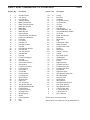
PART LIST—Model No. PFTL33105.0 R0805A
Key No. Qty. Description Key No. Qty. Description
1 2 Foot Rail Cover
2 25 3/4” Screw
3 1 Left Foot Rail
4 8 Foot Rail Screw
5 2 Motor Tension Bolt
6 2 Motor Tension Washer
7 1 Motor Star Washer
8 2 Motor Bolt
9 1 Drive Motor
10 1 Motor Bracket
11 7 Ground Screw
12 2 Power Bracket Star Washer
13 1 Power Cord Assembly
14 1 Filter Wire
15 2 Fan Screw
16 1 Console Fan
17 4 Handrail Endcap
18 2 Handrail
19 4 Handrail Star Washer
20 4 Handrail Bolt
21 2 1/4” Star Washer
22 2 Console Bolt
23 1 Key/Clip
24 1 Frame Pivot Spacer
25 1 Console
26 1 Console Base
27 2 Sliver Ground Screw
28 1 Upright Wire
29 1 Latch Pin Assembly
30 1 Latch Housing
31 1 Left Upright
32 2 Frame Bolt
33 2 Frame Washer
34
2
Frame Spacer
35 2 Base Endcap
36 1 Right Upright
37 4
Base Pad
38 13 3/4” Tek Screw
39 4 Upright Star Washer
40
6
Upright Bolt/Wheel Bolt
41 2 Caution Decal
42 1 Pulse Bar Bracket
43
1 Warning Decal
44
4
Wheel Spacer
45 2 Wheel
46 1 Pulley/Flywheel
47
4
Nut
48 1 Base
49 2 Clamp
50 1 Belly Pan
51 1 Controller
52 2 Lift Frame Washer
53 2 Lift Frame Bolt
54 5 3/8” Nut
55 1 Lift Motor
56 1 Stop Bracket
57 1 Incline Motor Bolt, Top
58 1 Incline Motor Bolt, Bottom
59 1 Lift Frame
60 2 Motor Tension Nut
61 1 Motor Belt
62 1 Reed Switch
63 1 Clip
64 1 Front Roller/ Pulley
65 1 Motor Pivot Bolt
66 2 Platform Bolt, Front
67 1 Magnet
68 2 Belt Guide
69 4 Isolator Fastener
70 2 Isolator
71 4 Belt Guide Screw
72 1 Walking Belt
73 1 Walking Platform
74 1 Frame
75 1 Right Foot Rail
76 2 Platform Nut, Rear
77 2 Platform Nut, Front
78 2 Platform Bolt, Rear
79 1 Rear Roller
80 1 Right Rear Foot
81 2 Rear Roller Star Washer
82
2
Rear Roller Bolt
83 1 Left Rear Foot
84 1 Ground Wire
85 1
Allen Wrench
86 1 Console Warning Decal
87 1 5/32” Allen Wrench
88
2
Rear Roller Bracket
# 1 4” Black Wire, M/F
# 1 8” Green Wire, F/R
#
1 4” Blue Wire, 2F
#
1
User’s Manual
#These parts are not illustrated
Specifications are subject to change without notice.
Page is loading ...
Page is loading ...
-
 1
1
-
 2
2
-
 3
3
-
 4
4
-
 5
5
-
 6
6
-
 7
7
-
 8
8
-
 9
9
-
 10
10
-
 11
11
-
 12
12
-
 13
13
-
 14
14
-
 15
15
-
 16
16
-
 17
17
-
 18
18
-
 19
19
-
 20
20
-
 21
21
-
 22
22


ProForm 495Pi PFTL33105.0 User manual
- Category
- Treadmills
- Type
- User manual
- This manual is also suitable for
Ask a question and I''ll find the answer in the document
Finding information in a document is now easier with AI
Related papers
-
ProForm PFTL31404.1 User manual
-
-
-
-
-
-
-
-
-
Other documents
-
Pro-Form 705 CST User manual
-
-
-
-
Weslo 30551.1 User manual
-
-
-
Weslo Cadence S6 Treadmill User manual
-
-