
¨
USERÕS MANUAL
Model No. HRSY23080
Serial No.
The serial number is found in the
location shown below. Write the
serial number in the space above.
CAUTION
Read all precautions and instruc-
tions in this manual before using
this equipment. Save this manu-
al for future reference.
Serial
Number
Decal
PATENT PENDING
QUESTIONS?
As a manufacturer, we are
committed to providing complete
customer satisfaction. If you
have questions, or if there are
missing or damaged parts, we
will guarantee complete satisfac-
tion through direct assistance
from our factory.
TO AVOID UNNECESSARY
DELAYS, PLEASE CALL DIRECT
TO OUR TOLL-FREE CUSTOMER
HOT LINE. The trained techni-
cians on our customer hot line
will provide immediate assis-
tance, free of charge to you.
CUSTOMER HOT LINE:
1-800-999-3756
Mon.ÐFri., 6 a.m.Ð6 p.m. MST

2
Important Precautions . . . . . . . . . . . . . . . . . . . . . . . . . . . . . . . . . . . . . . . . . . . . . . . . . . . . . . . . . . . . . . . . . . . 2
Before You Begin . . . . . . . . . . . . . . . . . . . . . . . . . . . . . . . . . . . . . . . . . . . . . . . . . . . . . . . . . . . . . . . . . . . . . . 3
Assembly . . . . . . . . . . . . . . . . . . . . . . . . . . . . . . . . . . . . . . . . . . . . . . . . . . . . . . . . . . . . . . . . . . . . . . . . . . . . 4
Cable Diagram . . . . . . . . . . . . . . . . . . . . . . . . . . . . . . . . . . . . . . . . . . . . . . . . . . . . . . . . . . . . . . . . . . . . . . . 19
Adjustment . . . . . . . . . . . . . . . . . . . . . . . . . . . . . . . . . . . . . . . . . . . . . . . . . . . . . . . . . . . . . . . . . . . . . . . . . . 20
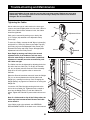
Weight Resistance Chart . . . . . . . . . . . . . . . . . . . . . . . . . . . . . . . . . . . . . . . . . . . . . . . . . . . . . . . . . . . . . . . . 22
Trouble-shooting and Maintenance . . . . . . . . . . . . . . . . . . . . . . . . . . . . . . . . . . . . . . . . . . . . . . . . . . . . . . . . 23
Ordering Replacement Parts . . . . . . . . . . . . . . . . . . . . . . . . . . . . . . . . . . . . . . . . . . . . . . . . . . . . . . Back Cover
Limited Warranty . . . . . . . . . . . . . . . . . . . . . . . . . . . . . . . . . . . . . . . . . . . . . . . . . . . . . . . . . . . . . . . Back Cover
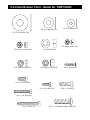
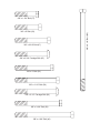
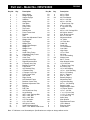
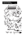
Note: A PART LIST/EXPLODED DRAWING and a PART IDENTIFICATION CHART are attached to the center of
this manual. Remove the PART LIST/EXPLODED DRAWING and the PART IDENTIFICATION CHART before
beginning assembly.
WARNING: Before beginning this or any exercise program, consult your physician. This is especially
important for persons over the age of 35 or persons with pre-existing health problems. Read all
instructions before using. ICON assumes no responsibility for personal injury or property damage
sustained by or through the use of this product.
Table of Contents
Important Precautions
1. It is the responsibility of the owner to ensure
that all users of the home gym system are
adequately informed of all precautions.
2. Read all instructions in this manual and in
the accompanying literature before using the
home gym system.
3. If you feel pain or dizziness at any time while
exercising, stop immediately and begin cool-
ing down.
4. Use the home gym system only on a level
surface. Cover the floor or carpet beneath the
home gym system for protection.
5. Inspect and tighten all parts often. Replace
any worn parts immediately.
6. Make sure the cables remain on the pulleys
at all times. If the cables bind while you are
exercising, stop immediately and make sure
the cables are on all of the pulleys.
7. Always stand on a foot plate when perform-
ing an exercise that could cause the home
gym system to tip.
8. Keep hands and feet away from moving parts.
9. Keep children under the age of 12 and pets
away from the home gym system at all times.
10. The home gym system is designed to be
used by only one person at a time.
11. Always wear athletic shoes for foot protec-
tion when exercising.
12. Never release the press arms, butterfly arms,
leg lever, lat bar or ab strap while weights are
raised. The weights will fall with great force.
13. Always disconnect the lat bar or ab strap
from the home gym system when performing
an exercise that does not use these attach-
ments.
14. The home gym system is intended for home
use only. Do not use the home gym system in
a commercial, rental or institutional setting.
15. WARNING: Never use the home gym system
without having both shrouds attached.
16. Always set the butterfly arms in the storage
position when you are using the press arms.
Likewise, store the press arms when you are
using the butterfly arms.
To reduce the risk of serious injury, read the following important
precautions before using the home gym system.
WARNING:

3
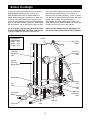
ASSEMBLED
DIMENSIONS:
Height: 81 in.
Width: 54 in.
Length: 67 in.
Low Pulley
Station
Foot Plate
Leg
Lever
Butterfly
Arm
Press Arms
Shroud
Covering
Weight Stack
Press Arm
Adjustment
Cam
Seat
Backrest
Thank you for selecting the innovative and versatile
HEALTHRIDER
¨
230 Home Gym System. The
HEALTHRIDER
¨
230 offers a unique selection of
weight stations designed to develop every major mus-
cle group of the body. Whether your goal is to tone
your body, build dramatic muscle size and strength or
improve your cardiovascular system, the HEALTHRID-
ER
¨
230 makes it easy to achieve the results you want.
For your benefit, read this manual carefully before
using the HEALTHRIDER
¨
230 Home Gym System.
If you have additional questions, please call our
Customer Service Department toll-free at 1-800-999-
3756, Monday through Friday, 6 a.m. until 6 p.m.
Mountain Time (excluding holidays). To help us assist
you, please note the product model number and serial
number before calling. The model number is
HRSY23080. The serial number can be found on a
decal attached to the HEALTHRIDER
¨
230 Home Gym
System (see the front cover of this manual).
Please use the drawing below to familiarize your-
self with the major parts and how they fit together.
Before You Begin
Weight Stack
Backrest
Adjustment
Knob
Press Arm
Adjustment
Knob
Adjustment
Disc
High Pulley
Station
Lat Bar

4
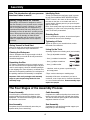
Note: This introduction will save you more
time than it takes to read it!
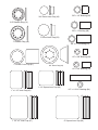
Identifying Parts
To help you identify the small parts used in assem-
bly, we have included a PART IDENTIFICATION
CHART located in the center of this manual. Place
the chart on the floor or work table and use it to
quickly identify different parts as you open the pack-
ages for each step.
Note: Some small parts may have been pre-attached
for shipping. If a part is not in the parts bag, check to
see if it has been pre-attached.
Orienting Parts
As you assemble this product, be sure that all parts
are oriented as shown in the drawings.
Tightening of Parts
Tighten all parts as you assemble them, unless
instructed to do otherwise.
Lining Up the Tools
Assembly requires the following tools (not included):
¥ Two (2) adjustable wrenches
¥ One (1) standard screwdriver
¥ One (1) phillips screwdriver
¥ One (1) rubber mallet
¥ Lubricant, such as grease or petroleum jelly,
and soapy water
¥ Tape, such as clear tape or masking tape
Assembly will be more convenient if you have a
socket set, a set of open-end or closed-end wrenches
or a set of ratchet wrenches. Some assembly steps
require two people.
Giving Yourself a Good Start
Before you begin the assembly process itself, take
the time to complete the steps outlined here.
Clearing the Workspace
Clear a workspace that is large enough to hold all
parts and allow you to walk all the way around the
assembled equipment.
Unpacking the Box
To make the assembly process as smooth as possi-
ble, we have broken it into separate stages. All parts
used in each stage are found in individual packages
in the shipping box. Place all parts in a cleared area
and remove the packing materials. Do not dispose of
the packing materials until assembly is completed.
Important: Wait until you begin each assembly
stage to open the parts bag labeled for that
assembly stage.
Assembly
Making Things Easier for Yourself
Everything in this manual is designed to ensure
that the assembly of our products can be complet-
ed successfully by anyone. However, it is impor-
tant to recognize that your new equipment is a
sophisticated product with many small parts. The
assembly process will take timeÑpossibly several
hours. Most people find that by setting aside plen-
ty of time, and by deciding to make the task
enjoyable, assembly will go smoothly. You may
want to complete the process over a couple of
evenings.
The Four Stages of the Assembly Process
Frame Assembly
You will begin by assembling the base and the
upright frames that serve as the skeleton of the
equipment. The seat and all moving parts will later
be attached to the frame.
Arm Assembly
Completes the press and butterfly arms that you
operate while you are exercising.
Cable Assembly
Completes the cables and pulleys that connect the
moving arms with each other and with the weights.
This ties the different parts together and makes the
equipment function as a unit.
Seat Assembly
Completes the seat and backrest that support your
body while you are exercising.

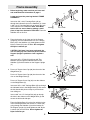
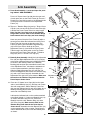
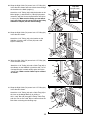
1. Before beginning, make sure that you have read
and understood the information on page 4.
Locate and open the parts bag labeled ÒFRAME
ASSEMBLY.Ó
Insert four 3/8Ó x 2 3/4Ó Carriage Bolts (45) up
through the indicated holes in the Stabilizer (4). Insert
a 3/8Ó x 3 1/2Ó Carriage Bolt (62) up through the hole
in the sidearm on the Stabilizer. Note: If the Bolts
tend to fall out, secure them by putting a small
piece of tape over the head of each Bolt. Place the
Stabilizer flat on the floor.
1
2. Place the bracket on the lower end of the Support
Upright (3) over the indicated 3/8Ó x 2 3/4Ó Carriage
Bolts (45) in the Stabilizer (4). Hand tighten two 3/8Ó
Nylon Locknuts (50) onto the Bolts. Do not tighten
the Nylon Locknuts yet.
CAUTION: Until step 3 has been performed, the
unit can easily tip over. Have one person hold the
Support Upright in position or lean it against a
wall.
Insert two 3/8Ó x 3Ó Bolts (53) with two 3/8Ó Flat
Washers (55) through the indicated holes in the
Stabilizer (4) and the bracket on the Support Upright
(3).
3. Press a 2Ó Square Inner Cap (28) into the end of the
Weight Base (5).
Press a 2Ó Square Inner Cap (28) into the end of the
riser on the Weight Base (5).
Press a 2Ó Square Cover Cap (33) onto the sidearm
on the Weight Base (5).
Insert two 3/8Ó x 2 3/4Ó Carriage Bolts (45) up through
the indicated holes in the Weight Base (5) and secure
the bolt heads with pieces of tape to prevent them
from falling out.
Insert a 3/8Ó x 3 1/2Ó Carriage Bolt (62) up through
the hole in the sidearm on the Weight Base (5) and
secure the bolt head with tape.
Place the Weight Base (5) on the floor with the holes
in the mounting bracket over the 3/8Ó x 3Ó Bolts (53)
going through the Stabilizer (4) and the bracket on
the Support Upright (3). Hand tighten two 3/8Ó Nylon
Locknuts (50) onto the Bolts. Do not tighten the
Nylon Locknuts yet.
2
3
5
Frame Assembly
45
4
62
45
53
55
45
4
53
55
Bracket
3
50
50
5
45
3
50
28
53
28
62
33
4

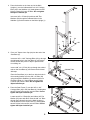
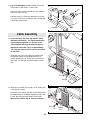
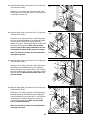
4. Place the bracket on the lower end of the Main
Upright (1) over the indicated 3/8Ó x 2 3/4Ó Carriage
Bolts (45) in the Stabilizer (4). Hand tighten two 3/8Ó
Nylon Locknuts (50) onto the Bolts. Do not tighten
the Nylon Locknuts yet.
Insert two 3/8Ó x 3Ó Bolts (53) with two 3/8Ó Flat
Washers (55) through the indicated holes in the
Stabilizer (4) and the bracket on the Main Upright (1).
4
6
5. Press a 2Ó Square Inner Cap (28) into the end of the
Seat Base (6).
Insert two 3/8Ó x 2 3/4Ó Carriage Bolts (45) up through
the indicated holes in the Seat Base (6) and secure
the bolt heads with pieces of tape to prevent them
from falling out.
Insert a 3/8Ó x 3 1/2Ó Bolt (56) up through the welded
tube on the Seat Base (6) and secure the bolt head
with tape.
Place the Seat Base (6) on the floor with the holes in
the mounting bracket over the 3/8Ó x 3Ó Bolts (53)
going through the Stabilizer (4) and the bracket on
the Main Upright (1). Hand tighten two 3/8Ó Nylon
Locknuts (50) onto the Bolts. Do not tighten the
Nylon Locknuts yet.
5
50
53
55
50
53
55
4
1
1
4
45
2845
56
6
53
50
6. Place the Seat Frame (7) onto the 3/8Ó x 2 3/4Ó
Carriage Bolts (45) in the Seat Base (6). Hand tighten
two 3/8Ó Nylon Locknuts (50) onto the Bolts. Do not
tighten the Nylon Locknuts yet.
Locate two 3/8Ó x 3Ó Bolts (53) and slide a 3/8Ó Flat
Washer (55) onto each Bolt. Insert the 3/8Ó x 3Ó Bolts
through the indicated holes in the Main Upright (1)
and the bracket on the Seat Frame (7). Hand tighten
two 3/8Ó Nylon Locknuts (50) onto the Bolts. Do not
tighten the Nylon Locknuts yet.
6
45
6
50
55
50
7
50
Welded Tube
53
1

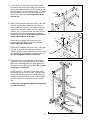
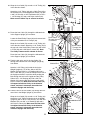
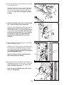
9. Place the bracket on the lower end of the Weight
Upright (2) over the indicated 3/8Ó x 2 3/4Ó Carriage
Bolts (45) in the Weight Base (5). Hand tighten two
3/8Ó Nylon Locknuts (50) onto the Bolts. Do not tight-
en the Nylon Locknuts yet.
Locate two 3/8Ó x 1 3/4Ó Bolts (57) and slide a 3/8Ó
Flat Washer (55) onto each of them. Insert the Bolts
through the indicated holes in the Weight Upright (2)
and then through the bracket on the Support Upright
(3). Secure the Bolts with two 3/8Ó Nylon Locknuts
(50).
Go back and fully tighten all Nylon Locknuts used
in steps 2 through 9.
9
7
7. Locate two 3/8Ó x 4 3/4Ó Bolts (46) and slide a 3/8Ó
Flat Washer (55) onto each of them. Insert the Bolts
through the indicated holes in the Top Frame (9) and
then through the holes in the Main Upright (1). Slide a
3/8Ó Flat Washer onto each Bolt and secure it with a
3/8Ó Nylon Locknut (50). Do not tighten the Nylon
Locknut yet.
7
8. Slide a 3/8Ó Flat Washer (55) onto a 3/8Ó x 4 3/4Ó Bolt
(46) and push the Bolt through the Top Frame (9).
Push the Bolt into the hole in the Support Upright (3)
until the tip of the Bolt is visible inside the Upright.
Slide the 1/2Ó x 1 13/16Ó Bushing (84) down into the
Upright and push the Bolt all the way through the
Bushing and the Upright. Note: Make sure you donÕt
drop the Bushing into the Upright!
Slide a 3/8Ó Flat Washer (55) onto the Bolt and
secure it with a 3/8Ó Nylon Locknut (50). Do not
tighten the Nylon Locknut yet.
Slide a 3/8Ó Flat Washer (55) onto a 3/8Ó x 2 3/4Ó Bolt
(47) and insert the Bolt through the hole in the
Support Upright (3) and the bracket on the Top Frame
(9). Hand tighten a 3/8Ó Nylon Locknut (50) onto the
Bolt. Do not tighten the Nylon Locknut yet.
8
45
5
50
3
50
50
55
2
50
57
55
50
Bracket
Bracket
1
9
55
46
28
9
50
55
55
1
55
47
3
84
50
46

8
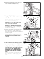
12. Attach the upper ends of the Weight Guides (15) to
the welded bracket underneath the Weight Upright (2)
with two 3/8Ó x 1 3/4Ó Bolts (57) and two 3/8Ó Nylon
Locknuts (50). Tighten, but do not overtighten, the
Nylon Locknuts.
12
11. Slide a 3/8Ó Flat Washer (55) and a 5/8Ó x 1/2Ó
Bushing (85) onto a 3/8Ó x 2 3/4Ó Bolt (47). Line up
the hole in the indicated Weight Guide (15) with the
hole in the Weight Base (5). Slide the 3/8Ó x 2 3/4Ó
Bolt through the Weight Guide and the Weight Base.
Slide a 5/8Ó x 1/2Ó Bushing (85) onto the Bolt. Secure
the Bolt with a 3/8Ó Flat Washer (55) and a 3/8Ó Nylon
Locknut (50).
11
85
85
47
5
55
55
15
57
50
2
50
15
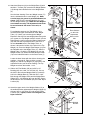
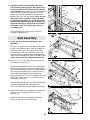
10. Attach two Bumpers (40) to the Weight Base (5) with
two #8 x 1Ó Screws (78). Insert the two Weight Guides
(15) through the indicated holes in the Weight Base
(5).
See the inset drawing. Press two Weight Inserts (77)
into the indicated holes in each Weight (21). Make
sure the large pin groove is pointed downward, as
shown. Slide all of the included Weights (21) onto
the two Weight Guides (15). Make sure the Weights
are oriented correctly. The adjustment holes must
be turned towards the center of the unit, as
shown.
For packaging purposes, the Top Weight (16) is
mounted in the upper threaded hole in the Weight
Tube (17). Unless you have bought the Weight
Expansion Set with five extra weight plates along with
your system, the Top Weight must be moved. Use the
Allen Wrench (100) to loosen the Button Head Screw
(52) and slide the Top Weight down to the lower of
the two threaded holes in the Weight Tube, as
shown. Lubricate the insides of the holes in the Top
Weight (16). Press the Weight Tube Bumper (18) into
the indicated end of the Weight Tube (17). Slide the
Weight Tube (17) with the Top Weight (16) onto the
Weight Guides (15). Attach the Allen Wrench Holder
(79) to the indicated location on the Seat Frame (7)
Locate the decal sheet with the stickers showing the
numbers 1 through 15. Place a sticker on each
Weight (21) and the Top Weight (16) right next to the
adjustment holes (see the inset drawing). The Top
Weight must have the number 1 on it.
10
5
15
16
52
17
18
100
7
79
2
78
40
21
77
21
Large Pin
Groove
Number
Decal
Adjustment
Holes on this
side
Place Stickers
on this side
Lubricate
Welded
Bracket

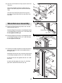
14. Tap two 1Ó Retainer Rings (32) and a 1Ó Round Cover
Cap (81) onto one end of the Press Frame Tube (34).
Lubricate the Press Frame Tube in its entire length.
Note: Use the Cover Cap to tap on the Retainer
Rings. Make sure the teeth on the Retainer Rings
bend towards the Cover Cap (see inset drawing).
Have one person lift up the Press Frame (8) while a
second person slides the indicated end of the Press
Frame Tube (34) through the bracket on the Top
Frame (9) and the pre-assembled Large Bushings
(44) in the Press Frame. Hold up the Press
Adjustment Frame (14) and slide the Press Frame
Tube through it and the bracket on the Top Frame.
Secure the Press Frame Tube with two 1Ó Retainer
Rings (32) and a 1Ó Round Cover Cap (81).
9
16. Press two 2Ó Square Inner Caps (28) into the open
ends of each Butterfly Arm (10). Wet the end of each
Arm with soapy water. Slide a Butterfly Foam Pad
(29) onto the indicated end of each Arm. Make sure a
Butterfly Bushing (88) has been pre-assembled on
each side of the Butterfly Arms.
Lubricate the indicated rod on the crossbar attached
to the Main Upright (1). Orient one Butterfly Arm (10)
as shown and slide it onto the rod. Secure the
Butterfly Arm with a 3/4Ó Retainer Ring (31) and a
3/4Ó Dome Cap (82). Make sure the teeth on the
Retainer Ring bend towards the Dome Cap as
shown above. Assemble the other Butterfly Arm (10)
on the opposite side of the crossbar. Follow the pro-
cedure described above, but orient the Butterfly Arm
as shown.
16
13. Press Arm AssemblyÑLocate and open the parts
bag labeled ÒARM ASSEMBLY.Ó
Press a 2Ó Square Inner Cap (28) into the open end
of each press arm on the Press Frame (8). Press a 1Ó
Round Inner Cap (58) into each of the indicated holes
on the press arms. Locate the Press Adjustment
Frame (14).
13
28
14
58
32
14
81
32
9
81
14
8
34
44
28
1
29
10
10
31
82
88
28
15. Butterfly Arm Assembly. Identify the Left Adjustment
Disc (26) and Right Adjustment Disc (27) by looking
at the three adjustment holes and orienting the Discs
as shown in the drawing. Make sure a Butterfly
Bushing (88) has been pre-assembled on each side
of the Adjustment Discs. Lubricate the indicated rod
on the crossbar attached to the Main Upright (1).
Slide the Right Adjustment Disc (27) onto the rod.
Secure the Adjustment Disc with a 3/4Ó Retainer Ring
(31) and a 3/4Ó Dome Cap (82). Assemble the Left
Adjustment Disc (26) in the same manner. Make sure
the teeth on the Retainer Ring bend towards the
Dome Cap as shown above.
15
82
31
26
Adjustment
Holes
Adjustment Holes
Crossbar
27
58
28
8
Arm Assembly
28
Teeth
34
81
32
88
Lubricate
Lubricate
Lubricate

17
17. Leg Lever Assembly. Attach a Bumper (40) to the
Seat Frame (7) with a #8 x 1Ó Screw (78).
Press a 2Ó Square Inner Cap (28) into the indicated
end of the Leg Lever (41).
Lubricate a 3/8Ó x 3Ó Bolt (53). Attach the Leg Lever
(41) to the Seat Frame (7) with the 3/8Ó x 3Ó Bolt and
a 3/8Ó Nylon Jamnut (63).
10
18. Locate and open the parts bag labeled ÒCable
Assembly and Pulleys.Ó For Cable identification
and routing during steps 18Ñ39, refer to the
Cable Diagram and Cable ID Chart on page 19.
Identify the Low Cable (72). It is approximately
176Ó long and it has a ball on one end and a bolt
on the other.
Route the end of the Low Cable (72) with the ball
through the bracket on the Weight Base (5) as
shown. Attach the 3 1/2Ó Pulley (24) to the bracket
with a 3/8Ó x 2Ó Bolt (54) and a 3/8Ó Nylon Locknut
(50).
18
40
78
53
7
Lubricate
41
28
63
24
72
50
54
Cable Assembly
5
Bracket
19. Wrap the Low Cable (72) around a 3 1/2Ó Pulley (24)
in the direction shown.
Attach the 3 1/2Ó Pulley (24) and a Cable Trap (25) to
the welded tube on the Weight Upright (2) with a 3/8Ó
x 3 3/4Ó Bolt (59) and a 3/8Ó Nylon Locknut (50).
Make sure the Cable Trap is oriented as shown.
19
2
59
72
50
25
24
Welded
Tube

11
23. Feed the end of the Low Cable (72) through the indi-
cated slot in the Weight Upright (2) from above.
Wrap the Low Cable (72) around a 3 1/2Ó Pulley (24).
Attach the 3 1/2Ó Pulley inside the slot in the Weight
Upright (2) with a 3/8Ó x 2 3/4Ó Bolt (47), two 3/8Ó Flat
Washers (55), two 5/8Ó x 1/2Ó Bushings (85) and a
3/8Ó Nylon Locknut (50). Make sure the Low Cable
is wrapped around the Pulley in the direction
shown, and that it is between the welded rod
inside the Upright and the Pulley.
23
22. Feed the bolt at the end of the Low Cable (72)
through the indicated slot in the Weight Upright (2)
from below.
Attach a 3 1/2Ó Pulley (24) inside the slot in the
Weight Upright (2). To do this, slide a 3/8Ó Flat
Washer (55) and a 5/8Ó x 1/2Ó Bushing (85) onto a
3/8Ó x 2 3/4Ó Bolt (47). Insert the Pulley into the slot in
the Upright and hold it in position while pushing the
Bolt through the hole in the Upright and the Pulley.
Slide a 5/8Ó x 1/2Ó Bushing (85) and a 3/8Ó Flat
Washer (55) onto the Bolt and secure it with a 3/8Ó
Nylon Locknut (50). Make sure the Low Cable (72)
is wrapped around the Pulley in the direction
shown, and that it is between the welded rod
inside the Upright and the Pulley.
22
21. Route the Low Cable (72) through the indicated slot
in the Support Upright (3) from above.
Locate the Small Pulley Frame (22) and remove both
of the pre-assembled 3 1/2Ó Pulleys (24).
Wrap the Low Cable (72) around a 3 1/2Ó Pulley (24)
in the direction shown. Attach the 3 1/2Ó Pulley (24) to
the top half of the Small Pulley Frame (22) with a 3/8Ó
x 2Ó Bolt (54) and a 3/8Ó Nylon Locknut (50). Note:
The Pulley Frame must be oriented as shown.
Route the Low Cable (72) through the indicated slot
in the Support Upright (3) from below.
21
24
54
72
3
22
Route Cable
Through Slot
From Below
50
47
2
24
85
55
50
72
Bolt
20. Wrap the Low Cable (72) around a 3 1/2Ó Pulley (24)
in the direction shown.
Attach the 3 1/2Ó Pulley (24) and a Cable Trap (25) to
the bracket on the Press Adjustment Frame (14) with
a 3/8Ó x 3Ó Bolt (53), a 3/8Ó Flat Washer (55), a 5/8Ó x
1 1/4Ó Bushing (91) and a 3/8Ó Nylon Jamnut (63).
Make sure the Cable Trap is oriented as shown.
20
14
24
91
25
63
53
55
72
55
85
47
2
24
85
55
50
72
Bolt
55
85
Route Cable
Through Slot
From Above
Welded Rod
Welded Rod

12
26. Route the end of the High Cable (73) with the loop
through the bracket on the Main Upright (1) from
above. Route the High Cable over a 3 1/2Ó Pulley (24)
in the direction shown.
Slide the 3 1/2Ó Pulley (24) into the bracket on the
Main Upright (1). Slide a 3/8Ó x 3Ó Bolt (53) through
the bracket and the Pulley, but do not mount a
Locknut yet.
26
1
73
53
24
Bracket
27. Locate the Adjustable Pulley Frame (23) and remove
the 3 1/2Ó Pulleys (24) and Cable Traps (25).
Wrap the High Cable (73) around a 3 1/2Ó Pulley (24)
in the direction shown. Attach the 3 1/2Ó Pulley and a
Cable Trap (25) to the top half of the Adjustable
Pulley Frame (23) with a 3/8Ó x 2Ó Bolt (54) and a 3/8Ó
Nylon Locknut (50). Note: The Pulley must be
attached to the upper of the three adjustment
holes. Make sure the Cable Trap is oriented as
shown.
Route the end of the High Cable (73) with the loop
through the bracket on the Main Upright (1) from
below.
27
23
50
25
1
54
24
73
25. Identify the High Cable (73). It is approximately
340Ó long and it has a ball on one end and a loop
on the other.
Route the end of the High Cable (73) with the loop
through the slot in the Main Upright (1).
Wrap the end of the High Cable (73) with the ball
around a 3 1/2Ó Pulley (24) as shown.
Attach the 3 1/2Ó Pulley (24) inside the slot in the
Main Upright (1) with a 3/8Ó x 3 3/4Ó Bolt (59), two
3/8Ó Flat Washers (55), two 5/8Ó x 1Ó Bushings (86)
and a 3/8Ó Nylon Locknut (50).
25
50
55
55
1
Slot
86
59
24
73
86
24. Thread the bolt at the end of the Low Cable (72) a
couple of turns into the Weight Tube (17).
24
72
Bolt
17
Bracket

13
29. Wrap the High Cable (73) around a 3 1/2Ó Pulley (24)
in the direction shown.
Attach the 3 1/2Ó Pulley (24) to the bracket on the
Stabilizer (4) with a 3/8Ó x 2Ó Bolt (54) and a 3/8Ó
Nylon Locknut (50).
29
28. Wrap the High Cable (73) around a 3 1/2Ó Pulley (24)
in the direction shown and route it back down through
the bracket on the Main Upright (1).
Attach the 3 1/2Ó Pulley (24) inside the bracket on the
Main Upright (1) with the 3/8Ó x 3Ó Bolt (53) that was
inserted in step 26. Secure the Bolt with a 3/8Ó Nylon
Locknut (50). Make sure the Pulley you are attach-
ing in this step is on the correct side of the Pulley
attached in step 26 (see the inset drawing).
28
50
1
73
53
4
54
24
73
50
30. Wrap the High Cable (73) around a 3 1/2Ó Pulley (24)
in the direction shown.
Attach the 3 1/2Ó Pulley (24) and a Cable Trap (25) to
the sidearm on the Stabilizer (4) with the 3/8Ó x 3 1/2Ó
Carriage Bolt (62, inserted earlier) and a 3/8Ó Nylon
Jamnut (63). Make sure the Cable Trap is oriented
as shown.
30
24
31. Wrap the High Cable (73) around a 3 1/2Ó Pulley (24)
in the direction shown.
Attach the 3 1/2Ó Pulley (24) and a Cable Trap (25) to
the riser on the Weight Base (5) by sliding a
3/8Ó x 4 3/4Ó Bolt (46) through the Pulley, Cable Trap
and riser. Do not use a 3/8Ó Nylon Locknut unless the
Bolt slides out during the following step.
31
Riser
25
24
5
73
46
Second Pulley
Top View
First Pulley
24
25
62
73
4
63
1
Bracket

14
33. Wrap the High Cable (73) around a 3 1/2Ó Pulley (24)
in the direction shown.
Attach the 3 1/2Ó Pulley (24) and a Cable Trap (25) to
the riser on the Weight Base (5) by sliding the Cable
Trap and Pulley onto the 3/8Ó x 4 3/4Ó Bolt (46)
attached in step 31. Thread a 3/8Ó Nylon Locknut (50)
onto the Bolt and tighten it. Make sure the Cable
Traps for both of the Pulleys attached to the riser
are oriented as shown in this step and in step 31.
Note: For the sake of clarity, drawing 33A shows
some parts removed.
34. Wrap the High Cable (73) around a 3 1/2Ó Pulley (24)
in the direction shown.
Attach the 3 1/2Ó Pulley (24) and a Cable Trap (25) to
the sidearm on the Weight Base (5) by sliding the
Pulley and Cable Trap onto the 3/8Ó x 3 1/2Ó Carriage
Bolt (62) inserted earlier. Tighten a 3/8Ó Nylon Jamnut
(63) onto the Bolt. Make sure the Cable Trap is ori-
ented as shown.
33A B
34
32. Wrap the High Cable (73) around a 3 1/2Ó Pulley (24)
in the direction shown.
Attach the 3 1/2Ó Pulley (24) to the lower half of the
Small Pulley Frame (22) with a 3/8Ó x 2Ó Bolt (54) and
a 3/8Ó Nylon Locknut (50).
32
50
54
24
73
Mount
Pulley
Here
50
46
62
5
73
25
24
63
22
24
25
Riser
5
35. Wrap the High Cable (73) around a 3 1/2Ó Pulley (24)
in the direction shown.
Attach the 3 1/2Ó Pulley (24) and a Cable Trap (25) to
the welded tube on the Seat Base (6) by sliding the
Pulley and Cable Trap onto the 3/8Ó x 3 1/2Ó Bolt (56)
inserted earlier. Thread a 3/8Ó Nylon Locknut (50)
onto the Bolt and tighten it. Make sure the Cable
Trap is oriented as shown.
Note: For the sake of clarity, drawing 35A shows
some parts removed.
73
35A B
73
Mount
Pulley
Here
50
56
24
25
Welded
Tube
6

15
36. Route the High Cable (73) through the slot in the leg
of the Seat Frame (7).
Attach the closed loop at the end of the High Cable
(73) to the Leg Lever (41) with a 3/8Ó x 2 3/4Ó Bolt
(47), two 3/8Ó Flat Washers (55) and a 3/8Ó Nylon
Locknut (50). Note: Do not overtighten the Nylon
Locknut.
36
41
7
55
55
50
47
73
Slot
37. Identify the Butterfly Cable (92). It is approximate-
ly 61Ó long and it has a loop on both ends.
Attach one end of the Butterfly Cable (92) to the Left
Adjustment Disc (26) with a 5/16Ó x 1Ó Bolt (87), a
3/8Ó Flat Washer (55), a 1/2Ó x 3/8Ó Bushing (83) and
a 5/16Ó Nylon Locknut (64). Note: The loop on the
Cable must wrap around the 1/2Ó x 3/8Ó Bushing.
For the sake of clarity, some parts have been
removed and the Adjustment Disc is shown
exploded.
37
83
64
55
87
26
92
38. Wrap the Butterfly Cable (92) around a 3 1/2Ó Pulley
(24) in the direction shown.
Attach the 3 1/2Ó Pulley (24) and a Cable Trap (25) to
the lower half of the Adjustable Pulley Frame (23)
with a 3/8Ó x 2Ó Bolt (54) and a 3/8Ó Nylon Locknut
(50). The Pulley must be attached to the middle of
the three adjustment holes.
Note: For the sake of clarity, some parts have
been removed from the drawing.
38
50
54
25
23
24
92
39. Attach the free end of the Butterfly Cable (92) to the
Right Adjustment Disc (27) with a 5/16Ó x 1Ó Bolt (87),
a 3/8Ó Flat Washer (55), a 1/2Ó x 3/8Ó Bushing (83)
and a 5/16Ó Nylon Locknut (64).
Note: The loop on the Cable must wrap around
the 1/2Ó x 3/8Ó Bushing.
39
92
83
64
27
55
87

16
40
21
19
17
89
48
68
40. Important: Follow all three Cables from end to
end and make sure they rest in the grooves of all
Pulleys and that both the Cables and the Pulleys
move smoothly. Attach the bolt at the end of the Low
Cable (72), the 1/2Ó Plain Nut (68), the 1 1/2Ó Flat
Washer (48) and the Adjustment Tube (89) to the
Weight Tube (17) in the order shown. Note: The bolt
at the end of the Low Cable is one of the means
for tightening the Cables (72, 73 and 92). Thread
the bolt into the Weight Tube until all Cables are
tight and rest firmly in the grooves of all Pulleys.
Then tighten the 1/2Ó Plain Nut (68) onto the 1
1/2Ó Washer (48).
Insert the Weight Pin (19) into one of the holes
between the Weights (21).
42
65
65
39
50
96
7
37
101
Welded Bushings
96
42. Press a 1Ó x 1 1/2Ó Inner Cap (96) into each end of
both Backrest Frames (37).
Identify the Right Backrest Frame (101) and the Left
Backrest Frame (37) by looking at the welded bush-
ings. Orient the Backrest Frames so the welded bush-
ings are facing the Seat Frame (7) and are on the
lower edge of the Backrest Frames. Attach the
Backrest Frames (37, 101) to the indicated hole in the
Seat Frame (7) with a 3/8Ó x 6 1/2Ó Bolt (65) and a
3/8Ó Nylon Locknut (50).
Attach the Backrest Frames (37) to the indicated hole
in the Backrest Adjustment Tube (39) with a
3/8Ó x 6 1/2Ó Bolt (65) and a 3/8Ó Nylon Locknut (50).
43
7
74
74
12
71
13
37
71
49
43. Attach the Backrest (12) to the Backrest Frames (37)
with four 1/4Ó x 2Ó Bolts (74) and four 1/4Ó Flat
Washers (71).
Attach the Seat (13) to the brackets on the Seat
Frame (7) with four 1/4 x 3/4Ó Bolts (49).
41
Bracket
47
7
39
51
38
98
50
41. Locate and open the parts bag labeled ÒSeat
Assembly.Ó
Press a 1 1/4Ó Square Inner Cap (98) into the indicat-
ed end of the Backrest Center Tube (38). Attach the
Backrest Center Tube to the bracket on the Seat
Frame (7) with a 3/8Ó x 2 3/4Ó Bolt (47) and a 3/8Ó
Nylon Locknut (50). Slide the Backrest Adjustment
Tube (39) onto the Backrest Center Tube (38). If nec-
essary, pull out the Short Adjustment Knob (51).
Seat Assembly
72

17
44. Press two 3/4Ó Round Inner Caps (43) into each Pad
Tube (42).
Insert one Pad Tube (42) into the Seat Frame (7).
Slide a Foam Roller (30) onto each end of the Pad
Tube.
Insert the other Pad Tube (42) into the Leg Lever
(41). Slide a Foam Roller (30) onto each end of the
Pad Tube.
44 43
43
30
30
42
42
30
30
43
43
7
41
Miscellaneous Assembly
47. Follow the procedure described in steps 45 and 46 to
attach the Left Shroud (35) on the opposite side of
the weight stack.
Attach both Shrouds (35, 36) to the end of the top bar
on the Weight Upright (2) with a 1/4Ó x 5/8Ó Bolt (80).
Tie the Shrouds (35, 36) together with four 1/4Ó x 5/8Ó
Bolts (80).
Go back and fully tighten all of the 1/4Ó x 5/8Ó Bolts
(80) used to attach both Shrouds (35, 36).
47
35
36
80
80
80
2
Top Bar
80
80
45. Identify the Right Shroud (36) which is the one that
does not have a slot in it.
Attach the Right Shroud (36) to the indicated brackets
on the Weight Base (5) with two 1/4Ó x 5/8Ó Bolts (80).
Do not tighten the Bolts yet.
45
80
36
80
5
Bracket
46. Attach the Right Shroud (36) to the indicated bracket
on the Weight Upright (2) with a 1/4Ó x 5/8Ó Bolt (80).
Do not tighten the Bolt yet.
46
36
80
2
Bracket

18
48
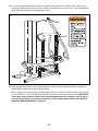
48. The decal shown below has been attached to the home gym system in the location shown. If the decal is
missing or illegible, please call our customer hotline at the number on the front cover to order a replacement
decal. Apply the new decal in the appropriate location.
49. Make sure that all parts have been properly tightened. The use of the remaining parts will be explained in
ADJUSTMENT, beginning on page 20 of this manual.
Before using the home gym system, pull each cable a few times to make sure that the cables move smooth-
ly over the pulleys. If one of the cables does not move smoothly, find and correct the problem. IMPORTANT:
If the cables are not properly installed, they may be damaged when heavy weight is used. If there is
any slack in the cables, you will need to remove the slack by tightening the cables. See TROUBLE-
SHOOTING AND MAINTENANCE on page 23.

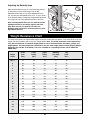
19
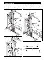
Cable Diagram
The Cable Diagrams below show the proper routing of the Butterfly Cable (92), the High Cable (73) and the Low
Cable (72). The numbers show the correct route for each Cable. Make sure the Cables are routed correctly,
that the Pulleys move smoothly and that the Cable Traps do not touch or bind the Cables. Incorrect
cable routing can damage the weight system.
Low Cable (72)
5
7
4
3
6
1
2
High Cable (73)
1
2
3
9
5
4
6
7
10
8
1
3
2
Butterfly Cable (92)
Cable ID Chart
92
73
72
11
12

20
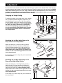
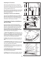
Attaching the Lat Bar, Ankle Strap or Ab
Strap to the High Pulley Station
Attach the Lat Bar (61) to the High Cable (73) with a
Cable Clip (69). For some exercises, the Chain (67)
should be attached between the Lat Bar and the High
Cable with two Cable Clips. Adjust the length of the
Chain between the Lat Bar and the High Cable so the
Lat Bar is in the correct starting position for the exer-
cise to be performed.
The Ab Strap (75) or Ankle Strap (99) can be attached in
the same manner.
75
69
69
67
99
61
73
Adjustment
Changing the Weight Setting
To change the setting of the weight stack, insert a Weight
Pin (19) under the desired Weight (21). Make sure you
insert the Weight Pin as far as it will go. The weight set-
ting of the weight stack can be changed from 10 pounds
to 150 pounds, in increments of 10 pounds. Note: Due to
the cables and pulleys, the amount of resistance at
each exercise station may vary from the weight set-
ting. Use the WEIGHT RESISTANCE CHART on page
22 to find the approximate amount of resistance at
each weight station.
21
19
The instructions below describe how each part of the home gym system can be adjusted. Refer to the exercise
guide accompanying this manual to see how the home gym system should be set up for each exercise. IMPOR-
TANT: When attaching the lat bar or ab strap, make sure that the attachments are in the correct starting
position for the exercise to be performed. If there is any slack in the cables or chain as an exercise is
performed, the effectiveness of the exercise will be reduced.
Attaching the Lat Bar, Ankle Strap or Ab
Strap to the Low Pulley Station
Attach the Lat Bar (61) to the Low Cable (72) with a
Cable Clip (69). For some exercises, the Chain (67)
should be attached between the Lat Bar and the Low
Cable with two Cable Clips. Adjust the length of the
Chain between the Lat Bar and the Low Cable so the
Lat Bar is in the correct starting position for the exer-
cise to be performed.
The Ankle Strap (99) or Ab Strap (75) can be attached in
the same manner.
72
67
75
61
69
69
99
Page is loading ...
Page is loading ...
Page is loading ...
Page is loading ...
Page is loading ...
Page is loading ...
Page is loading ...
Page is loading ...
Page is loading ...
-
 1
1
-
 2
2
-
 3
3
-
 4
4
-
 5
5
-
 6
6
-
 7
7
-
 8
8
-
 9
9
-
 10
10
-
 11
11
-
 12
12
-
 13
13
-
 14
14
-
 15
15
-
 16
16
-
 17
17
-
 18
18
-
 19
19
-
 20
20
-
 21
21
-
 22
22
-
 23
23
-
 24
24
-
 25
25
-
 26
26
-
 27
27
-
 28
28
-
 29
29


HealthRider HRSY2308 230 GYM SYSTEM User manual
- Type
- User manual
- This manual is also suitable for
Ask a question and I''ll find the answer in the document
Finding information in a document is now easier with AI
Related papers
Other documents
-
Weider WECCSY2983 User manual
-
-
-
ProForm PFSY74490 User manual
-
-
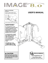 Image 8 User manual
-
-
-
Sears 831.159460 User manual
-
