ATEN VE814AT User manual
- Category
- Network switches
- Type
- User manual
This manual is also suitable for

VE814A
HDMI HDBaseT Extender
with Dual Output
User Manual

VE814A User Manual
ii
Compliance Statements
FEDERAL COMMUNICATIONS COMMISSION INTERFERENCE
STATEMENT
This equipment has been tested and found to comply with the limits for a Class
A digital device, pursuant to Part 15 of the FCC Rules. These limits are
designed to provide reasonable protection against harmful interference when
the equipment is operated in a commercial environment. This equipment
generates, uses, and can radiate radio frequency energy and, if not installed and
used in accordance with the instruction manual, may cause harmful
interference to radio communications. Operation of this equipment in a
residential area is likely to cause harmful interference in which case the user
will be required to correct the interference at his own expense.
The device complies with Part 15 of the FCC Rules. Operation is subject to the
following two conditions: (1) this device may not cause harmful interference,
and (2) this device must accept any interference received, including
interference that may cause undesired operation.
FCC Caution
Any changes or modifications not expressly approved by the party responsible
for compliance could void the user's authority to operate this equipment.
Warning
Operation of this equipment in a residential environment could cause radio
interference.
Achtung
Der Gebrauch dieses Geräts in Wohnumgebung kann Funkstörungen
verursachen.
Suggestion
Shield twisted pair (STP) cables must be used with the unit to ensure
compliance with FCC & CE standards.
KCC Statement

VE814A User Manual
iii
HDMI Trademark Statement
The terms HDMI, HDMI High-Definition Multimedia Interface, and the
HDMI Logo are trademarks or registered trademarks of HDMI Licensing
Administrator, Inc.
RoHS
This product is RoHS compliant.

VE814A User Manual
iv
User Information
Online Registration
Be sure to register your product at our online support center:
Telephone Support
For telephone support, call this number:
User Notice
All information, documentation, and specifications contained in this manual
are subject to change without prior notification by the manufacturer. The
manufacturer makes no representations or warranties, either expressed or
implied, with respect to the contents hereof and specifically disclaims any
warranties as to merchantability or fitness for any particular purpose. Any of
the manufacturer's software described in this manual is sold or licensed as is.
Should the programs prove defective following their purchase, the buyer (and
not the manufacturer, its distributor, or its dealer), assumes the entire cost of all
necessary servicing, repair and any incidental or consequential damages
resulting from any defect in the software.
The manufacturer of this system is not responsible for any radio and/or TV
interference caused by unauthorized modifications to this device. It is the
responsibility of the user to correct such interference.
The manufacturer is not responsible for any damage incurred in the operation
of this system if the correct operational voltage setting was not selected prior
to operation. PLEASE VERIFY THAT THE VOLTAGE SETTING IS
CORRECT BEFORE USE.
International http://eservice.aten.com
International 886-2-8692-6959
China 86-400-810-0-810
Japan 81-3-5615-5811
Korea 82-2-467-6789
North America 1-888-999-ATEN ext 4988
1-949-428-1111

VE814A User Manual
v
Product Information
For information about all ATEN products and how they can help you connect
without limits, visit ATEN on the Web or contact an ATEN Authorized
Reseller. Visit ATEN on the Web for a list of locations and telephone numbers:
International http://www.aten.com
North America http://www.aten-usa.com

VE814A User Manual
vi
Package Contents
Check to make sure that all the components are in working order. If you
encounter any problem, please contact your dealer.
VE814A Package Contents
1 VE814AT Transmitter
1 VE814AR Receiver
1 IR transmitter
1 IR receiver
2 RS-232 terminal blocks
2 power adapters
1 user instructions
VE814AT Package Contents
1 VE814AT Transmitter
1 RS-232 terminal block
1 power adapter
1 user instructions
VE814AR Package Contents
1 VE814AR Transmitter
1 RS-232 terminal block
1 power adapter
1 user instructions
Note: The included IR cables supports frequencies from 30 kHz to 56 kHz.

VE814A User Manual
vii
Table of Contents
Compliance Statements . . . . . . . . . . . . . . . . . . . . . . . . . . . . . . . . . . . . . . . ii
User Information . . . . . . . . . . . . . . . . . . . . . . . . . . . . . . . . . . . . . . . . . . . .iv
Online Registration . . . . . . . . . . . . . . . . . . . . . . . . . . . . . . . . . . . . . . . .iv
Telephone Support . . . . . . . . . . . . . . . . . . . . . . . . . . . . . . . . . . . . . . . .iv
User Notice . . . . . . . . . . . . . . . . . . . . . . . . . . . . . . . . . . . . . . . . . . . . . .iv
Product Information . . . . . . . . . . . . . . . . . . . . . . . . . . . . . . . . . . . . . . . . . . v
Package Contents . . . . . . . . . . . . . . . . . . . . . . . . . . . . . . . . . . . . . . . . . . .vi
VE814A Package Contents. . . . . . . . . . . . . . . . . . . . . . . . . . . . . . . . . .vi
VE814AT Package Contents . . . . . . . . . . . . . . . . . . . . . . . . . . . . . . . .vi
VE814AR Package Contents . . . . . . . . . . . . . . . . . . . . . . . . . . . . . . . .vi
Table of Contents . . . . . . . . . . . . . . . . . . . . . . . . . . . . . . . . . . . . . . . . . . vii
About this Manual . . . . . . . . . . . . . . . . . . . . . . . . . . . . . . . . . . . . . . . . . . .ix
Conventions . . . . . . . . . . . . . . . . . . . . . . . . . . . . . . . . . . . . . . . . . . . . . x
1. Introduction
Overview. . . . . . . . . . . . . . . . . . . . . . . . . . . . . . . . . . . . . . . . . . . . . . . . . . . 1
Features . . . . . . . . . . . . . . . . . . . . . . . . . . . . . . . . . . . . . . . . . . . . . . . . . . . 2
Planning the Installation . . . . . . . . . . . . . . . . . . . . . . . . . . . . . . . . . . . . . . . 3
Requirements . . . . . . . . . . . . . . . . . . . . . . . . . . . . . . . . . . . . . . . . . . . . 3
Considerations . . . . . . . . . . . . . . . . . . . . . . . . . . . . . . . . . . . . . . . . . . . 3
2. Hardware Setup
Components . . . . . . . . . . . . . . . . . . . . . . . . . . . . . . . . . . . . . . . . . . . . . . . . 5
VE814AT Front View. . . . . . . . . . . . . . . . . . . . . . . . . . . . . . . . . . . . . . . 5
VE814AT Rear View . . . . . . . . . . . . . . . . . . . . . . . . . . . . . . . . . . . . . . . 6
VE814AR Front View . . . . . . . . . . . . . . . . . . . . . . . . . . . . . . . . . . . . . . 7
VE814AR Rear View . . . . . . . . . . . . . . . . . . . . . . . . . . . . . . . . . . . . . . 8
LED Display . . . . . . . . . . . . . . . . . . . . . . . . . . . . . . . . . . . . . . . . . . . . . 9
Mounting the VE814A Unit . . . . . . . . . . . . . . . . . . . . . . . . . . . . . . . . . . . 10
Wall Mount . . . . . . . . . . . . . . . . . . . . . . . . . . . . . . . . . . . . . . . . . . . . . 10
Rack Mount. . . . . . . . . . . . . . . . . . . . . . . . . . . . . . . . . . . . . . . . . . . . . 10
Connecting the VE814A Unit . . . . . . . . . . . . . . . . . . . . . . . . . . . . . . . . . . 11
RS-232 Channel Transmission . . . . . . . . . . . . . . . . . . . . . . . . . . . . . . . . 13
3. Operation
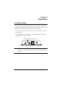
Long Reach Mode . . . . . . . . . . . . . . . . . . . . . . . . . . . . . . . . . . . . . . . . . . 15
Changing EDID formats . . . . . . . . . . . . . . . . . . . . . . . . . . . . . . . . . . . . . . 16
Appendix
Safety Instructions . . . . . . . . . . . . . . . . . . . . . . . . . . . . . . . . . . . . . . . . . . 19
General . . . . . . . . . . . . . . . . . . . . . . . . . . . . . . . . . . . . . . . . . . . . . . . 19
Rack Mounting . . . . . . . . . . . . . . . . . . . . . . . . . . . . . . . . . . . . . . . . . . 21
Technical Support . . . . . . . . . . . . . . . . . . . . . . . . . . . . . . . . . . . . . . . . . . 22

VE814A User Manual
viii
International . . . . . . . . . . . . . . . . . . . . . . . . . . . . . . . . . . . . . . . . . . . .22
North America . . . . . . . . . . . . . . . . . . . . . . . . . . . . . . . . . . . . . . . . . .22
Specifications . . . . . . . . . . . . . . . . . . . . . . . . . . . . . . . . . . . . . . . . . . . . . . 23
Ethernet Capability List . . . . . . . . . . . . . . . . . . . . . . . . . . . . . . . . . . . . . . .24
Limited Warranty. . . . . . . . . . . . . . . . . . . . . . . . . . . . . . . . . . . . . . . . . . . . 25

VE814A User Manual
ix
About this Manual
This user manual is provided to help you get the most from the VE814A unit.
It covers all aspects of installation, configuration, and operation. An overview
of the information found in the manual is provided below.
Chapter 1, Introduction introduces you to the HDMI HDBaseT Extender
with Dual Output. Its purpose, features, and installation considerations are
described and discussed.
Chapter 2, Hardware Setup introduces the panel components and describes
the steps to quickly and safely install the product.
Chapter 3, Operation explains the Long Reach Mode, its concept,
requirements, and limitations.
Appendix provides a list of safety instructions and precautions, contact
information for ATEN technical support, product specifications, and other
technical information.
Note:
Read this manual thoroughly and follow the installation and operation
procedures carefully to prevent any damage to the unit or any connected
devices.
The product may be updated, with features and functions added, improved
or removed since the release of this manual. For an up-to-date user
manual, visit http://www.aten.com/global/en

VE814A User Manual
x
Conventions
This manual uses the following conventions:
Monospaced Indicates text that you should key in.
[ ] Indicates keys you should press. For example, [Enter] means to
press the Enter key. If keys need to be chorded, they appear
together in the same bracket with a plus sign between them:
[Ctrl+Alt].
1. Numbered lists represent procedures with sequential steps.
♦Bullet lists provide information, but do not involve sequential steps.
>Indicates selecting the option (on a menu or dialog box, for
example), that comes next. For example, Start
>
Run means to
open the Start menu, and then select Run.
Indicates critical information.

1
Chapter 1
Introduction
Overview
ATEN VE814A is an HDBaseT Video Extender that is capable of sending
HDMI signals up to 100 m over a single Cat 5e/6/6a or ATEN 2L-2910 Cat 6
cable. Featuring dual synchronous outputs, the VE814A can transmit identical
outputs to two remote displays and one display at the local side. This
HDCP 2.2-compliant extender meets the HDMI Specification, including 3D,
Deep Color, the maximum data rate of 10.2 Gbps, and transmission of 4K
videos up to 100 m.
Supporting bi-directional RS-232 and full-range IR signaling pass-through, the
VE814A allows you to control an HDMI source device from the remote unit
(VE814AR) while granting access to the HDMI display device from the local
unit (VE814AT). In addition, it supports Long Reach Mode that extends HDMI
signals up to 150 m, 1080p, via a single Cat 5e/6 cable.
The VE814A is a powerful solution for where digital signage is required, such
as bars, educational spaces, and public transportation stations, allowing display
of identical contents at different spots.

Chapter 1. Introduction
2
Features
Extends HDMI signals to one local and two remote displays up to 100 m
over a single Cat 5e/6/6a or ATEN 2L-2910 Cat 6 cable
HDMI (3D, Deep Color, 4K); HDCP 2.2 compatible
Superior video quality
4K up to 100 m
1080p up to 150 m when in HDBaseT Long Reach Mode
Supports HDBaseT Long Reach Mode – extends signals up to 150 m,
1080p, via a single Cat 5e/6 cable
Extends Ethernet communication using the Ethernet pass-through port (for
device supporting the Ethernet port only)
Supports two IR channels for simultaneous IR signal transmissions,
ranged from 30 kHz to 56 kHz
EDID Expert
TM
– selects optimum EDID settings for high-quality display
and use of optimum video resolution
RS-232 channel – allows you to connect to serial terminals or serial
devices, such as touch screens and barcode scanners
Supports wide screen format
Built-in 8 kV/15 kV ESD protection
Plug-and-play
Rack-mountable

VE814A User Manual
3
Planning the Installation
Requirements
Prepare the following before installing the VE814A unit:
Considerations
Note that the maximum transmission distance varies at different parts of the
transmission depending on the transmission interface:
Note: The maximum transmission distance using a Cat 5e/6/6a or
an ATEN 2L-2910 cable can go up to 150 m when long reach mode is
enabled.
Required Equipment Details
Display device
1 HDMI display capable of the highest required
resolution.
Source device
1 source device with an HDMI port.
Cables
1 Cat 5e/6/6a cable for connecting the VE814AT and
VE814AR.
Note: For best video quality, we strongly recommend
using the ATEN 2L-2910 Cat 6 cable to connect the
VE814AT and VE814AR.
Connection Interface Distance
Computer to the VE814AT HDMI 1.8 m
VE814AT to VE814AR Cat 5e/6/6a
2L-2910
100 m*
VE814AR to the display HDMI 5 m

Chapter 1. Introduction
4
This Page Intentionally Left Blank

5
Chapter 2
Hardware Setup
Components
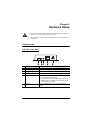
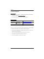
VE814AT Front View
No. Component Description
1 RS-232 serial port Connects to a computer or control system.
2 IR out Connects to an IR transmitter.
3 IR in Connects to an IR receiver.
4 Ethernet port
If there is no Ethernet port on the device, the Ether-
net capability is not supported.
For device supporting the Ethernet port, plug a Cat
5e/6/6a cable or an ATEN 2L-2910 cable which con-
nects to the local computer.
5 HDMI in Connects to the HDMI out port on a video source
device.
1. Please review the safety information regarding the placement of
this device in Safety Instructions, page 19.
2. Do not power on the VE814A until all the necessary hardware is
connected.
1 2 3 5
4

Chapter 2. Hardware Setup
6
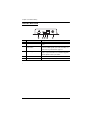
VE814AT Rear View
No. Component Description
1 HDMI out Connects to the HDMI in port on a video display
device.
2 HDBaseT long reach
mode switch
Put the switch to ON to enable the long reach mode
to transmit HDMI signals up to 150m, at 1080p. For
details, see Long Reach Mode, page 15.
3 firmware upgrade switch This function is reserved for ATEN Technical
Support. If you would like to do a firmware upgrade
yourself, please contact your dealer.
4 HDBaseT out Connects to the HDBaseT in port on a VE814AR.
5 power jack Connects to the power adapter.
1 2 4 5
3

VE814A User Manual
7
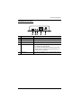
VE814AR Front View
No. Component Description
1 RS-232 serial port Connects to a computer or control system.
2 IR out Connects to an IR transmitter.
3 IR in Connects to an IR receiver.
4 Ethernet port
If there is no Ethernet port on the device, the Ether-
net capability is not supported.
For device supporting the Ethernet port, plug a Cat
5e/6/6a cable or an ATEN 2L-2910 cable which con-
nects to the local computer.
5 HDMI out 2 Connects to the HDMI in port on a video display device.
1 2 3 5
4

Chapter 2. Hardware Setup
8
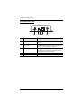
VE814AR Rear View
No. Component Description
1 HDMI out 1 Connects to the HDMI in port on a video display
device.
2 HDBaseT long reach
mode switch
Put the switch to ON to enable the long reach mode
to transmit HDMI signals up to 150m, at 1080p. For
details, see Long Reach Mode, page 15.
3 firmware upgrade switch This function is reserved for ATEN Technical
Support. If you would like to do a firmware upgrade
yourself, please contact your dealer.
4 HDBaseT in Connects to the HDBaseT out port on a VE814AT.
5 power jack Connects to the power adapter.
1 2 4 5
3

VE814A User Manual
9
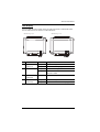
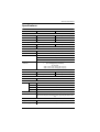
LED Display
You can find the unit’s LEDs on the top and front panel as illustrated below.
See the table below for details on LED indication.
No. LED Indication Description
1 HDMI out LED
(VE814AT)
Lights green The HDMI out signals are stable.
Blinks green The VE814AT is being upgraded for firmware.
2 power / link LED Blinks green The unit is receiving power with no data flow.
Lights green The connection between the VE814AT and
VE814AR is stable
3 HDMI 1 out LED
(VE814AR)
Lights green The HDMI out signals are stable.
4 HDMI 2 out LED
(VE814AR)
Lights green The HDMI out signals are stable.
Blinks green The VE814AR’s firmware is being upgraded.
3 4 2
1 2
WF925BU!Upq!Wjfx WF925BS!Upq!Wjfx

Page is loading ...
Page is loading ...
Page is loading ...
Page is loading ...
Page is loading ...
Page is loading ...
Page is loading ...
Page is loading ...
Page is loading ...
Page is loading ...
Page is loading ...
Page is loading ...
Page is loading ...
Page is loading ...
Page is loading ...
-
 1
1
-
 2
2
-
 3
3
-
 4
4
-
 5
5
-
 6
6
-
 7
7
-
 8
8
-
 9
9
-
 10
10
-
 11
11
-
 12
12
-
 13
13
-
 14
14
-
 15
15
-
 16
16
-
 17
17
-
 18
18
-
 19
19
-
 20
20
-
 21
21
-
 22
22
-
 23
23
-
 24
24
-
 25
25
-
 26
26
-
 27
27
-
 28
28
-
 29
29
-
 30
30
-
 31
31
-
 32
32
-
 33
33
-
 34
34
-
 35
35


ATEN VE814AT User manual
- Category
- Network switches
- Type
- User manual
- This manual is also suitable for
Ask a question and I''ll find the answer in the document
Finding information in a document is now easier with AI