Page is loading ...

Max Load Capacity For Floor Stand Only:
Two screens at 200 lb (90.7 kg) each
Max Load Capacity For Floor Stand With ACC 604:
Four screens at 200 lb (90.7 kg) each
3215 W. North Ave. • Melrose Park, IL 60160 • (800) 729-0307 or (708) 865-8870 • Fax: (708) 865-2941 • www.peerlessmounts.com
ISSUED: 02-14-06 SHEET #: 202-9099-2 06-16-06
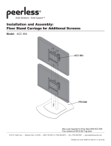
Installation and Assembly:
Floor Stand
Model: FPZ-600

2 of 7 ISSUED: 02-14-06 SHEET #: 202-9099-2 06-16-06
Note: Read entire instruction sheet before you start installation and assembly.
• Do not begin to install your Peerless product until you have read and understood the instructions and warnings
contained in this Installation Sheet. If you have any questions regarding any of the instructions or warnings, please
call Peerless customer care at 1-800-729-0307.
• This product should only be installed by someone of good mechanical aptitude, has experience with basic building
construction, and fully understands these instructions.
• Make sure that the supporting surface will safely support the combined load of the equipment and all attached hard-
ware and components.
• Never exceed the Maximum Load Capacity.
• Always use an assistant or mechanical lifting equipment to safely lift and position equipment.
• Tighten screws firmly, but do not overtighten. Overtightening can damage the items, greatly reducing their holding
power.
WARNING
Accessories
• Carriage for Additional Screens (ACC 604)
Table of Contents
Parts List .............................................................................................................................................................................. 3
Assembling Floor Stand ........................................................................................................................................................ 4
Attaching Adapter Plate to Screen with VESA 100 Mounting Pattern ................................................................................... 5
Attaching Adapter Plate to Screen with VESA 200 Mounting Pattern ................................................................................... 5
Attaching Adapter Plate to Screen with VESA 200 x 200 Mounting Pattern ......................................................................... 6
Attaching Adapter Plate to PLP Adapter Bracket ................................................................................................................. 6
Installing Flat Panel Screen on Floor Stand .......................................................................................................................... 7

3 of 7 ISSUED: 02-14-06 SHEET #: 202-9099-2 06-16-06
O
For customer care call (800) 729-0307 or (708) 865-8870.
B
D
Description Qty. Part #
Abase 1 201-1037
Bcarriage 1 201-1020
Cmain tube 2 580-1159
Dadapter plate 2 201-1022
E5/16-24 x 1/4" set screw 8 520-9566
FM6 x 20 mm serrated washer head socket pin screw 4 510-9554
GM10 x 15 mm socket head screw 4 520-9262
HM6 x 12 mm phillips screw 4 520-1128
IM6 x 20 mm phillips screw 4 520-9402
JM6 x 30 mm phillips screw 4 510-9109
KM4 x 10 mm phillips screw 4 504-9012
LM4 x 20 mm phillips screw 4 504-9020
M.198" ID x .313" OD x .437" H retaining spacer 4 590-5005
N6 mm non-security allen wrench 1 560-9716
O4 mm security allen wrench 1 560-9646
Pbumper strip 1 570-1030
Parts List
I J
K L M
A
EFH
C
G
P
N

4 of 7 ISSUED: 02-14-06 SHEET #: 202-9099-2 06-16-06
Slide two main tubes (C) onto base (A) and secure
using four set screws (E) as shown in figure 2 and
detail 1. Tighten screws using 4 mm allen wrench (O).
1
Slide carriage (B) onto main tubes (C). Slide carriage to desired height and secure using four set screws (E) as
shown in figure 3 and detail 2. Tighten screws using 4 mm allen wrench (O).
Note: Orientation of "UP" arrow is critical.
2
C
ADETAIL 1
fig 2
C
fig 3
For some situations, bumper strip (P) may be
required to keep base (A) level. If so, cut bumper
strip (P) into five equal pieces and adhere one piece
to each corner and one piece to center of bottom
side of base (A).
Note: The pieces can also be used in other locations
on the base's bottom for other situations.
P
A
3
DETAIL 2
E
E
B

5 of 7 ISSUED: 02-14-06 SHEET #: 202-9099-2 06-16-06
Choose hole pattern as shown in figure 4.2. Attach
adapter plate (D) to back of screen using four M4 x
10 mm screws (K) as shown.
Note: Orientation of "UP" arrow is critical.
*Note: If screw (K) gets less than three threads of
engagement, attach adapter plate (D) to back of
screen using four M4 x 20 mm screws (L) and four
spacers (M) as indicated below.
Skip to step 5 on page 7.
K
D
Attaching Adapter Plate to Screen with VESA 100 Mounting Pattern
4
• If screws don't get three complete turns in the screen inserts or if screws bottom out and adapter plate is still not
tightly secured, damage may occur to screen or product may fail.
WARNING
M
*For screens with a
hole pattern in a
pocket, spacers (M)
go between adapter
plate (D) and screen. M
Attaching Adapter Plate to Screen with VESA 200 Mounting Pattern
• If screws don't get three complete turns in the screen inserts or if screws bottom out and adapter plate is still not
tightly secured, damage may occur to screen or product may fail.
WARNING
Choose hole pattern as shown in figure 4.1. Attach
adapter plate (D) to back of screen using four M4 x
10 mm screws (K).
Note: Orientation of "UP" arrow is critical.
Skip to step 5 on page 7.
4
fig 4.1
D
K
fig 4.2

6 of 7 ISSUED: 02-14-06 SHEET #: 202-9099-2 06-16-06
Choose hole pattern as shown in figure 4.3. Attach
adapter plate (D) to back of screen using four M6 x
12 mm screws (H) as shown.
Note: Orientation of "UP" arrow is critical.
*Note: If screw (H) gets less than three threads of
engagement, attach adapter plate (D) to back of
screen using four M6 x 20 mm screws (I). If screw (I)
still gets less than three threads of engagement, use
four M6 x 30 mm screws (J).
Skip to step 5 on page 7.
G
4
For screen compatibility please refer to the plasma interface list on our website www.peerlessmounts.com or call
customer care for a screen specific adapter bracket (PLP models).
GENERIC ADAPTER
BRACKET
Attaching Adapter Plate to Screen with VESA 200 x 200 Mounting Pattern
• If screws don't get three complete turns in the screen inserts or if screws bottom out and bracket is still not tightly
secured, damage may occur to screen or product may fail.
WARNING
Attaching Adapter Plate to PLP Model Adapter Bracket
4
fig 4.3
D
H
fig 4.4
D
Note: Refer to PLP model adapter bracket instruction
sheet for attachment of adapter bracket to screen.
Choose hole pattern as shown in figure 4.4. Attach
adapter plate (D) to back of screen using four M10 x
15 mm screws (G) as shown. Tighten screws using
6 mm allen wrench (N).
Note: Orientation of "UP" arrow is critical.

7 of 7 ISSUED: 02-14-06 SHEET #: 202-9099-2 06-16-06
To install second screen, repeat steps four and five for back side of carriage (B).
To install additional screens, ACC 604 is required.
F
Hook adapter plate (D) onto carriage (B) and secure using two M6 x 20 mm serrated washer head socket pin screws
(F) as shown in figure 5 and detail 3. Tighten screws using 4 mm allen wrench (O).
5
DETAIL 3 fig 5
D
B
6
© 2006 Peerless Industries, Inc. All rights reserved.
Peerless is a registered trademark of Peerless Industries, Inc.
All other brand and product names are trademarks or registered trademarks of their respective owners.
/