Page is loading ...

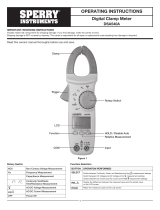
OPERATING INSTRUCTIONS
Phase Sequence and
Open Phase Indicator
Model PSI8031
IMPORTANT: RECEIVING INSTRUCTIONS Visually inspect
all components for shipping damage. If you find damage, notify the
carrier at once.
Shipping damage is NOT covered by warranty. The carrier
is responsible for all repair or replacement costs resulting from
damage in shipment.
1
I. Overview
Sperry PSI8031 Phase Sequence and Open Phase Indicator (hereinafter referred to be as PSI8031) is a handheld
battery powered instrument, widely used to identify phase orientation of three-phase industrial equipments and
motor rotation direction.
ITEM QUANTITY
The Instrument 1
Operating Manual 1
Test Leads 3
Alligator Clips 3
Carrying Bag 1
9V Battery 1
Standard Included Items:

II. Safety Information
• It is required to read through the following safety instructions prior to operation or maintenance
• Comply with local and national safety codes
• It is required to use personal protective gear
• It is required to operate the instrument as per the instructions of the manufacturer,
or otherwise the safety features/protective measures provided by the instrument may be affected
• Inspect the insulation of the test leads for damage or exposed metal; inspect testing lead for
continuity and replace the damaged testing lead
• Do not operate PSI8031 when removing any part
• Do not operate PSI8031 around explosive gas, steam or dust
• Do not operate PSI8031 in a wet place
• Do not install substitute parts or make any modification to the instrument.
• Do not try to replace the batteries if the surface of the instrument is wet.
• Always switch off the instrument before opening the battery compartment cover
for battery replacement.
• It is required to remove testing lead from the power and PSI8031 prior to replacing the battery
• Adverse impact will be caused to the measurement by the impedance generated by the transient
current of another circuit in parallel
• Please ensure the instrument operates normally prior to measuring dangerous voltage
(30V AC rms, 42 V AC peak value or 60 V DC above)
• Testing time should not exceed 10min when measuring the voltage 500V ~ 600V AC
• Firmly insert the test leads.
• Do not expose the instrument to the direct sun, high temperature and humidity or dewfall.
• Be sure to power off the instrument after use. When the instrument will not be in use for a long period,
place it in storage after removing the batteries.
• Use only a soft cloth dampened with water or neutral detergent for cleaning the meter.
Do not use abrasives, solvents or harsh chemicals. Allow to dry thoroughly before use.
• If the equipment is used in a manner not specified by the manufacturer, the protection provided
by the equipment may be impaired.
III. Functional Description
3.1 Symbols
2
Following symbols are applied on PSI8031 or in the manual.
Risk of electric shock
Warning
Dangerous voltage
Double or reinforced insulation
Grounding
AC or DC
Comply with European Union directives
CAT IV
Conforms to Overvoltage Category IV, Pollution Degree 2 as per
IEC61010-1. CAT IV refers to the degree of protection against the
transients and usually includes the equipments in fixed installations
(eg: electricity meter and primary overcurrent protection device).
WARNING: Specifies the conditions and actions that may pose hazards to the User.
CAUTION: Specifies the conditions and actions that may cause damage to PSI8031.

3.2 Instrument Description
See the instrument indicator, button and jack as shown in Figure 1:
Graphical description
3.3 Operating Instruction
3.3.1 Determine Phase Sequence (Contact Type)
a. Insert test leads (L1,L2,L3) into the corresponding input terminals of PSI8031(R, S, T) respectively and
then connect them to alligator clips.
b. Then connect alligator clips in L1, L2 and L3 order to three phases of the system
(eg: R, S and T terminals of three-phase instrument).
c. The power button of the PSI8031 is a momentary switch. The power button must be held down to perform a test.
Pressing down on the power button should cause the Power LED indicator to illuminate. Releasing the power button
should cause the Power LED indicator to turn off.
d. Press and hold the power button to begin the test. While holding the power button down observe the LEDs
that are illuminated on the PSI8031.
e. The motor rotation direction will be indicted by the illumination of the “Clockwise” (R) or “Counter-clockwise” (L)
rotation LED indicators. The motor direction indicated is as viewed from the motor shaft end.
f. The presence of each phase will be indicated by the illumination of the L1, L2, L3 phase indicators
3.3.2 Check Rotary Field (Motor Rotation, Non-Contact Type)
a. Remove all test leads from the PSI8031
b. Place the PSI8031 on the motor case in the orientation indicated by the “Motor location indicator” (See Figure 1). The
PSI8031 should be held parallel to the motor shaft with the bottom of the instrument towards the motor shaft
(As shown in figure 2)
c. With the motor running press and hold the power button to begin the test.
While holding the power button down observe the LEDs that are illuminated on
the PSI8031.
d. The motor rotation direction will be indicted by the illumination of the “Clockwise”
(R) or “Counter-clockwise” (L) rotation LED indicator. The motor direction indicated
is as seen when looking at the motor shaft. (See figure 2)
Note: This non-contact test is applicable for both single-phase and three-phase motors.
The instrument will not work with motors controlled by a frequency converter.
Figure 1
R T
S
PSI8031
CAT IV 600V
Phase input jack (R, S, T)
L1, L2, L3 phase indicators;
Clockwise rotation LED indicator;
Counter-clockwise rotation LED indicator;
Power button (momentary switch)
Motor location indicator
Power LED indicator
Instruction Table
1
2
3
4
5
6
7
8
3
Figure 2
R LED indicator is on when the motor rotates
clockwise. (As viewed from motor shaft end)

4
3.4 Detect Magnetic Field
a. Place the back of the PSI8031 against the solenoid valve and press the “ON” button.
b. Electrically activate the solenoid valve.
c. The “Clockwise” (R) or “Counter-clockwise” (L) rotation LED indicator will illuminate if a
magnetic field exists in the area.
IV. Maintenance
To prevent damage to PSI8031:
• Repair of the PSI8031 should only be performed by qualified technicians.
• Do not expose the instrument to the direct sun, high temperature and humidity or dewfall.
• When the instrument will not be in use for a long period, place it in storage after removing the batteries.
• Use only a soft cloth dampened with water or neutral detergent for cleaning the meter.
Do not use abrasives, solvents or harsh chemicals. Allow to dry thoroughly before use.
• Make sure you know clearly precise calibration procedures and function tests, and
read enough maintenance information
• Do not use corrosive or solution since those substances will cause damage to the chassis of PSI8031
• Prior to cleaning, remove all testing leads from PSI8031
Replacement and disposal of battery
• To prevent electric shocking, it is necessary to remove all testing leads from PSI8031
prior to replacing replace the battery.
• PSI8031 contains 9V/6F22 battery, do not discard the battery with other solid wastes and the used
battery should be handed over to the qualified waste collector or dangerous substance transporter for
proper treatment and disposal.
Please replace the battery as follows and see the Figure 3:
1. Remove all test leads from PSI8031.
2. Remove the rubber protective case.
3. Place the PSI8031 face down on the non-abrasive surface.
4. Remove the screw from the battery cover.
5. Remove the battery cover from the PSI8031
6. Unsnap the battery connector and remove the battery.
7. Install a new battery in the reverse order.
V. Specifications Figure 3
Ambient
Working temperature 0˚C ~ 40˚C (32°F ~ 104°F)
Storage temperature 0˚C ~ 50˚C (32°F ~ 122°F)
Altitude 2000m
Humidity <95%
Pollution Degree 2
IP grade IP 40
Mechanical
Dimensions 123mm x 71 mm x 29mm
(4.8in X 2.8in x 1.1in)
Weight 192g
Safety
Compliances Comply with IEC61010/EN61010, IEC 61557-7
Maximum operating voltage (Ume) 600V
CAT Rating CAT IV 600V
Electrical
Power 9V/6F22 battery
Battery life approximately 1 year of normal USE
Phase indication
Nominal voltage 90VAC ~ 600VAC
Frequency range (fn) 15Hz ~ 400 HZ
Nominal test current (subject to each phase) <3 mA
Non-contact rotating magnetic field Indication
Nominal voltage rotating direction value 30VAC ~ 600VAC
Frequency range (fn) 15Hz ~ 400 HZ
Nominal test current (subject to each phase) <3 mA
CAUTION
WARNING

* Note:
• The warranty is not applicable if the instrument has been: misused, abused, subjected to loads in
excess of specifications, has had unauthorized repair or has been improperly assembled or used.
• Sperry does not calibrate or repair any meters.
• Conforms to UL STD.61010-1,61010-2-030. Certified to CSA STD. C22.2 No. 61010-1,61010-2-030.
SPR_TL_060_0316_PSI8031
Lifetime Limited Warranty
Limited solely to repair or replacement; no warranty of merchantability or fitness for a particular
purpose. Product is warrantied to be free of defects in materials and workmanship for the normal life of
the product. In no event Sperry Instruments be liable for incidental or consequential damage.
Sperry Instruments
800-645-5398
Menomonee Falls, WI 53051
sperryinstruments.com
5
/