
A I R C ONDITIONI N G
Emissione/Issue//Ausgabe
Emission/ Emisión
03-22
-
Sostituisce/Supersade/Ersetzt/
Remplace/ Remplaza
Catalogo/Catalogue/Katalog/Catalogue/Catálogo
MUI01110G4601-02
UNITÀ DI RECUPERO CALORE
HEAT RECOVERY UNITS
MANUALE UTENTE
USER MANUAL
Serie/Series/Serie/Série/ Serie
OTA1 micro E

IMPORTANTE
PRIMA DI COMPIERE QUALUNQUE OPERAZIONE
RIGUARDANTE LA MACCHINA LEGGERE
ATTENTAMENTE, COMPRENDERE E SEGUIRE
TUTTE LE ISTRUZIONI DEL PRESENTE MANUALE
IMPORTANT
BEFORE PERFORMING ANY OPERATION OF THE
MACHINE CAREFULLY READ,
UNDERSTAND AND FOLLOW
ALL INSTRUCTIONS LISTED IN THIS MANUAL
INDICE
INDEX
1 - SIMBOLOGIA UTILIZZATA
2 - AVVERTENZE E REGOLE GENERALI
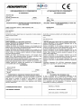
DICHIARAZIONE DI CONFORMITÀ “CE”
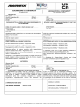
DICHIARAZIONE DI CONFORMITÀ “UKCA”
3 - IDENTIFICAZIONE UNITÀ
4 - CARATTERISTICHE TECNICHE
5 - DATI TECNICI UNITÀ
6 - DIMENSIONI E PESI MACCHINA
7 - CONTROLLI PRIMA DELLA SPEDIZIONE
8 - TRASPORTO
9 - SCARICO
(',*(%%(%*#.#&',(
(%%.&',((.#&',0#('
,(!!#(
10 - INSTALLAZIONE E MESSA IN SERVIZIO
2'#0#('#
(*&#+#-*00
' (*&0#('#)*%#&#'*#
-(!(1#'+,%%0#(')(+#0#('&',(%%&"#'
('+#*0#('#+-%%1#+,%%0#('
11 - COLLEGAMENTI ELETTRICI
"&#%,,*##
"%,,*('#(#(',*(%%((,'0
12 - MESSA IN SERVIZIO
13 - PANNELLO DI COMANDO
14 - ISTRUZIONI D’USO
15 - MODBUS
16 - ULTERIORI CONFIGURAZIONI E FUNZIONALITA’
17 - INSTALLAZIONE ACCESSORI
18 - MANUTENZIONE
19 - LOCALIZZAZIONE DEI GUASTI
20 - SMALTIMENTO
21 - PARTI DI RICAMBIO
1 - SYMBOLS USED
2 - WARNINGS AND GENERAL RULES
“EC” DECLARATION OF CONFORMITY
“UKCA” DECLARATION OF CONFORMITY
3 - IDENTIFICATION OF THE UNIT
4 - TECHNICAL FEATURES
5 - UNIT TECHNICAL DATA
6 - DIMENSION AND WEIGHTS MACHINE
7 - CHECKS BEFORE SHIPMENT
8 - TRANSPORT
9 - UNLOADING
"$+-)('*#),
(#+,#'!'"'%#'!
,(*!
10 - INSTALLATION AND START UP
2'#,#('+
,/,'*+
*%#&#'*/#' (*&,#('
'+,%%,#('%(,#(''-'#,)(+#,#('#'!
'+,%%,#('('+#*,#('+
11 - ELECTRICAL CONNECTION
#*#'!#!*&+
#'(*
12 - COMMISSIONING
13 - TOUCH SCREEN
14 - CONTROLLER USER INSTRUCTIONS
15 - MODBUS
16 - ADDITIONAL CONFIGURATIONS AND FEATURES
17 - ACCESSORIES INSTALLATION
18 - MAINTENANCE
19 - BREAKDOWN DIAGNOSTIC
20 - DISMANTLING
21 - SPARE PARTS
)!'-%##'+,%%0#('+('-,'0#('
'+,%%,#('+'#','''-%

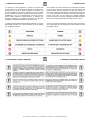
1 - SIMBOLOGIA UTILIZZATA 1 - SYMBOLS USED
La macchina è stata progettata e costruita in accordo alle
norme vigenti ed è quindi dotata di sistemi di prevenzione e
protezione per i rischi di natura meccanica ed elettrica che
possono riguardare l’operatore o l’utilizzatore. Vi sono tuttavia
dei rischi residui che possono presentarsi durante il trasporto,
l’installazione, l’uso o la manutenzione. Tali rischi possono
essere ridotti seguendo scrupolosamente le istruzioni del
manuale, utilizzando gli adeguati dispositivi di protezione
individuali e rispettando le vigenti norme di sicurezza.
The machine has been designed and constructed according
to the current norms and consequently with mechanical and
electrical safety devices designed to protect the operator or
user from possible physical damage. Residual risks during use
or in some intervention procedures on the device are however
present. Such risks can be reduced by carefully following
manual procedures, using the suggested individual protection
devices and respecting the legal and safety norms in force.
Le indicazioni più importanti riguardanti la sicurezza e il corretto
utilizzodella macchina sono accompagnate da alcuni simboli
per renderle più evidenti:
The most important information concerning safety and proper
use of themachine are accompanied by some symbols to make
them highly visible:
2 - AVVERTENZE E REGOLE GENERALI
2 - WARNINGS AND GENERAL RULES
pag.3 - Manuale di installazione, Uso e Manutenzione -
Installation, Use and Maintenance Manual

NOTE IMPORTANTI
IMPORTANT NOTES
Le unità sono progettate e costruite esclusivamente per:
- installazioni interne, salvo adottare idonei accessori che
ne consentano l’installazione all’aperto;
- per il trattamento aria degli ambienti civili, incompatibili
con gas tossici, esplosivi, in8ammabili e corrosivi (incluse
atmosfere con cloro e salsedine).
Quindi se ne fa esplicito divieto di utilizzo in quegli
ambienti dove l'aria risulti mescolata e/o alterata da altri
composti gassosi e/o particelle solide.
L'utilizzo per scopi diversi da quelli previsti, e non
conformi a quanto descritto in questo manuale, farà
decadere automaticamente qualsiasi responsabilità diretta
e/o indiretta della Ditta Costruttrice e dei suoi Distributori.
The units are designed and built exclusively for:
-internal installation, except to use speci8c option for
outdoor installation;
-for air traitment in the civil environments, incompatible
with toxic, explosive, in9ammable and corrosive
(chlorinated and saline included) gases.
Therefore it cannot be used in those environments where
the air is mixed and/or altered by other gaseous
composites and/or solid particles.
The use of the same for different purposes from those
envisioned, not conform to that described in this manual,
will make any direct and/or indirect liability of the
manufacturer automatically become null and void.
Poiché la Ditta Costruttrice è costantemente impegnata nel
continuo perfezionamento di tutta la sua produzione, le
caratteristiche estetiche e dimensionali, i dati tecnici, gli
equipaggiamenti e gli accessori, possono essere soggetti
a variazione.
Per tale motivo il produttore si riserva di apportare
qualsiasi modi8ca senza preavviso.
As our Company is constantly involved in the continuous
improvement of its production, aesthetic characteristics
and dimensions, technical data, equipment and
accessories can be subject to variation.
For this reason the manufacturer reserves the right to make
any changes without prior notice.
pag.4 - Manuale di installazione, Uso e Manutenzione -
Installation, Use and Maintenance Manual

pag.5 - Manuale di installazione, Uso e Manutenzione -
Installation, Use and Maintenance Manual

pag.6 - Manuale di installazione, Uso e Manutenzione -
Installation, Use and Maintenance Manual

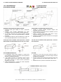
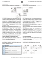
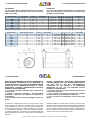
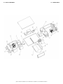
3 - IDENTIFICAZIONE UNITÀ
3 - IDENTIFICATION OF THE UNIT
Le unità sono dotate di una targhetta di identi5cazione che
riporta:
A - Marchio del Costruttore;
B - Indirizzo del Costruttore;
C - Modello unità;
D - Matricola unità;
E - Tensione; n° fasi; frequenza di alimentazione;
F - Corrente assorbita massima;
G - Codice unità;
H - Data di produzione;
I - Marcatura “CE” e "UKCA";
L - Codice a barre identi5cativo
The units feature a rating plate that describes the following:
A - Mark of the manufacturer;
B - Address of the manufacturer;
C - Unit model;
D - Unit serial number;
E - Voltage, number of phases; frequency of the power supply;
F - Max absorbed current;
G - Unit code;
H - Manufacturinga date;
I - “CE” and "UKCA" mark;
L - Bar code.
PER EVENTUALI RICHIESTE DI INFORMAZIONI
È NECESSARIO RIVOLGERSI ALLA SEDE COMUNICANDO
IL NUMERO DI SERIE DELL’UNITÀ.
WHEN CONTACTING THE OFFICE FOR ANY
INFORMATION ENQUIRIES, PLEASE PROVIDE
THE UNIT SERIAL NUMBER.
pag.7 - Manuale di installazione, Uso e Manutenzione -
Installation, Use and Maintenance Manual

4 - CARATTERISTICHE TECNICHE
4 - TECHNICAL SPECIFICATIONS
▪Recuperatore di calore entalpico statico con ef0cienza
termica 0no al 76%.
▪#97:99:7' ':945479'39+ /3 1'2/+7' ?/3)'9' )4/(+39'9'
/39+73'2+39+ +* +89+73'2+39+ '))+88/(/1/9A '997';+784
85479+1141'9+7'1+
▪/197'?/43+ *+11B'7/' /3 )1'88+ */ +,C)/+3?' # +
)43 57+C1974 "#
8:11B'7/' */ 7/334;4 C1974 "# 8:1 D:884 */ 7/57+8'
▪ 7+88489'948+-3'1'?/43+C197/8547).//39+-7'94
▪#/89+2' 24947/??'94 */ (>5'88 *+1 7+):5+7'947+ '99:'94
':942'9/)'2+39+ *'1 )43974114 +1+99743/)4 5+7 -'7'39/7+ /1
7',,7+8)'2+394 -7'9:/94 )43 1B'7/' +89+73' 6:'3*4
)43;+3/+39+
▪1+9974;+39/1'947/ )43 24947+ ' ('884 )438:24 '* '19'
57+89'?/43+ + 8/1+3?/48/9A 5488/(/1/9A */ -+89/43+ */ 1/;+11/
*/;+14)/9A
▪433+88/43/ '11+ )'3'1/??'?/43/ )43 7'))47*/ /3 2'9+7/'1+
51'89/)4
▪!:'*74 +1+997/)4 /3)47547'94 )43 8).+*' +1+99743/)' 5+7 /1
)43974114 *+11+ ,:3?/43/ */ ;+39/1'?/43+ + */ ,7++)441/3- +
5488/(/1/9A */ /39+7,'))/'2+394 97'2/9+ 57494)4114 4*(:8 5+7
1'8:5+7;/8/43+*+/5'7'2+97/*/,:3?/43'2+394
▪
Air-to-air enthalpy heat recovery device, thermal
ef0ciency up to 76%.
▪
'1;'3/?+* 89++1 8+1,8:55479/3- 5'3+18 /39+73'11> '3*
+=9+73'11>/38:1'9+*'))+88/(/1/9>,7428/*+*447
▪
# + +,C)/+3)> )1'88 C19+7
</9. 8>39.+9/) )1+'3'(1+ 2+*/' '3* "#
57+C19+7 43 ,7+8. '/7 "# C19+7 43 7+9:73 '/7
/39'0+
▪
39+-7'9+*57+88:7+8</9).,47*/79>C19+78/-3'1
▪
4947/8+* .+'9 7+)4;+7> (>5'88 *+;/)+ ':942'9/)'11>
)4397411+* (> :3/9 )439741 94 :8+ ,7+8. '/7 ,7++)441/3- <.+3
)43;+3/+39
▪
4< )438:259/43 ./-. +,C)/+3)> 14< 34/8+ */7+)9 *7/;+3
,'38</9.85++*249478
▪
:)9)433+)9/438(>)/7):1'751'89/))411'78
▪
:/19/3 +1+)97/) (4= +6:/55+* </9. 94 )439741 ,'3 '3*
(>5'88 ,:3)9/43 '3* 4*(:8 )42:3/)'9/43 57494)41 ,47 9.+
8:5+7;/8/434,9.+45+7'9/3-5'7'2+9+784,9.+:3/9
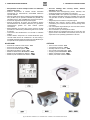
ACCESSORI
OPTIONS
▪ '33+114*/)42'3*4$4:).#)7++3 PTS
▪#+3847+*/*'5'7+9+ QSW
▪#+3847+*/:2/*/9A*'5'7+9+ USW
▪#/1+3?/'947+)/7)41'7+')'3'1+ SLC
▪4*:14*/8'3/C)'?/43+&@ BIOX
▪4*:14*/57+7/8)'1*'2+394+1+997/)4 SBE1
▪4*:14*/54897/8)'1*'2+394+1+997/)4 SBE2
▪
$4:).8)7++3)4397411+7 PTS
▪
<'1124:398+3847 QSW
▪
:2/*/9><'1124:398+3847 USW
▪
:)9)/7):1'784:3*'99+3:'947 SLC
▪
:7/,>/3-8>89+2&@ BIOX
▪
1+)97/)57+.+'9+724*:1+ SBE1
▪
1+)97/)5489.+'9+724*:1+ SBE2
5'-'3:'1+*//389'11'?/43+%84+'3:9+3?/43+
389'11'9/43%8+'3*'/39+3'3)+'3:'1

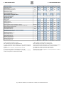
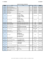
5 - DATI TECNICI UNITÀ
5 - UNIT TECHNICAL DATA
MODELLO /
MODEL
E 25H E 35H E 50H E 65H E 80H E 100H E 130H
#7:<*<**:2*67526*4.
!7526*4*2:G7?
51
#:.;;276.;<*<2,*=<24.67526*4.
!7526*4.@<.:6*4;<*<2,8:.;;=:.
#*
425.6<*B276..4.<<:2,*
4.,<:2,*487?.:;=884A
(81B
7::.6<.*;;7:+2<*5*;;25*<7<*4.
&7<*4/=4447*-*58.:*0.
LIMITI OPERATIVI /
WORKING LIMITS
76-2B2762-2.;.:,2B274252<.
252<?7:3260<.58.:*<=:.
C ECE
VENTILATORI /
FANS
&2874702*57<7:.
7<7:<A87470A
!C>.47,2<D
!=5+.:7/;8..-;
76<:7447>.6<24*B276.
*6,76<:74
*6
(%
*6
(%
*6
(%
*6
(%
*6
(%
*6
(%
*6
(%
#7<.6B*;8.,2F,*26<.:6*-2>.6<24*B276.%#26<
6<.:6*4;8.,2F,/*687?.:7/>.6<24*<276,75876.6<;%#26<
)5;
#7<.6B**;;7:+2<*67526*4.<7<*4.
&7<*467526*487?.:268=<
3)
2>.447-28:.;;276.;767:*
%7=6-8:.;;=:.4.>.4
-
RECUPERATORE DI CALORE /
HEAT EXCHANGER
/F,2.6B*<.:52,*26>.:6*4.
)26<.:<1.:5*4./F,
/F,2.6B*.6<*482,*26>.:6*4.
)26<.:.6<1*48A./F,
/F,2.6B*<.:52,*.;<2>*
%=55.:<1.:5*4./F,
/F,2.6B*.6<*482,*.;<2>*
%=55.:.6<1*48A./F,
/F,2.6B*<.:52,**;.,,7
:A<1.:5*4./F,2.6,A
*6 *6=*4.-*;.4.<<7:.7<*;<2.:*
(% 7-=4*B276.-*;.6;7:.9=*42<D=52-2<D*:2*
2>.447 -2 8:.;;276. ;767:* >*4=<*<* * 5 -* 5*6-*<*.;8=4;276.
,*6*42BB*<*:28:.;* *:2* .;<.:6* ,*6*42BB*<*4*<7 2;8.B2762 *44. ,76-2B2762
67526*42
:2*.;<.:6*C'$*:2**5+2.6<.C'$
:2*.;<.:6*C'$*:2**5+2.6<.C'$
%.,76-7 :.074*5.6<7 ' *44* 8:.;;276. 67526*4.
,76-2B2762-2<.58.:*<=:*.=52-2<D:2/.:2<.*!
*6 *6=*4+A;.4.,<7:;?2<,17:,76<:748*6.4
(% 7-=4*<276+A*2:9=*42<A7:*2:1=52-2<A;.6;7:
%7=6- 8:.;;=:. 4.>.4 ,*4,=4*<.- *< 5 /*: /:75 -=,<.- ;=884A.@1*=;<
*2:-=,<.-:.<=:6/:.;1*2:26<*3.;.:>2,.;2-.*<67526*4,76-2<276;
"=<;2-.*2:*<C$:775*2:*<C$
"=<;2-.*2:*<C$:775*2:*<C$
$./..: <7 ' :.0=4*<276 *< 67526*4 8:.;;=:. *2: ,76-2<276;
:./.:<7!;<*6-*:-
8*0 *6=*4.-226;<*44*B276.';7. *6=<.6B276.
6;<*44*<276';.*6- *26<.6*6,. *6=*4

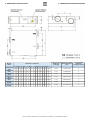
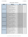
6 - DIMENSIONI E PESI MACCHINA
6 - DIMENSION AND WEIGHTS MACHINE
Modello
Model
Dimensione /
Dimension
Peso netto / lordo
Weight net /
gross [Kg]
Dimensioni imballo
Packing dimensions
[mm]
Sovrapponibilità
imballaggi
Packaging overlap
A B C D E F G L T K M N P R S Y
OTA1 micro
E25H 599 814 100 150 675 657 19 650 315 111 270 315 111 111 142 142 30 / 33 1070x755x350 6
OTA1 micro
E35H 804 814 100 150 675 862 19 855 480 111 270 480 111 111 162 162 37 / 41 1070x960x350 6
OTA1 micro
E50H 904 894 107 200 754 960 19 955 500 135 270 500 135 135 202 202 43 / 47 1125x1060x350 6
OTA1 micro
E65H 884 1186 85 250 1115 940 19 945 428 170 388 428 170 170 228 228 65 / 70 1390x1055x455 5
OTA1 micro
E80H 1134 1186 85 250 1115 1190 19 1200 678 170 388 678 170 170 228 228 71 / 76 1390x1305x455 5
OTA1 micro
E100H 1216 1199 85 250 1130 1273 19 1290 621 171 388 621 146 241 151 442 83 / 88 1475x1420x450 5
OTA1 micro
E130H 1216 1199 85 250 1130 1273 19 1290 621 171 388 621 146 241 151 442 83 / 88 1475x1420x450 5
pag.10 - Manuale di installazione, Uso e Manutenzione -
Installation, Use and Maintenance Manual

7 - CONTROLLI PRIMA DELLA SPEDIZIONE
7 - CHECKS BEFORE SHIPMENT
Tutte le unità, prima di essere spedite, sono sottoposte ad una
serie di controlli di seguito elencati.
All the units, before being sent, undergo a series of checks, as
listed below.
▪Ispezione visiva sulle 3niture.
▪Veri3ca integrità di tutti i componenti.
▪Veri3che di sicurezza elettrica.
▪Prova di funzionamento dei ventilatori.
▪Applicazione delle targhette di identi3cazione.
▪
Visual inspection of the 3nishes.
▪
Checks to ensure all the components are integral.
▪
Electrical safety checks.
▪
Functional test on the electric fans.
▪
Application of the identi3cation plates.
8 - TRASPORTO
8 - TRANSPORT
▪Le unità trattamento aria e i loro accessori sono inseriti in
scatole di cartone che dovranno rimanere integre 3no al
momento del montaggio.
▪I componenti che, per esigenze tecniche, costruttive, di
trasporto o qualsivoglia, non vengono montati a bordo
macchina, ma spediti separatamente all’interno dell’unità
o meno, vengono protetti con adeguati involucri e
debitamente menzionati sulla bolla di accompagnamento
delle merci.
▪Si dif3da dal sovrapporre qualsiasi altro materiale sulla
merce: la Ditta Costruttrice declina ogni responsabilità in
caso di danni derivanti da tale carico.
▪
The air handling units are packed in cardboard boxes that
must remain intact until assembly.
▪
The components that, due to technical, constructional,
transport or other requirements are not 3tted on the unit,
but sent separately either inside the unit or otherwise, are
specially protected and duly described on the packing list.
▪
No other material must be stacked on the products: the
Manufacturer declines all liability in the event of damage
deriving from such loads.
IL FISSAGGIO DEL CARICO SUL CAMION È A CARICO
DEL TRASPORTATORE E DEVE ESSERE ESEGUITO, CON
CORDE O CINGHIE, IN MANIERA DA NON DANNEGGIARE
L’INVOLUCRO.
THE FASTENING OF THE LOAD ON THE TRUCK IS THE
RESPONSIBILITY OF THE CARRIER, AND MUST BE
PERFORMED, USING STRAPS OR ROPES, SO AS TO
AVOID DAMAGING THE PACKAGING
9 - SCARICO
9 - UNLOADING
9.1 CONTROLLO AL RICEVIMENTO
9.1 CHECKS UPON RECEIPT
Si consiglia che al ricevimento della merce, prima dello
scarico, sia effettuato un controllo su tutto il materiale in
consegna al 3ne di veri3care l’esistenza di eventuali danni
causati dal trasporto. Gli eventuali danni devono essere
debitamente comunicati al vettore e speci3cati nella clausola di
riserva riportata nella bolla di accompagnamento.
When receiving the goods, before unloading, all the material
delivered must be checked to ascertain the presence of any
damage caused during transport. Any damage found must be
reported to the carrier, accepting the goods with reservation and
specifying the type of damage on the delivery documents.
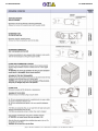
9.2 SOLLEVAMENTO E MOVIMENTAZIONE
9.2 HOISTING AND HANDLING
E’ vivamente consigliato:
It is strongly recommended:
PER LA MOVIMENTAZIONE UTILIZZARE, IN FUNZIONE
DEL PESO, MEZZI ADEGUATI COME PREVISTO DALLA
DIRETTIVA 89/391/CEE SUCCESSIVE
MODIFICHE
WHEN HANDLING THE UNITS, USE SUITABLE MEANS
ACCORDINGTHE WEIGHTS INVOLVED, AS ENVISAGED
BY EC DIRECTIVE 89/391 AND SUBSEQUENT
AMENDMENTS
▪Il peso di ogni singola macchina è riportato sul presente
manuale.
▪Evitare rotazioni senza controllo.
▪Appoggiare con prudenza la merce in modo da evitarne
bruschi spostamenti o, peggio, cadute.
▪
The weight of the units is shown on this manual.
▪
Avoid uncontrolled rotations.
▪
Place the goods down with care, avoiding sudden
movements or, worse, dropping the goods.
9.3 STOCCAGGIO
9.3 STORAGE
In caso di stoccaggio prolungato prima dell’installazione, le
macchine dovranno essere protette dalla polvere, dalle
intemperie e tenute lontane da fonti di calore e vibrazioni.
In the event of extended storage before installation, keep the
units protected from dust and bad weather and away from
sources of vibrations and heat.
LA DITTA COSTRUTTRICE DECLINA OGNI
RESPONSABILITÀ PER DANNEGGIAMENTI DELLA
MERCE DOVUTI AD UNO SCARICO NON CORRETTO O A
NON ADEGUATA PROTEZIONE DALLE INTEMPERIE
THE MANUFACTURER DECLINES ALL LIABILITY FOR
DAMAGE DERIVING FROM INCORRECT UNLOADING OR
INADEQUATE PROTECTION OF THE UNITS AGAINST THE
ELEMENTS.
pag.11 - Manuale di installazione, Uso e Manutenzione -
Installation, Use and Maintenance Manual

10 - INSTALLAZIONE E MESSA IN SERVIZIO
10 - INSTALLATION AND START UP
10.1 DEFINIZIONI
10.1 DEFINITIONS
UTENTE - L'utente è la persona, l'ente o la società, che ha
acquistato o af3ttato la macchina e che intende usarla per gli
scopi concepiti.
UTILIZZATORE / OPERATORE- L'utilizzatore o operatore, è la
persona 3sica che è stata autorizzata dall'utente a operare con
la macchina.
PERSONALE SPECIALIZZATO- Come tali, si intendono quelle
persone 3siche che hanno conseguito uno studio speci3co e
che sono quindi in grado di riconoscere i pericoli derivati
dall'utilizzo di questa macchina e possono essere in grado di
evitarli.
CUSTOMER - The customer is the person, the agency or the
company who bought or rented the unit.
USER / OPERATOR- The operator or user is the physical
person who uses the unit for the purpose for which it was
designed.
SPECIALISTIC STAFF- It is composed by the physical trained
persons, able to recognize any danger due to the proper and
improper use of the unit and able to avoid or repair it
in4ammable or toxic gases at a high temperature.
10.2 NORME DI SICUREZZA
10.2 SAFETY STANDARDS
LA DITTA COSTRUTTRICE DECLINA QUALSIASI
RESPONSABILITÀ PER LA MANCATA OSSERVANZA
DELLE NORME DI SICUREZZA E DI PREVENZIONE DI
SEGUITO DESCRITTE. DECLINA INOLTRE OGNI
RESPONSABILITÀ PER DANNI CAUSATI DA UN USO
IMPROPRIO DELL’UNITÀ E/O DA MODIFICHE ESEGUITE
SENZA AUTORIZZAZIONE.
THE MANUFACTURER DECLINES ALL RESPONSIBILITY
FOR THE FAILURE TO COMPLY WITH THE SAFETY AND
ACCIDENT-PREVENTION STANDARDS DESCRIBED
BELOW. IT ALSO DECLINES ALL LIABILITY FOR DAMAGE
CAUSED BY IMPROPER USE OF THE UNIT AND/OR
MODIFICATIONS PERFORMED WITHOUT
AUTHORISATION.
L'INSTALLAZIONE DEVE ESSERE EFFETTUATA DA
PERSONALE SPECIALIZZATO.
SPECIALISED STAFF MUST
PERFORM INSTALLATION.
▪Nelle operazioni di installazione, usare un abbigliamento
idoneo e antinfortunistico, ad esempio: occhiali, guanti, ecc.
come indicato dalle normative vigenti.
▪Durante l'installazione operare in assoluta sicurezza,
ambiente pulito e libero da impedimenti.
▪Rispettare le leggi in vigore nel Paese in cui viene installata
la macchina, relativamente all'uso e allo smaltimento
dell'imballo e dei prodotti impiegati per la pulizia e la
manutenzione della macchina, nonché osservare quanto
raccomanda il produttore di tali prodotti.
▪Prima di mettere in funzione l'unità controllare la perfetta
integrità dei vari componenti e dell'intero impianto.
▪Evitare assolutamente di toccare le parti in movimento o di
interporsi tra le stesse.
▪Non procedere con i lavori di manutenzione e di pulizia, se
prima non è stata disinserita la linea elettrica.
▪La manutenzione e la sostituzione delle parti danneggiate
o usurate deve essere effettuata solamente da personale
specializzato eseguendo le indicazioni riportate in questo
manuale.
▪Le parti di ricambio devono corrispondere alle esigenze
de3nite dal Costruttore.
▪In caso di smantellamento dell’unità, attenersi alle
normative antinquinamento previste.
▪
Wear suitable and accident-prevention clothing during
installation, for example: goggles, gloves etc. as indicated in
the current regulation.
▪
During installation operate in complete safety, clean
environment and free from obstructions.
▪
Respect the laws in force, in the Country in which the
machine is installed, relative to use and disposal of
packaging and the products used for cleaning and
maintenance of the machine, as well as complying with that
recommended by the producer of these products.
▪
Before starting the unit, check the perfect integrity of the
various components of the entire plant.
▪
Do not touch moving parts or intervene between these.
▪
Do not perform maintenance and cleaning until the electric
line has been connected.
▪
The maintenance and replacement of damaged or worn
parts must only be performed by specialised staff and
following the indications given in this manual.
▪
The spare parts must correspond to the requirements
de3ned by the manufacturer.
▪
If the unit must be dismantled, follow the envisioned anti-
pollution standards.
N.B. L'installatore e l'utilizzatore nell'uso dell’unità devono
tenere conto e porre rimedio a tutti gli altri tipi di rischio
connessi con l'impianto. Ad esempio rischi derivanti da
ingresso di corpi estranei, oppure rischi dovuti al
convogliamento di gas pericolosi in;ammabili o tossici ad
alta temperatura.
N.B. When using the unit, the installer and user must
consider and solve all risks connected to theplant. For
example, risks deriving from the entry of foreign bodies or
risks due to the conveying of dangerous in<ammable or
toxic gases at a high temperature.
pag.12 - Manuale di installazione, Uso e Manutenzione -
Installation, Use and Maintenance Manual

!% #%
!! !!"
%
$!
▪4)6%6) 6-74)88%2(3 0) 2361) (- 7-'96)>>% -2 :-+36)
%'')68%2(37- ()00% 79*C'-)28) 0-&)68? (- 13:-1)283 ) ()00%
490->-%()+0-%1&-)28-(--278%00%>-32)
▪"7%6) -(32)3 %&&-+0-%1)283 %28-2*36892-78-'3 ) (-7437-8-:-
-2(-:-(9%0-(-4638)>-32)3'',-%0-+9%28-)''
▪!6%74368%6) 0% 7)>-32) -1&%00%8% -0 4-A 4377-&-0) :-'-23 %0
093+3(--278%00%>-32)
▪3273:6%44366)%886)>>-34)7-790092-8?-1&%00%8%
▪3297%6)092-8?'31)()437-834)6%886)>>-(-'%28-)6)
▪:-8%6) (- 83''%6) 0) 4%68- 13&-0- ) (- 97%6) 0) 78)77) '31)
4928-(-7300):%1)28313:-1)28%>-32)
▪#)6-C'%6)0%4)6*)88%-28)+6-8?()-:%6-'31432)28-()0092-8?
▪
$36/ ;,-0) 1))8-2+ 8,) '966)28 7%*)8= 6)+90%8-327 )2796-2+
79*C'-)2874%')8313:)%2(8,)'0)%20-2)773*.3&7-8)
▪
$)%6 4638)'8-:) '038,-2+ %2( 4)6732%0 4638)'8-:) )59-41)28
+0%77)7+03:)7)8'
▪
3:) 8,) 4%'/)( 7)'8-32 %7 '037) %7 4377-&0) 83 8,) 40%')
3*-278%00%8-32
▪
328 40%') 83307 36 38,)6 .3&7-8) )59-41)28 3:)6 8,) 4%'/)(
92-8
▪
32897)8,)92-8%7%7836)3*=%6(83307
▪
328839',13:-2+4%687%2((32897)8,)1%779443687
▪
,)'/8,)*900-28)+6-8=3*%0092-8'31432)287
" !%
%!
!! !
"! !
▪#)6-C'%6) ',) -0 4-%23 (- %443++-3 3 (- 7378)+23 7-% -2 +6%(3
(- 7344368%6) -0 4)73 ()00%) 1%'',-2%) ) 8%0) (% 232
'%97%6):-&6%>-32-
▪#)6-C'%6) ',) -0 4-%23 (- %443++-3 3 (- 7378)+23 7-%
4)6*)88%1)28) 36->>328%0) 32() 4)61)88)6) -0 '366)883
%''344-%1)283()00):%6-)7)>-32-
▪32 437->-32%6) 0B92-8? -2 03'%0- -2 '9- 7-%23 46)7)28- +%7
-2C%11%&-0- 7378%2>) %'-() %++6)77-:) ) '36637-:) ',)
4377323 (%22)++-%6) - :%6- '31432)28- -2 1%2-)6%
-66)4%6%&-0)
▪6):)()6) 74%>- 8)'2-'- %()+9%8- 8%0- (% +%6%28-6) 0)
34)6%>-32- (- -278%00%>-32) 232',@ (- 1%298)2>-32) ) (-
7378-89>-32)()-'31432)28-59%0-&%88)6-)C086-)''
▪)00B):)289%0-8? ',) 0% 1%'',-2% ()&&% )77)6) -278%00%8%
7374)7% &-73+2% 46):)()6) 92 7-78)1% (- %++%2'-3 %
73*C883 4)6 '-%7'92% ()00) 7)>-32- ',) '31432+323 0B92-8? (-
86%88%1)283
▪
%/) 796) 8,%8 8,) 7944368 796*%') -7 %&0) 83 7944368 8,)
;)-+,83*8,)92-892-87%2(;-00238'%97):-&6%8-327
▪
%/) 796) 8,%8 8,) 7944368 796*%') -7 4)6*)'80= ,36->328%0 73
%783%003;8,)'366)'8'3940-2+3*8,):%6-3977)'8-327
▪
):)6 437-8-32 8,) 92-8 -2 63317 ;,)6) 8,)6) %6) D%11%&0)
+%7)7 36 %'-(-' %++6)77-:) 36 '36637-:) 79&78%2')7 8,%8
1%=-66)4%6%&0=(%1%+)8,):%6-397'31432)287
▪
)%:) % 1-2-191 %13928 3* *6)) 74%') %6392( 8,) 92-8
%7 7,3;2 -2 8,) C+96) 73 %7 83 %003; *36 -278%00%8-32
1%-28)2%2') %2( 8,) 6)40%')1)28 3* '31432)287 79', %7
'3-07C08)67)8'
▪
*8,)92-8-7,92+*6318,)')-0-2+%008,)7)'8-327
! !! %!"7
! !6!
# " %
"!%
!! $!!
!$!"!! !
$
!
6-%74907%
6-%78)62%
6-%(--46)7%
6-%(-%2(%8%
<,%978-6
98(336-66)7,-6
)8962-6
9440=-6
1()..1
1().
.4)55&/-0-/&'1042131*8441
00)2').-0+,)-+,4
4%+%29%0)(--278%00%>-32)"73)%298)2>-32)
278%00%8-32"7)%2(%-28)2%2')%29%0

10 - INSTALLAZIONE E MESSA IN SERVIZIO
10 - INSTALLATION AND START UP
10.5 CONSIDERAZIONI
SULL’INSTALLAZIONE
10.5 INSTALLATION
CONSIDERATIONS
SUPPORTI STRUTTURALI ED INSTALLAZIONE
STRUCTURAL SUPPORTS AND INSTALLATION
)')) &% % 4#+++ &% ,)% 1 &%
)&# #
%*+##) &$ $&*+)+& ## $$ % (, *&')
%*+##1 &%-**)# -##+4**+*#$%+
$%+ &**)-%1 # &))++& 4** & '&+)
,*) #* &% %% ## '') +,) - )1 &%
** -
-%+,#$%+ ,+ # 11) ,%+ %+ - )%+ *, %# %#
*& ')1 ### %$%+&&%#&##3,% +2
%*+##) +& ')') *, +# +) %)* . +
!,*+#%,+*%*"+*
%*+## * *&.% 0 + $ &- %*+##+ &% $,*+
#-#%*,)#0*+%
#,) +& &*)- ')&') 4/ % &,# )*,#+ % %!,)0
(, '$%+$%/** -- )+ &%
&** #0 ,* %+ - )+ &% !& %+* + ,+* ) %&+ # %
. ++,% +-%+*
L’unità può essere installata anche capovolta a seconda
delle esigenze di ispezionabilità e di raccordo con i canali.
The unit can be installed turned upside down, if need for
easy inspection.
COLLEGAMENTI AERAULICI
DUCTING
# &##$%+& ## & ##,% +2 &%&++ -
**) * ##+& ') - +) ') + ) - ) *'++) #
)++ - )&#$%+ ')+ %%+
, %# ) %%&-& *',#* &% -&%& **)
#)$%+ %# %+ -)*& # **& %##& *&& *+)%&
') - +) # %)**& (, ' &-% %# %1 &%
*,) +
*&#) ,+$%+ &%&++ ') - +) *')* &%
+)$ &)$1 &% &%%*
&%%+ &% & ,% + -%+* % ,+* *&,# +' &)
*# +& ')-%+ ) #" % *&,# &$'#0 +& )#-%+
, # %*%),#+ &%*
+.& &,+&&) -%+* *&,# &.%.) +&.) +
&,+* +& ')-%+ %0 ) % .+) %)** %#
%*,#++,+*+&')-%+&%%*+ &%%+#&**
'%,# %*+##1 &%*&%,+%1 &%
%*+##+ &%*% %+%%%,#

10 - INSTALLAZIONE E MESSA IN SERVIZIO
10 - INSTALLATION AND START UP
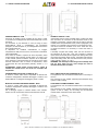
1. Assicurarsi che l'altezza del sof:tto non sia inferiore alle
:gure nella colonna B della tabella.
2. L'apparecchio non deve essere installato vicino ai fumi della
caldaia.
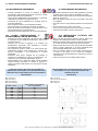
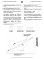
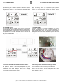
3. Il fenomeno seguente dovrebbe essere evitato
nell'installazione di canalizzazioni.
4. Evitare l’uso di canali ;essibile per lunghi tratti rettilinei.
5. Le serrande tagliafuoco devono essere montate secondo le
norme antincendio nazionali e locali.
6. L'apparecchio non deve essere esposto a temperature
ambiente superiori a 40°C e non deve essere esposto a
super:ci roventi o :amme libere.
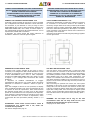
7. Adottare tutti gli accorgimenti necessari per evitare punti di
rugiada o gelo.
Come indicato dal diagramma qui sotto, nell'unità potrà
prodursi condensa o ghiaccio se la retta AC, che unisce
il punto delle condizioni di temperatura e umidità dell'aria
esterna C a quello ambiente A, passa all’esterno della curva
di saturazione. Se si veri:casse questa situazione utilizzare
un pre-riscaldatore dell’aria di rinnovo per passare da B a B’
e portare C a C’, evitando così la formazione di condensa e
ghiaccio.
N.B. il funzionamento del pre-riscaldatore deve essere
interbloccato con i ventilatori, pena il rischio di
incendio!
8. Per evitare ricircolo tra l’aria espulsa e l’aria di rinnovo, la
distanza tra le due aperture installate sulla parete esterna
deve essere superiore a 1000 mm.
1.
Be sure the ceiling height is no less than the Figures in
above table B column.
2. Unit must not be installed close to boiler ;ues.
3. Following phenomenon should be avoided in the ducting
installation.
4. Exessive use of ;ex-duct and long ;ex-duct runs should be
avoided.
5. Fire dampers must be :tted as per national and local :re
regulations.
6. Unit must not be exposed to ambient temperature above
40°C and should not face an open :re.
7.
Take action to avoid dew and frost.
As shown by drawing below, unit will produce dew or frost
when saturation curve is formed from A to C. Use pre-heater
to ensure conditions are kept to right of the curve (B to B’ ,
to move C to C’) to prevent condensation or frost formation.
If heater is equipped to the unit, operation of heater
should be synchronous with the unit, so that the heater
starts to work only when unit starts. Warning: risk of
2re!
8.
To avoid the outdoor exhaust air cycling back to indoor, the
distance between the two vents installed on the outside wall
should be over 1000 mm.
pag.15 - Manuale di installazione, Uso e Manutenzione -
Installation, Use and Maintenance Manual

11 - COLLEGAMENTI ELETTRICI
11- ELECTRICAL CONNECTION
PERICOLO!
L'alimentazione deve essere isolata durante l'installazione
e prima della manutenzione per evitare lesioni da scosse
elettriche. Le speci@che dei cavi devono corrispondere
rigorosamente ai requisiti tecnici, altrimenti possono
causare guasti e pericolo di folgorazione o incendio.
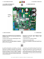
L'alimentazione è AC 230V / 50 - 60 Hz monofase e messa
a terra. Aprire il coperchio della scatola elettrica, collegare
i 3 @li (L/N/PE) ai morsetti e collegare il cavo del pannello
di controllo alla scheda secondo lo schema di cablaggio, e
unire il pannello di controllo al cavo.
Si consiglia di installare un dispositivo di @ssaggio del
cavo di alimentazione sulla parete/ventilatore.
DANGER!
Power must be isolated during installation and before
maintenance to avoid injury by electric shock. The
speci@cations of cables must strictly match the
requirements, otherwise it may cause performance failure
and danger of electric shock or @re.
Power supply is AC 230V / 50 - 60 HZ 1 Phase and ground.
Open the cover of electrical box, connect the 3 wires (L/N/
PE) to the terminals and connect the cable of the control
panel to the board according to the wiring diagram, and
join the control panel to the cable.
A cable @xing device is recommended to @x the power
cable on the wall/ventilator by installer.
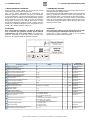
Modello
Model
Speci@ca cavo di alimentazione
Spec. of power supply cable
Speci@ca cavo segnali
Spec. of normal controller cable
OTA1 micro E25H 2 x 1.5 mm² 2 x 0.5 mm²
OTA1 micro E35H 2 x 1.5 mm² 2 x 0.5 mm²
OTA1 micro E50H 2 x 1.5 mm² 2 x 0.5 mm²
OTA1 micro E65H 2 x 1.5 mm² 2 x 0.5 mm²
OTA1 micro E80H 2 x 1.5 mm² 2 x 0.5 mm²
OTA1 micro E100H 2 x 1.5 mm² 2 x 0.5 mm²
OTA1 micro E130H 2 x 1.5 mm² 2 x 0.5 mm²
ATTENZIONE!
Il fabbricante non accetta alcuna responsabilità per
eventuali problemi causati dalla reingegnerizzazione
autonoma e non autorizzata dell'utente ai sistemi elettrici e
di controllo.
WARNING!
We do not accept any liability for any problems caused
by the user's self and non-authorized reengineering to the
electrical and control systems.
pag.16 - Manuale di installazione, Uso e Manutenzione -
Installation, Use and Maintenance Manual

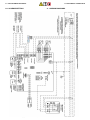
11 - COLLEGAMENTI ELETTRICI
11- ELECTRICAL CONNECTION
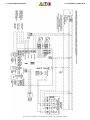
11.1 SCHEMI ELETTRICI
11.1 WIRING DIAGRAMS
pag.17 - Manuale di installazione, Uso e Manutenzione -
Installation, Use and Maintenance Manual

11 - COLLEGAMENTI ELETTRICI
11- ELECTRICAL CONNECTION
pag.18 - Manuale di installazione, Uso e Manutenzione -
Installation, Use and Maintenance Manual

11 - COLLEGAMENTI ELETTRICI
11- ELECTRICAL CONNECTION
11.2 SCHEDA ELETTRONICA DI
CONTROLLO E POTENZA
11.2 MAIN BOARD PCB
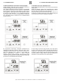
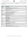
12 - MESSA IN SERVIZIO
12 - COMMISSIONING
Veri3care che le dimensioni del cavo, gli interruttori e i
collegamenti a 3lo siano corretti prima delle seguenti fasi
di messa in servizio.
Check that all cable sizes, circuit breakers and wire
connections are correct before following below
commissioning steps.
1) Premere il tasto On/Off per accendere/spegnere l’unità.
1) Press button to turn On/Off the ventilator.
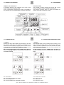
2) Veri3care la taglia dell’unità.
Il parametro che identi=ca la taglia dell’unità è impostato in
fabbrica. Tuttavia se è necessario veri=carlo e/o modi=carlo,
premere per 6 secondi (MODE)
2) Match the correct speed to ERV.
The parameter that identi=es the size of the unit is factory set.
However, if it is necessary to verify and/or modify it, press
(MODE)
per passare all’impostazione dei parametri: il numero del
parametro viene visualizzato al centro dello schermo. Premere
il tasto SET ed impostare il parametro n°21 (vedere lista
parametri più avanti); premere brevemente MODE per inserire
il valore del parametro. Il valore di default “0” lampeggia
nell’angolo in alto a destra sullo schermo, premere i pulsanti Su
e Giù per caricare il valore in base alla tabella sottostante (ERV
codice Vs Modelli), quindi premere nuovamente il tasto SET per
confermare l'impostazione.
for 6 seconds to enter parameters setting and at this time the
parameter number is shown in the middle of screen, press
button SET to parameter No.21 (refer to parameters list in
comming page) then press MODE shortly to enter the
parameter setting, default value “0” blink at the top right corner,
press Up and Down buttons to charge the value according to
below table (ERV code Vs Models) then press button SET again
to con=rm setting.
pag.19 - Manuale di installazione, Uso e Manutenzione -
Installation, Use and Maintenance Manual

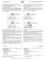
-# *(18 *$112/$ 0-,#$ 1$+.$/ 12/$ $ 3$*-"(18 #$*
3$,1(* 1-/$
7*2*7* '7*;*2*39* .1 9&894 5*7 5&88&7* &11& 24)&1.9A
&7.& *89*73& &7.& ). 7.57*8& &7.& ). 2&3)&9& 4
&7.& ). *85:18.43* (4397411&7* (-* 1& 9*25*7&9:7& 8.&
(477.8543)*39*
9 .-00(!(*$ /$&-* /$ (,#(.$,#$,1$+$,1$ ( #2$ 3$,1(* 1-/(
,$** +-# *(18 +-#(:" /$ * 3$*-"(18 #$* 3$,1(* 1-/$ #(
+ ,# 1 ./$+$,#- ( 1 01( ▲$▼ ,$** +-# *(18 /(.$1$/$
* 01$00 ./-"$#2/ .$/ /$&-* /$ (* 3$,1(* 1-/$ #(
$0.2*0(-,$
'$")1'$+-#$ ,#% ,0.$$#04(1"'
7*88 ':9943 8-4791> 94 8<.9(- 94 :98.)* &.7
*9:73 &.7 :551> &.7 47 =-&:89 &.7 24)*
(-*(0 <-*9-*7 9-* 9*25*7&9:7* 4+ 9-* (477*8543).3, 24)* .8
(477*(9
, (,#$.$,#$,1 % , 0.$$# + , &$+$,1 !$14$$, 02..*6
,# $5' 201 (0 .-00(!*$ 2,#$/ +-#$ ./$00
▲
,#
▼
1- "' ,&$ 1'$ 02..*6 % , 0.$$# 2,#$/ +-#$ ./$00
▲
,#
▼
1-"' ,&$1'$$5' 201% ,0.$$#
-#$**--#$* -#("$-#$
OTA1
OTA1
OTA1
OTA1
OTA1
OTA1
OTA1
2,7(-,$!6. 00.$/%/$$"--*(,&
E&?.43&2*394 )*1 '>5&88 &;;.*3* 97& @ * @ ).
9*25*7&9:7& *;*39:&12*39* 57*2*7* 5*7
;.8:&1.??&71& * .1 ;&147* 7.1*;&94 8. 974;& .3 6:*894 .39*7;&114
.1 '>5&88 8. &57.7A &:942&9.(&2*39* * 8. ;:41* 24).H(&7*
1& 9*25*7&9:7& ). 8*9 54.39 '>5&88 5*7 *8*25.4 & @
57*2*7* .1 5:18&39* 5.D ). 8*(43). 5*7 &((*)*7* &1
5&7&2*974.25489&?.43*
7*2*7* .1 9&894 ! 5*7 5&88&7* &1 5&7&2*974 3:2*74
;&147* ). )*+&:19 5&7. & @ B ;.8:&1.??&94 3*11&3,414 .3 &194
& )*897& 8:1 ).851&> 6:.3). 57*2*7* '7*;*2*39* .1 9&894
5*7 *397&7* 3*11E.25489&?.43* 57*2*3)4 . 9&89. ▲*▼
.25489&3)4 .1 ;&147* 8: $ $ )*;* *88*7* .3+*7.47* & @
9*25*7&9:7& &99:&1* 6:.3). 57*2*7* ! 5*7 (43+*72&7*
43 14 89*884 24)4 5*7 .25489&7* .1 ;&147* )*1 5&7&2*974
3:2*74 (42* % 8* $ 9*25*7&9:7& $ %
4. .1 '>5&88 8. &57.7A &:942&9.(&2*39* &5*794 1:9*39* 5:C
7*,41&7* . ;&147. 84994 . 5&7&2*97. * 5*7 7*3)*7* $ 4
$%6:.3)..1'>5&888.(-.:)*7A&:942&9.(&2*39*
( ./$& #( % /$ 11$,7(-,$ "'$ (* . 00 &&(- # !6. 00
.$/1-"'(20-0 /8#("(/" +(,21-(,/(1 /#-
'$")1'$-.$/ 1(-,-%%/$$"--*(,&!6. 00
!-* )*+&:19 45*3.3, 9*25*7&9:7* 4+ '>5&88 .8 '*9<**3 @
&3) @ &)/:89&'1* 57*88 ':9943 94 (-*(0 9-*
9*25*7&9:7* 4+ + 9-* 57*8*39 9*25*7&9:7* .8 &243,
@ @ 9-*3 '>5&88 <.11 45*3 &:942&9.(&11> + 9-*
9*25*7&9:7* .8 349 <.9-.3 @ @ 8&> @ 9-*3 57*88
':9943 247* 9-&3 8*(43)8 94 *39*7 9-* 5&7&2*9*7
8*99.3,
7*88 ! ':9943 94 8<.9(- 94 5&7&2*9*7 3:2'*7 )*+&:19
;&1:* I&8-*8 8-4<3 &9 9-* 945 7.,-9 (473*7 !-*3 57*88
':9943 8-4791> 94 *39*7 8*99.3, '> 57*88.3,
▲
&3)
▼
':99438 &3) 8*9 9-* ;&1:* 94 '* F$G F$G 8-4:1) '* 1*88 9-&3 @
57*8*39 9*25*7&9:7* 9-*3 57*88 ! &,&.3 94 (43H72
#.9- 9-* 8&2* <&> 94 8*9 5&7&2*9*7 3:2'*7 ;&1:* 94 '*
F%G .+ F$G 9*25*7&9:7* F$%G !-*3 '>5&88 <.11 45*3
&:942&9.(&11> &+9*7 '>5&88 45*3 :8*7 (&3 &)/:89 9-* ;&1:*8
:3)*7 5&7&2*9*78 &3) 94 2&0* F$G 47 G$%G 9-*3
'>5&88<.11(148*&:942&9.(&11>
*$ 0$ . 6 11$,1(-, 1' 1 !6. 00 -.$,"*-0$# 4(** !$
/-2,#+(,21$#$* 6$#
5&,&3:&1*)..389&11&?.43*"84*&3:9*3?.43*
389&11&9.43"8*&3)&.39*3&3(*&3:&1
Page is loading ...
Page is loading ...
Page is loading ...
Page is loading ...
Page is loading ...
Page is loading ...
Page is loading ...
Page is loading ...
Page is loading ...
Page is loading ...
Page is loading ...
Page is loading ...
Page is loading ...
Page is loading ...
Page is loading ...
Page is loading ...
Page is loading ...
Page is loading ...
Page is loading ...
Page is loading ...
Page is loading ...
Page is loading ...
Page is loading ...
Page is loading ...
-
 1
1
-
 2
2
-
 3
3
-
 4
4
-
 5
5
-
 6
6
-
 7
7
-
 8
8
-
 9
9
-
 10
10
-
 11
11
-
 12
12
-
 13
13
-
 14
14
-
 15
15
-
 16
16
-
 17
17
-
 18
18
-
 19
19
-
 20
20
-
 21
21
-
 22
22
-
 23
23
-
 24
24
-
 25
25
-
 26
26
-
 27
27
-
 28
28
-
 29
29
-
 30
30
-
 31
31
-
 32
32
-
 33
33
-
 34
34
-
 35
35
-
 36
36
-
 37
37
-
 38
38
-
 39
39
-
 40
40
-
 41
41
-
 42
42
-
 43
43
-
 44
44


Ask a question and I''ll find the answer in the document
Finding information in a document is now easier with AI
in other languages
Related papers
Other documents
-
Haier HACI-RP DX Series Installation, Use And Maintenance Manual
-
Tecnosystemi ARIA 4 INNOVATION Barriera d'aria tangenziale Owner's manual
-
-
Haier HACI-RPE 150 Installation, Use And Maintenance Manual
-
 RDZ WHR 50 Technical Installation Manual
-
 Kaysun KRE User manual
-
 TECSYSTEM UNIVERSAL BAR DIAM 80 Quick start guide
-
-
CFM 3151 Owner's manual
-
 Kaysun Ducts medium/high pressure User manual


