SUNNY Health Fitness SF-RB420046 User manual
- Type
- User manual
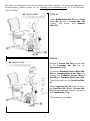
The SUNNY Health Fitness SF-RB420046 recumbent bike is a versatile piece of exercise equipment designed to provide a low-impact, comfortable workout experience for users of all fitness levels. With its sturdy construction and adjustable features, it offers a range of benefits to support your fitness journey. The recumbent design allows you to exercise in a reclined position, reducing strain on your back and joints while still effectively engaging your major muscle groups.
The SUNNY Health Fitness SF-RB420046 recumbent bike is a versatile piece of exercise equipment designed to provide a low-impact, comfortable workout experience for users of all fitness levels. With its sturdy construction and adjustable features, it offers a range of benefits to support your fitness journey. The recumbent design allows you to exercise in a reclined position, reducing strain on your back and joints while still effectively engaging your major muscle groups.


-
 1
1
-
 2
2
-
 3
3
-
 4
4
-
 5
5
-
 6
6
-
 7
7
-
 8
8
-
 9
9
-
 10
10
-
 11
11
-
 12
12
-
 13
13
-
 14
14
-
 15
15
-
 16
16
-
 17
17
-
 18
18
-
 19
19
-
 20
20


SUNNY Health Fitness SF-RB420046 User manual
- Type
- User manual
The SUNNY Health Fitness SF-RB420046 recumbent bike is a versatile piece of exercise equipment designed to provide a low-impact, comfortable workout experience for users of all fitness levels. With its sturdy construction and adjustable features, it offers a range of benefits to support your fitness journey. The recumbent design allows you to exercise in a reclined position, reducing strain on your back and joints while still effectively engaging your major muscle groups.
Ask a question and I''ll find the answer in the document
Finding information in a document is now easier with AI
Related papers
-
 SUNNY Health Fitness SF-RB4953 User manual
-
 SUNNY Health Fitness SF-RB4936 User manual
-
SUNNY Health Fitness SF-RB4850 User manual
-
 SUNNY Health Fitness SF-RB4936 User manual
-
 SUNNY Health Fitness SF-RB420046 User manual
-
 SUNNY Health Fitness SF-B223011 User manual
-
 SUNNY Health Fitness SF-RB4708 Cross Training Magnetic Recumbent Bike User manual
-
SUNNY Health Fitness SF-B1877 User manual
-
 SUNNY Health Fitness SF-B1970 User manual
-
SUNNY Health Fitness SF-B1995 User manual


Other documents
-
 Sunny Health & Fitness SF-RB4806 User guide
-
Sunny SF-E320047 User manual
-
 Sunny Health & Fitness SF-RB4631 User guide
-
 Sunny Health and Fitness SF-B220030 User manual
-
 Sunny Health & Fitness SF-B1735 User guide
-
 Sunny Health & Fitness ZEPHYR AIR BIKE User manual
-
Sunny SF-B1423 User manual
-
 Sunny Health & Fitness SF-B1423 User manual
-
-
 Sunny Health & Fitness SF-RW5856 User guide


