VEC-1680K Owner’s Manual Vacuum Tube Preamp
5
instructions. If you can't positively identify an unfamiliar item on the basis of the
information given, set it aside until all other items are checked off. You may
then be able to identify it by process of elimination. Finally, your kit will go
together more smoothly if parts are organized by type and arranged by value
ahead of time. Use this inventory as an opportunity to sort and arrange parts so
you can identify and find them quickly.
"
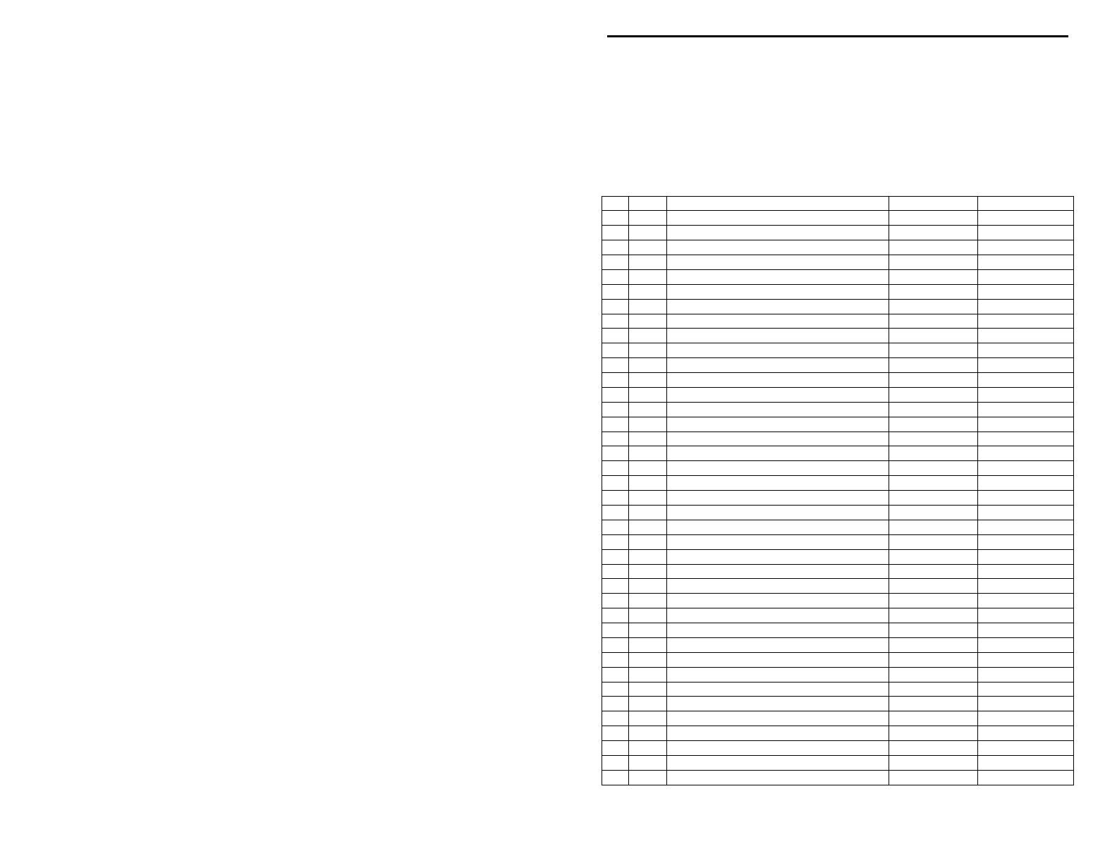
Qty Part Description Designation VEC P/N
!
2 100 ohm 2 watt resistor (brn-blk-brn) R12, R13 104-2100
!
2 3.3K ohm ½ watt resistor (org-org-red) R1, R11 101-3330
!
2 10K ohm ¼ watt resistor (brn-blk-org) R5, R7 100-4100
!
1 22K ohm ¼ watt resistor (red-red-org) R8 100-4220
!
2 390K ohm ¼ watt resistor (org-wht-yel) R3, R4 100-5390
!
2 1M ohm ¼ watt resistor (brn-blk-grn) R2, R6 100-6100
!
2 500K chassis mounted potentiometer R9, R10 153-5500-1
!
1 .01 uF disc ceramic capacitor (103) C7 200-2100
!
2 .1 uF disc ceramic capacitor (104) C10, C11 200-3100-1
!
2 .22 uF multilayer capacitor (224) C3, C9 220-3220
!
3 10 uF 350 volt electrolytic capacitor C1, C2, C6 270-5100x-6
!
3 100 uF 25 volt electrolytic capacitor C4, C5, C8 270-6100-1
!
1 1N4148 diode D6 300-4148
!
5 1N4007 diode D1-D5 300-4007
!
1 12AX7 tube V1 380-12AX7A
!
1 12.6 volt 1 amp power transformer T1 406-1114
!
1 Power switch, SPST SW1 507-1028
!
1 Relay, 2P2T RLY1 408-2042
!
3 ¼” phone jack J1, J2, J4 601-1005
!
1 2.1mm power jack J3 601-6121
!
1 Power Adapter, 12 VAC @ 1 amp 407-1072
!
1 Tube socket, 9 pin 625-12AX7A
!
2 Screw, 2-56 652-0375
!
6 Nut, 2-56 705-0256
!
6 Screw, self-tapping, type B 654S-0250B-B
!
6 Screw, 6-32 x ¼” 656-0250
!
2 Kep Nut, 6-32 705-0632-K
!
3 Nut, metric 9mm 706-7075
!
3 Flat washer 710-2550
!
2 Spacer, ¾” threaded 6-32 716C-0750
!
2 Knob 760-0033
!
1 Shielded wire, RG316 (12”) 878-0316
!
1 Orange and white twisted pair (4”) 871-2239
"
Qty Part Description Designation VEC P/N
!
2 Hook-up wire (12”) 871-24
xx
-1200
!
1 PC board, 2 sided 862-VEC1680
!
1 Chassis, punched 800-VEC1680
!
1 Chassis plate 804-VEC1680
!
4 Stick-on rubber feet 770-1162


